
Since I began uploading models to the website in 2019, I have always included an assembly guide. For simple models, one diagram is usually enough; for complex models the guide can be as detailed—or more—than the model itself. Many people have asked how I create these guides, so here’s a concise explanation of my process and lessons learned.
Background
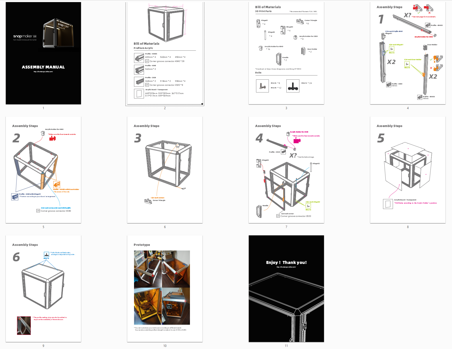
My first detailed guide was for the “Enclosure for Snapmaker 2.0” (for the Snapmaker A250). The enclosure uses aluminum profiles, acrylic panels, 3D-printed parts, and screws. I built it myself and could assemble it from memory, but I needed a way to guide others if I wanted to share the model with them. After producing a detailed guide, other users were able to reproduce the enclosure successfully. That experience started my ongoing practice of making complete assembly guides.
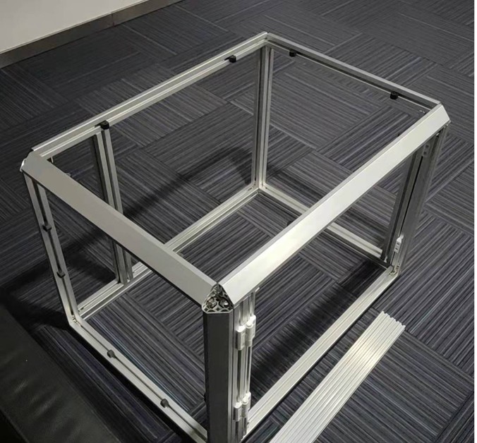
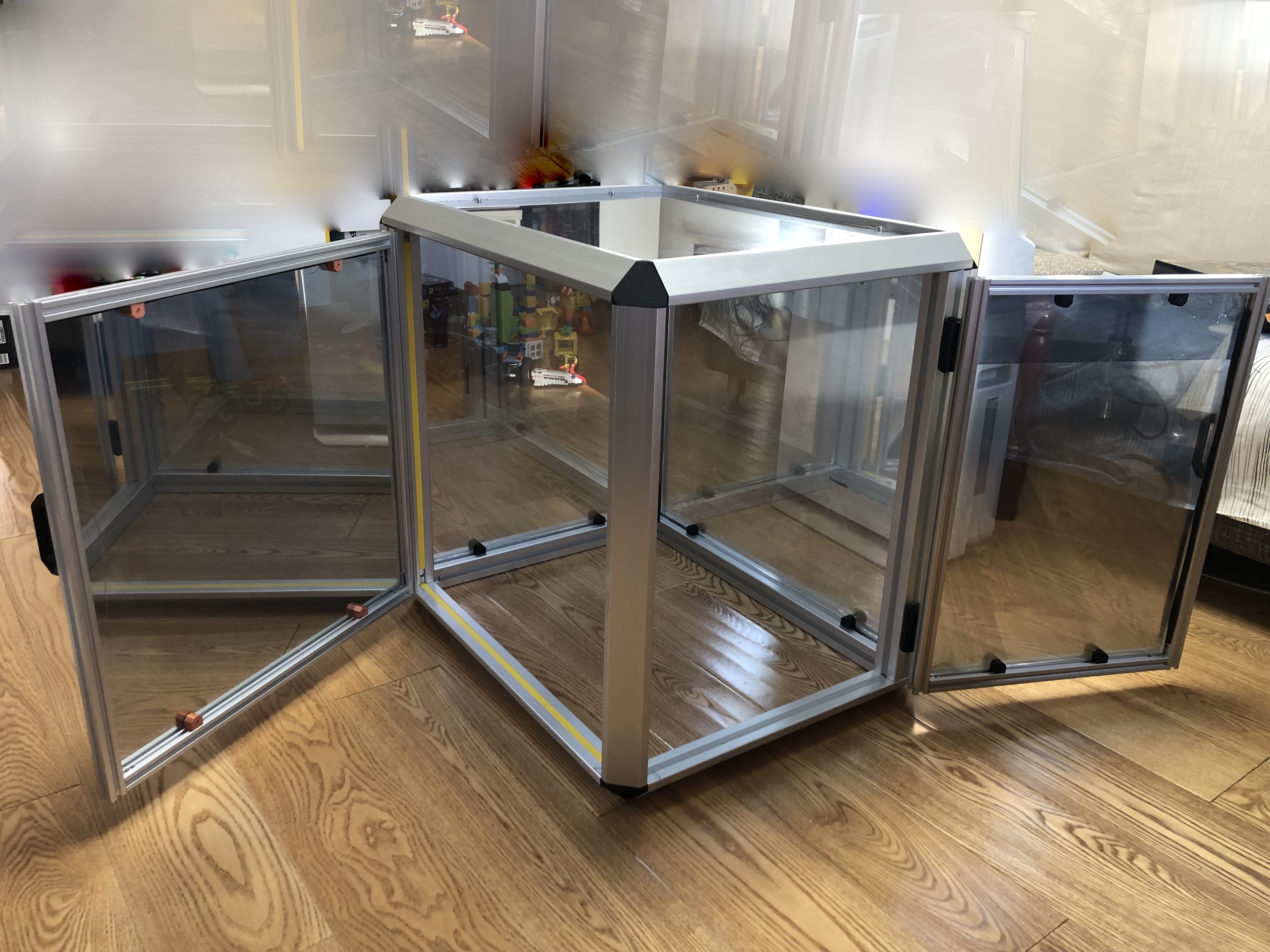
“Make” by others:
Layout and Tools
- You can use any design software (Photoshop, Illustrator, CorelDRAW, etc.).
- Because many users print guides, I recommend A4 portrait layout. (Not all my models’ assembly guides are in this type; before, I didn’t realize users would print them.)
- I divide the assembly guide into three main parts: Brief, Bill of Materials, and Diagram & Instructions. (Note: I now usually put the Brief in the model’s online “Model Information,” so the guide typically contains the last two parts.)
1. Bill of Materials (BOM)
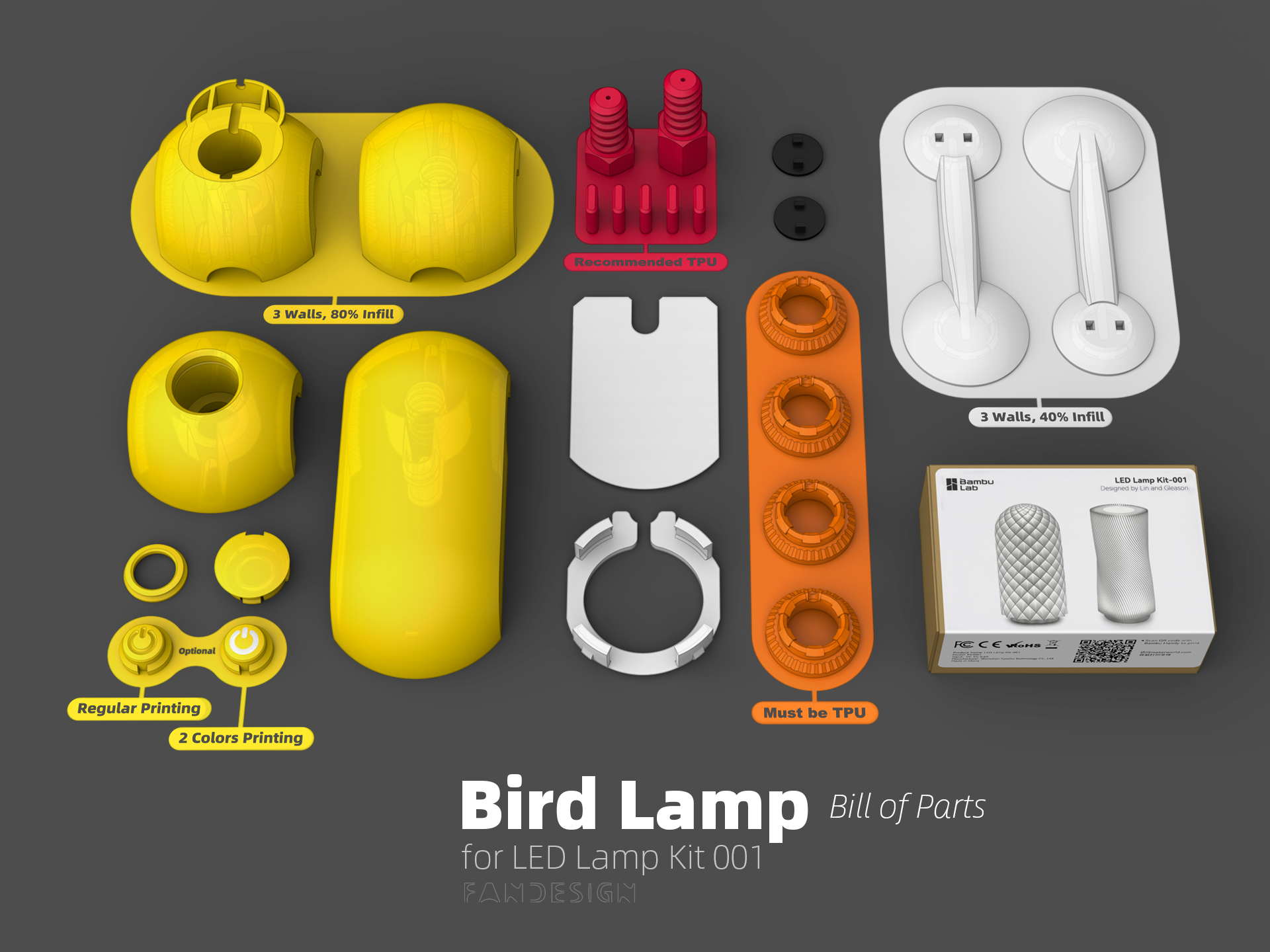
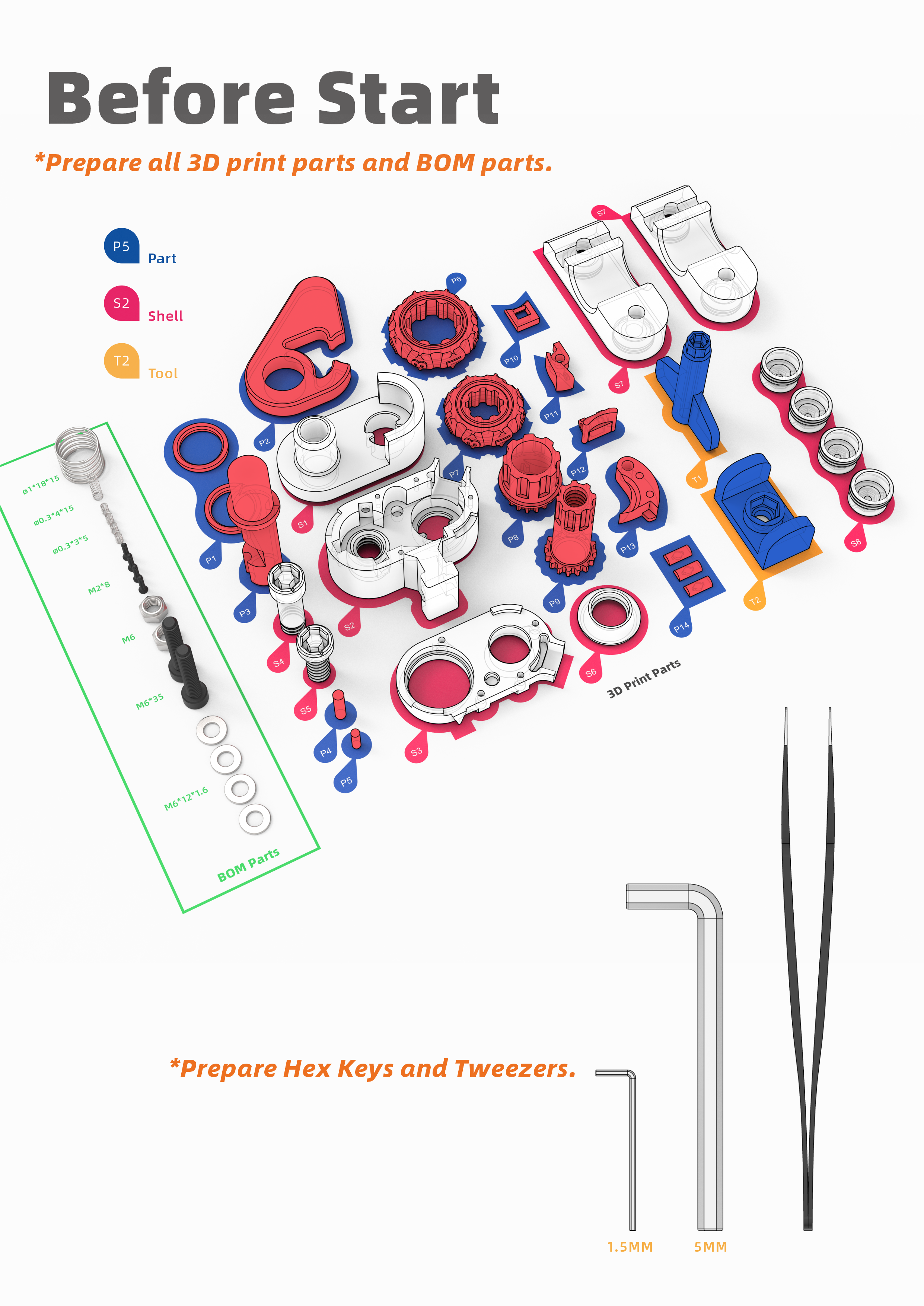
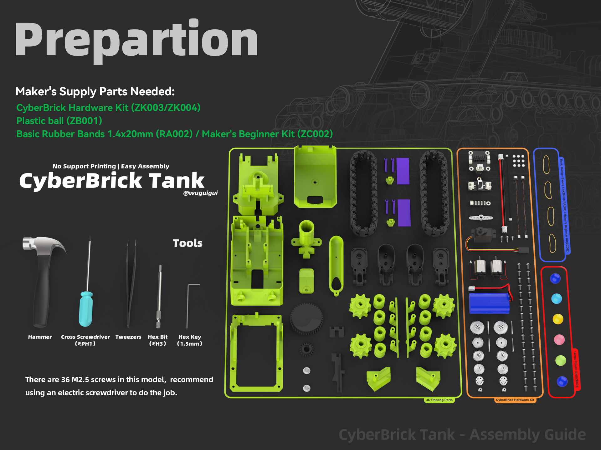
- The BOM lists every item needed: 3D-printed parts, non-printed parts, tools, and special-filament requirements.
- I prefer presenting everything in a single image so users can check at a glance—this is my “Before Start” checklist.
Numbered part labels (like plastic model kits) help identification(Cipher Helmet Lock), but add a lot of work because every step must keep labels consistent. For moderately simple models, I avoid full numbering to save time—and sometimes a little discovery is enjoyable for the builder, as the image shows below.
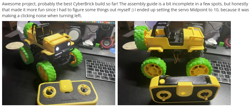
Comment on the model page of 4x4 Mini Off-Roader
These are some examples of my “Before Start”.
2. Diagram & Instructions
2.1 Diagram
- Use the same CAD software you modeled the parts in to export diagrams. I use Rhinoceros, but any CAD package will work. The advantage is you already have all parts and correct perspectives in the CAD environment.
- My preferred method in Rhinoceros: export two transparent PNGs from the same viewport—one in Rendered mode (shows realistic color and shading) and one in Pen mode (shows clear edges). Combine them in layout software and set the Pen layer transparency to 40–60% to get images that are both realistic and clear. If you're not a Rhinoceros user, there's no need to import your model files into Rhinoceros. Simply stick to the CAD software you're already using. The key point is to ensure that the diagrams you create closely resemble the real model parts and have clear edges for users to understand.
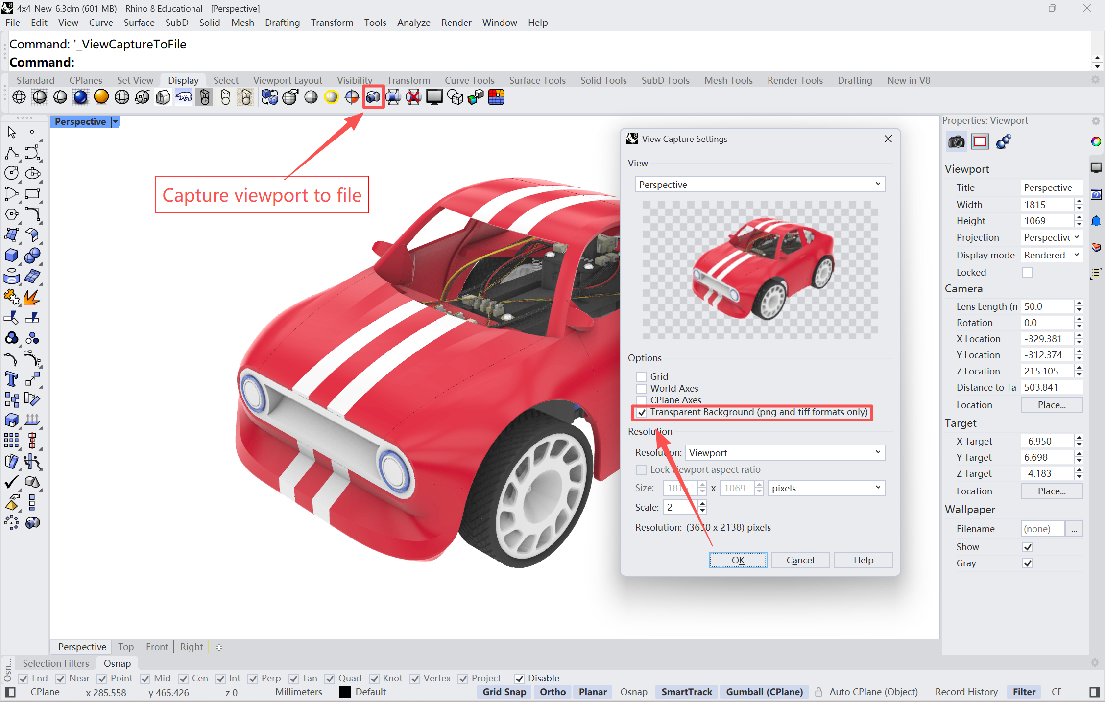
Use the “Capture viewport to file” command to save a Rendered mode image with “PNG” format in Rhinoceros 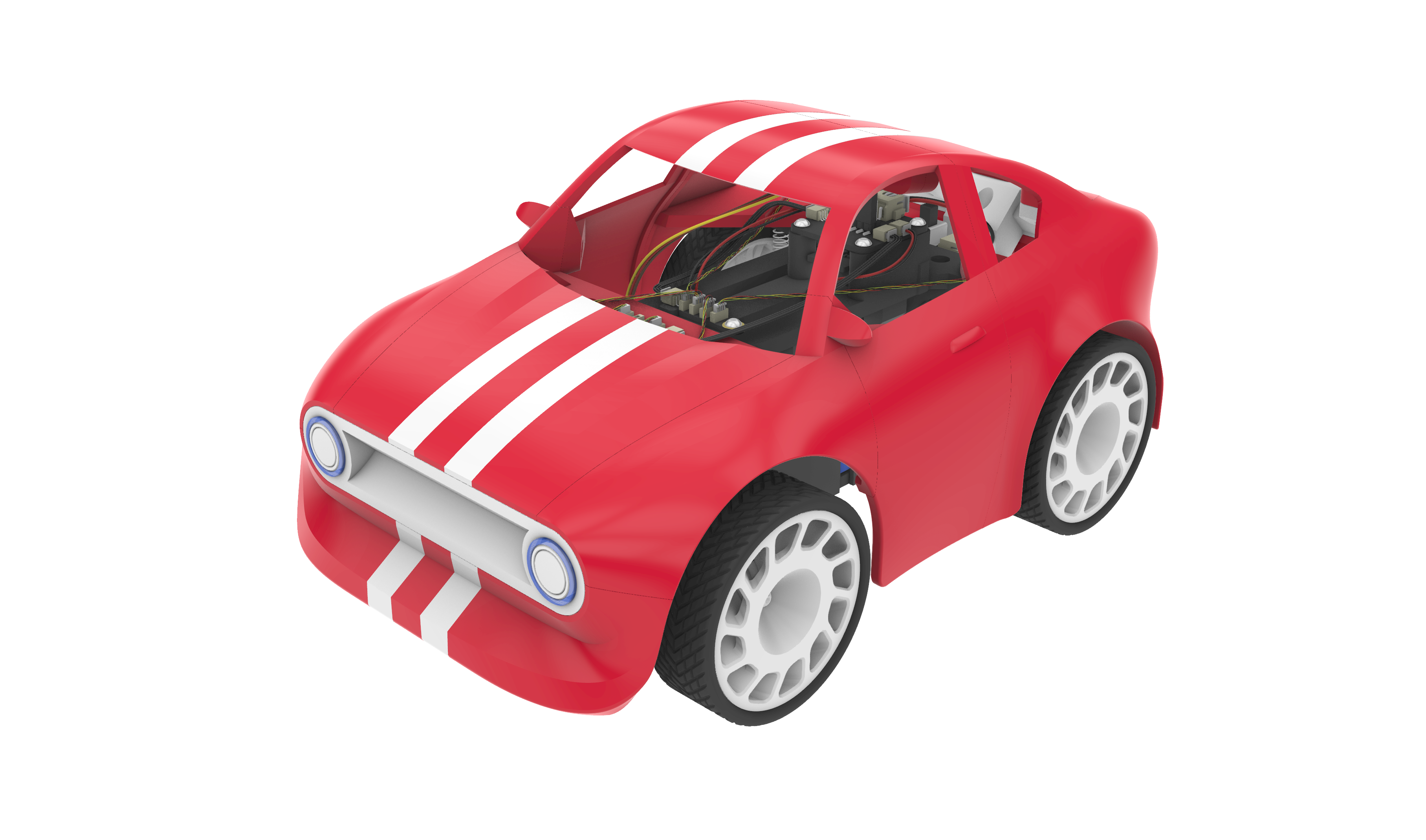
Rendered mode PNG image with transparent background 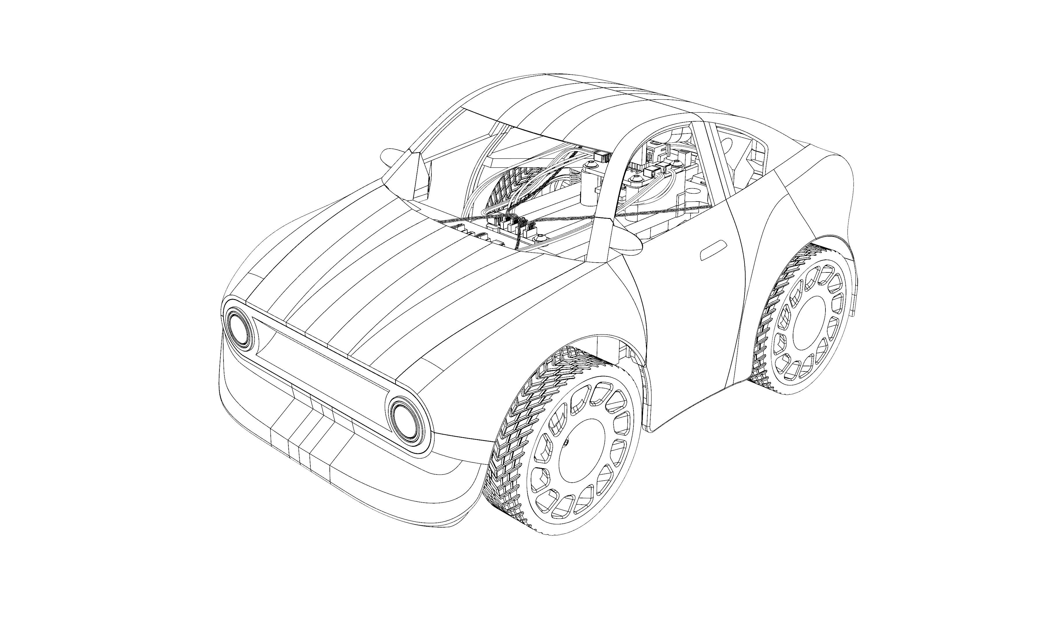
Pen mode PNG image with transparent background 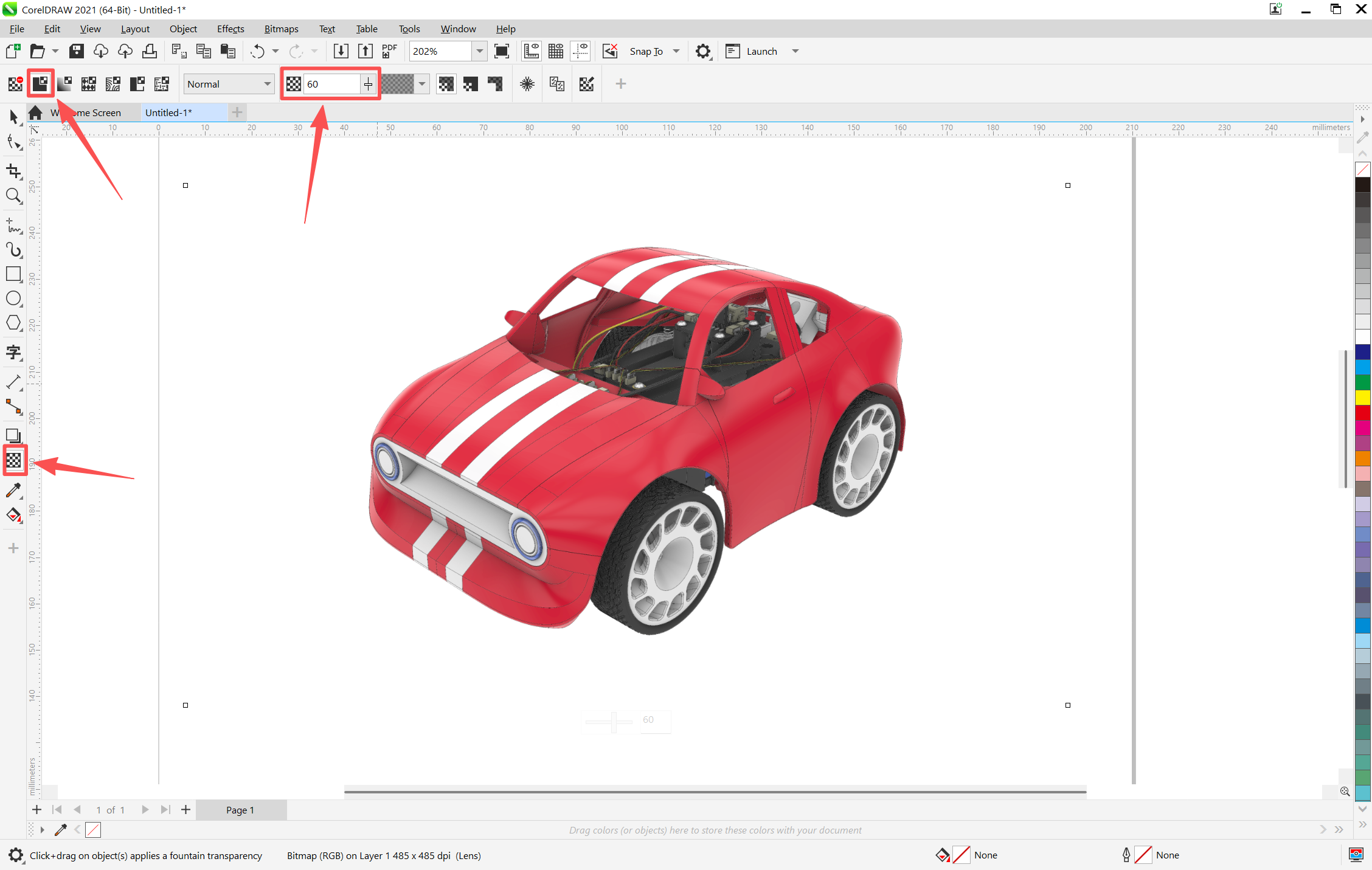
Combine 2 images in CorelDraw and set the Pen layer transparency to 40–60% - An alternative is to “Make 2-D drawing” and export vector curves (.ai/.dwg) for an IKEA-style look; vectors are editable but lack shading/shadow and require re-export if the viewpoint changes.
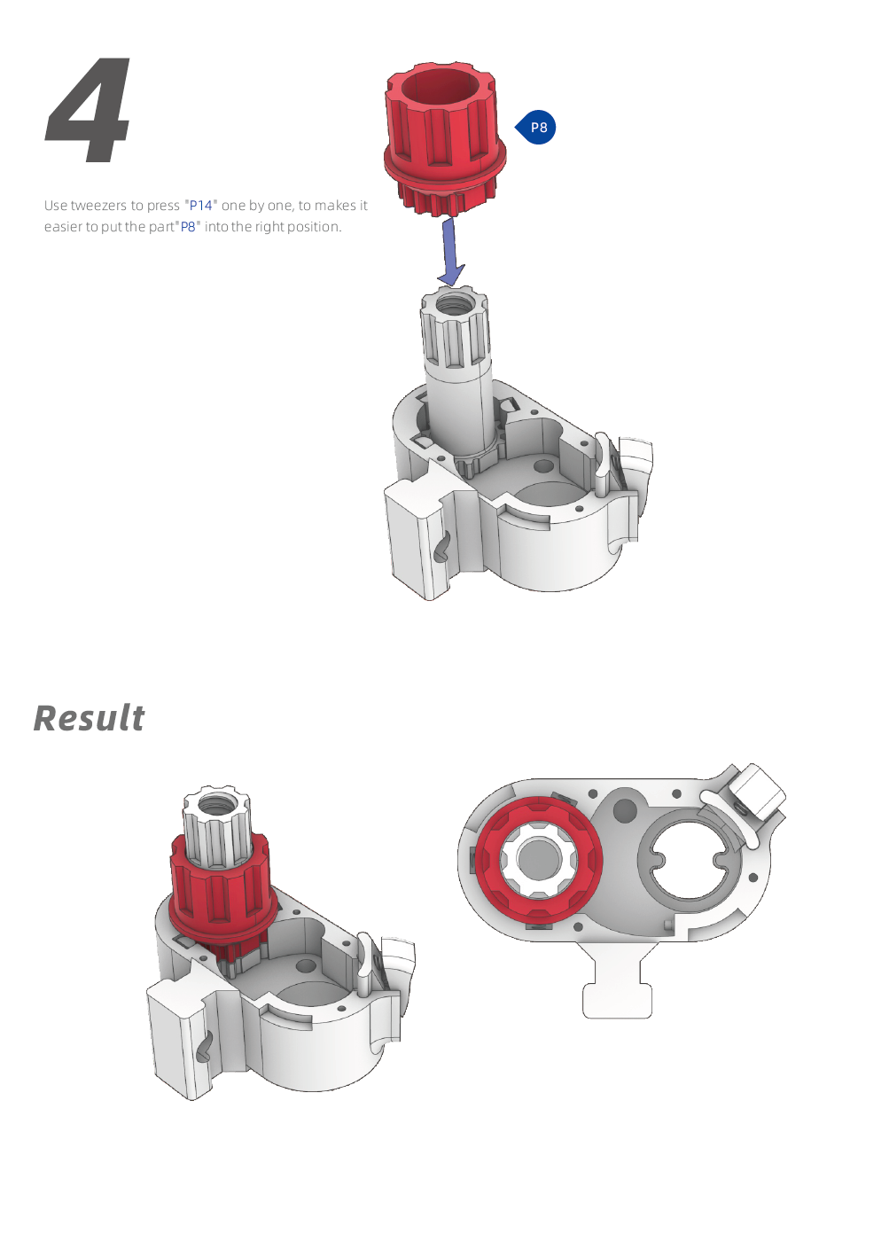
For highlighting, you can color parts differently to show assembled vs. to-be-assembled parts . As the images show below(Cipher Helmet Lock), all the parts in step 3 are in white in step4, only the to-be-assembled parts are in red. It’s a good way to highlight to-be-assembled parts. But requires a significant amount of time and effort to make diagrams.
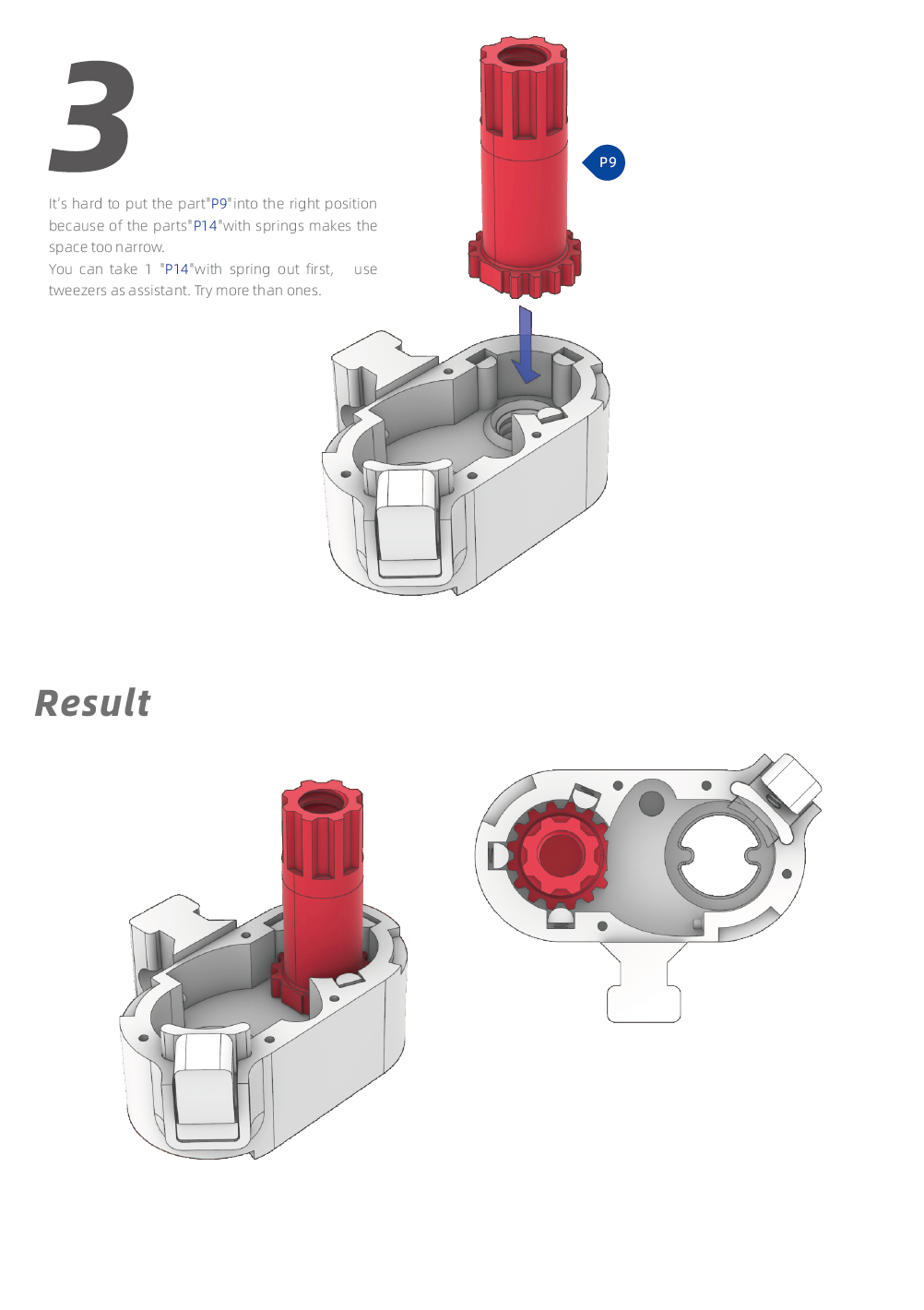
2.2 Instructions
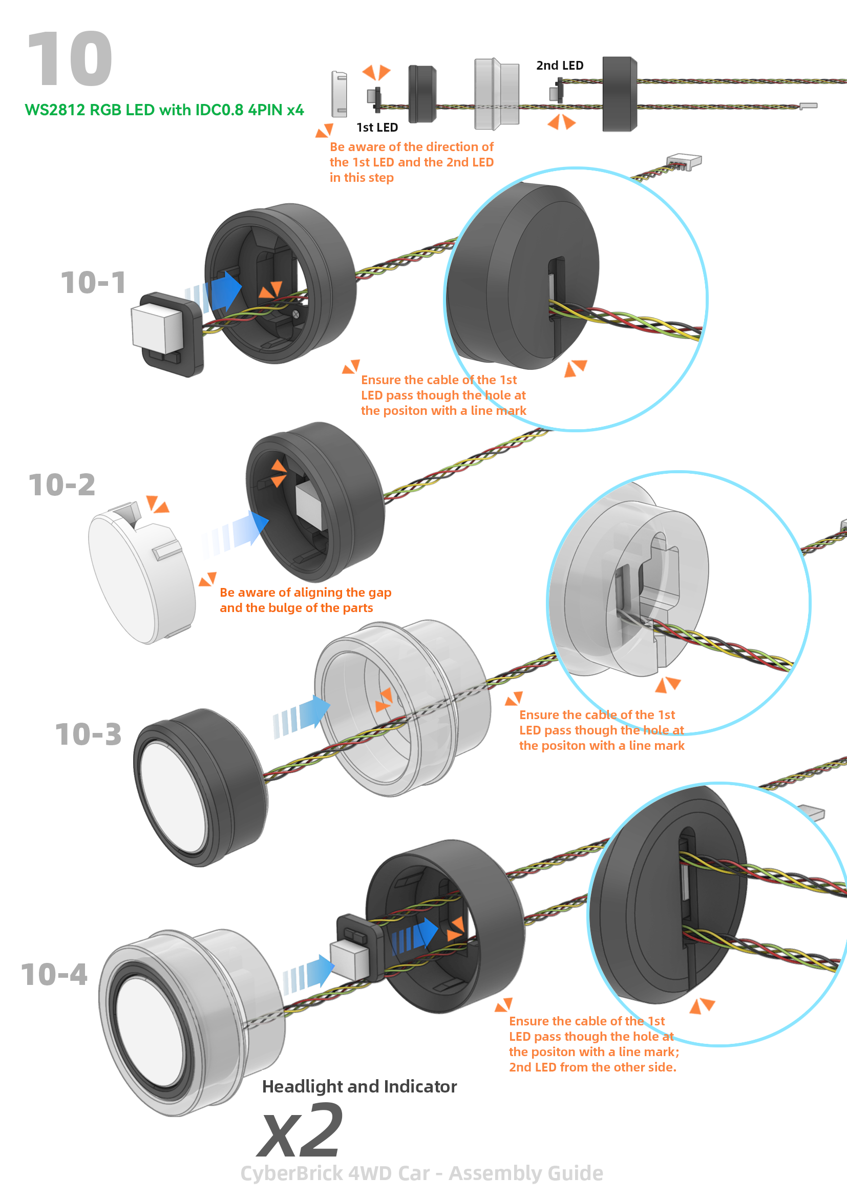
Step groups and sequences: Break complex assemblies into major steps and smaller sequences to keep the flow clear. As the image shows below(CyberBrick 4WD Car).
Arrows: I model arrows in CAD so they share the same perspective as parts—this clarifies insertion/rotation directions.
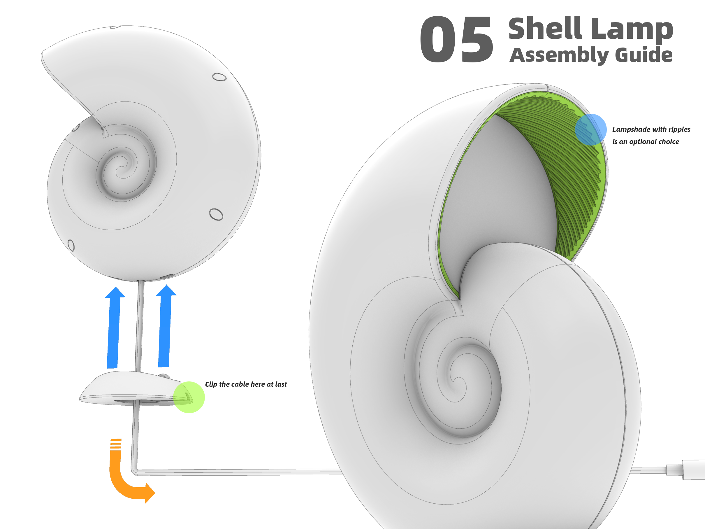
Shell Lamp V2.0 Attention marks and notes: Use bright, consistent markers (I use two orange triangles) to call out cautions or critical details.
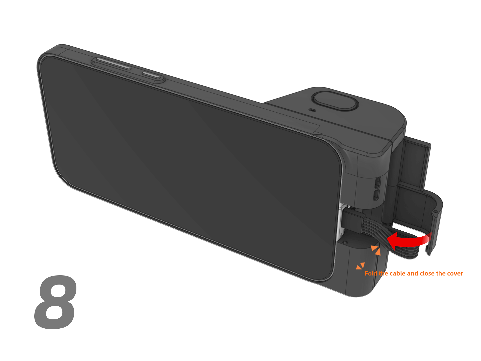
Camera with Shutter Case for Realme GT8 Pro
Practical Tips & Tradeoffs
- Numbering every part is precise but costly in time—reserve it for highly complex projects or when part interchangeability is likely.
- Combining Rendered + Pen images gives the best balance of realism and clarity for complex parts.
- Color-highlighting is effective but scales poorly without a tool to manage parts and sequences.
The purpose of any assembly guide is to help users understand the process clearly, avoid errors, and successfully complete the build. Making high-quality guides is time-consuming but essential for reproducibility. I hope someone can develop better, more user-friendly authoring tools that can simplify this work later.
One Last Thing
Please use genuine software during all stages of model creation and assembly guide production—supporting official tools encourages continued development of better, user-friendly tools, doesn’t it?
The software I use for model creation and assembly guide production:
CorelDRAW Graphics Suite 2021 for Windows
Rhinoceros 8 Educational for Windows
Thank you for supporting me always. I hope this article can provide some inspiration for your assembly guide production.


