
When installing screws into 3D-printed parts, you may have experienced cracked parts, long assembly time, and repeated testing. Now it's time to say goodbye to these issues.
In 3D printing projects, screws are a common method for connecting parts. However, if the screw holes don't match the screws, it often causes the following problems.
- When screw holes are too small, it can make it hard to screw in, cause the screwdriver to slip out of the screw head, or crack the parts. This could cause installation failure.
- When screw holes are too large, the threads formed during screwing are weak and easy to strip.
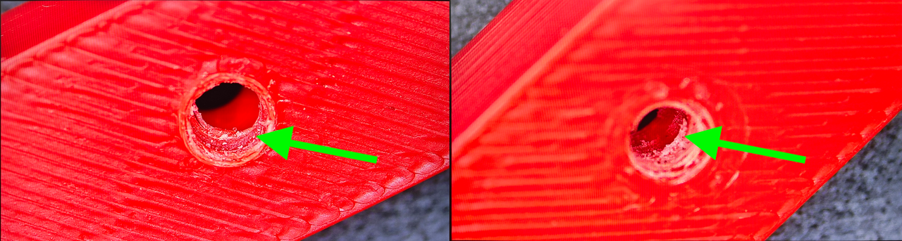
Installing many screws or deep screws takes longer and is tiring.
How to solve these problems to make the screw and the screw hole fit perfectly?
To fix this, we first need to know what affects screw hole size. Then, we will look at the design and print settings to find out how to design strong, easy-to-use screw holes. Let's start by discussing the following topics.
- Machine screws: uses and screw hole design
- Design the thread engagement length
- Self-tapping screws: advantages, uses, and screw hole design
What affects screw hole size
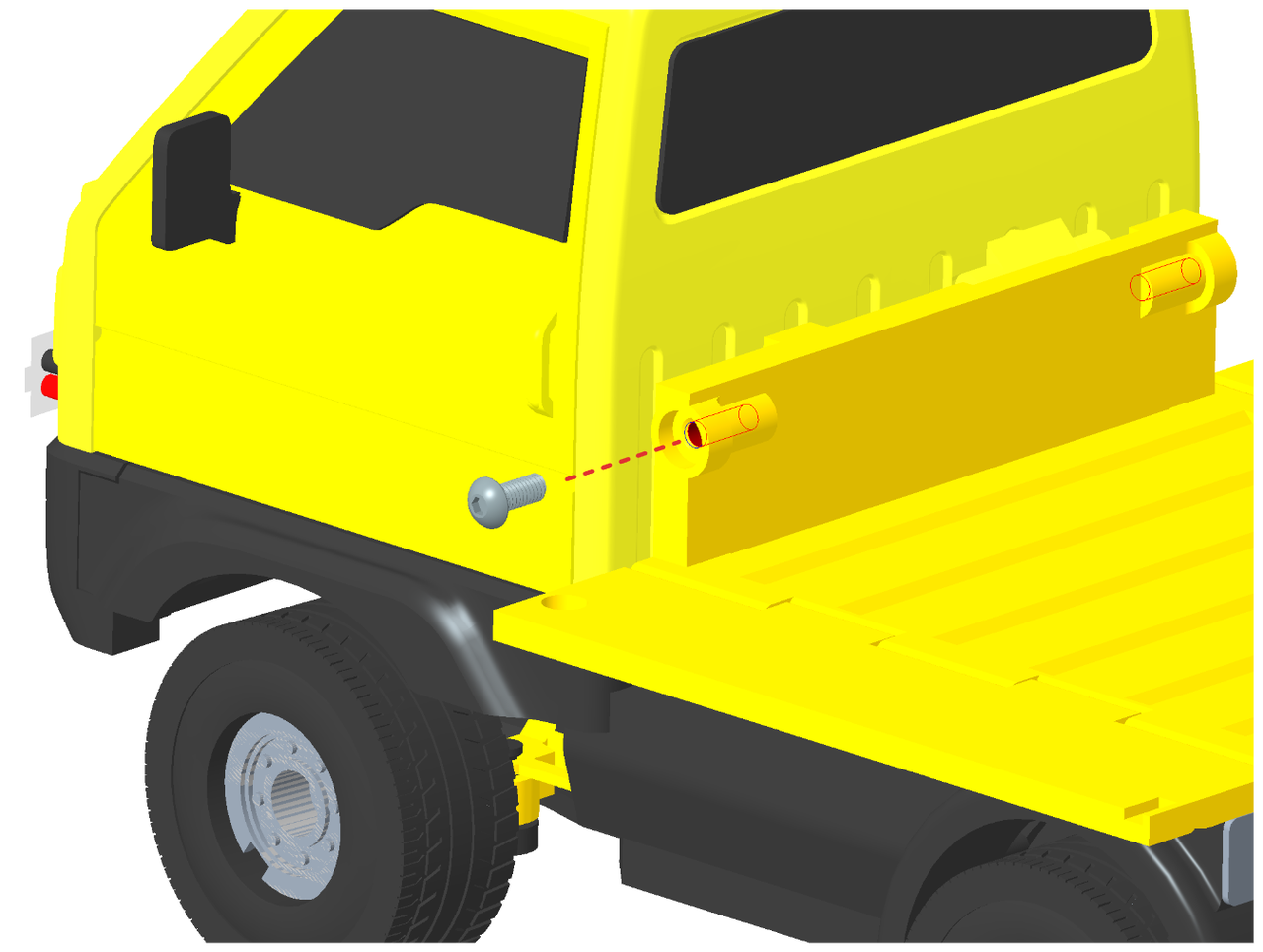
What factors affect screw hole size? How do these factors change the screw hole size?
We need to consider the screw type and size when designing screw holes. For example, consider a screw's major and minor diameters, thread pitch (thread-to-thread distance), and the material of the part being fastened.
Besides, the following factors will affect the actual size of the screw hole. So, we need to keep them in mind and adjust the hole diameter during design.
- Material shrinkage
- The direction the screw hole faces
- Mechanical properties of the filament
Usually, the screw fits properly when the hole's final diameter is a bit smaller than the pitch diameter, which is the middle size of the screw thread. When you want to try out a new filament and need to use screws, it is worth starting with this suggested design size.
Material shrinkage
Shrinkage causes the final screw hole to be smaller than the design. The type of filament and fillers can change how much material shrinks.
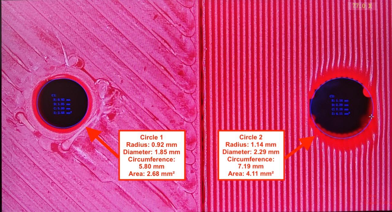
Different types of filaments shrink by different amounts. For example, the shrinkage varies between PLA and PETG. Even filaments of the same kind can shrink differently depending on their color. That is because the fillers used to create the color affect shrinkage. For example, black PLA Basic filament's shrinkage differs a lot from that of other PLA filaments (the image below).
If the material doesn't cool completely, the liquid rope coil effect causes the holes to shrink further. With smaller holes, a decrease in diameter is more noticeable.
The direction the screw hole faces
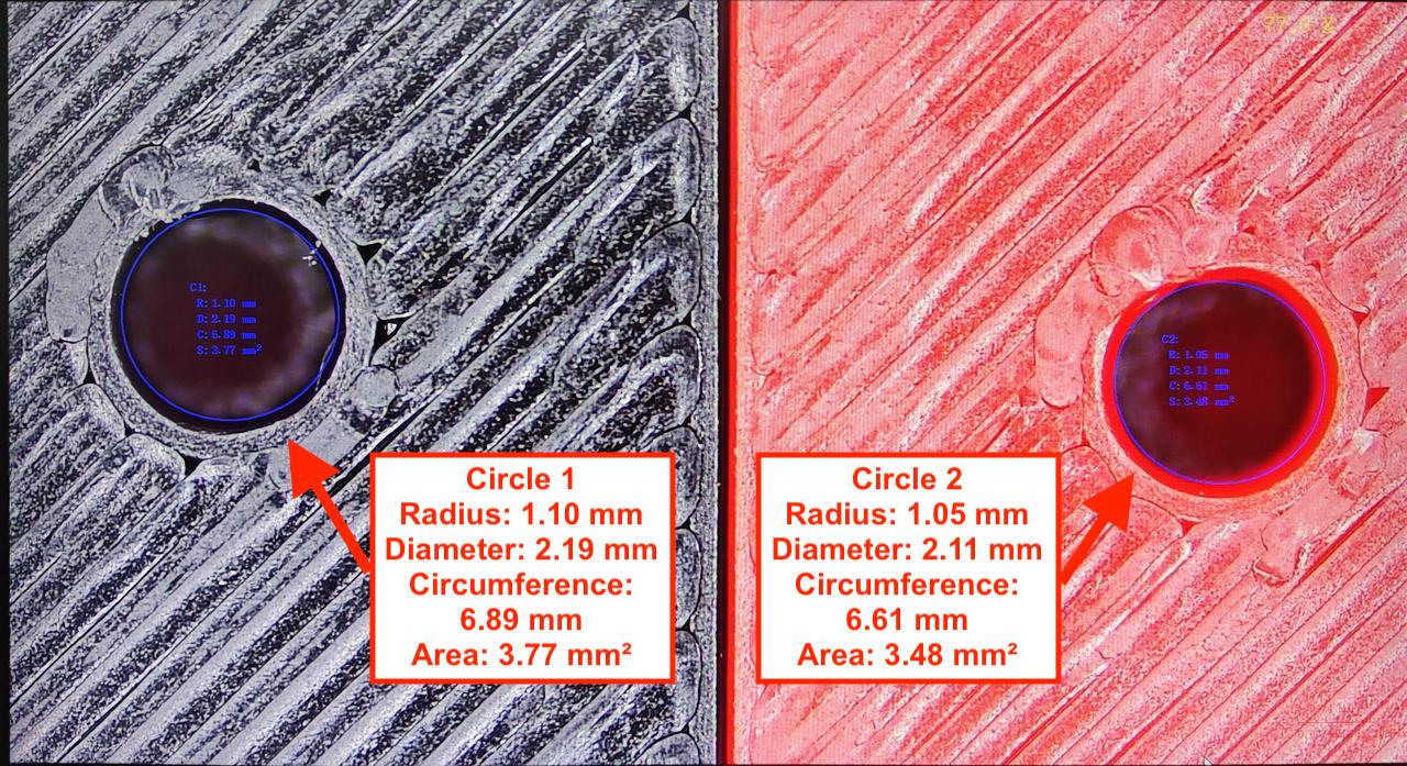
Screw holes are sorted by the direction they face, either horizontal (left image) or vertical (right image). When the screw hole opening surface is parallel to the print bed, we call it a horizontal screw hole. When the screw hole opening surface is at a right angle to the print bed, we call it a vertical screw hole.
Material cooling and the seam affect the size of horizontal screw holes. The smaller the horizontal hole, the greater the liquid rope coil effect, and the nozzle drags the unsolidified filament. This leads to more shrinkage.
FDM printing is built layer by layer, so the vertical screw hole walls are not continuous between layers. Thus, horizontally, shrinkage affects the hole diameter less, making it closer to the design than in horizontal holes. Vertically, the screw hole is a bit smaller. This is caused by overhang, layer stepping, or when the printer needs to cross a gap, known as bridging.
Mechanical properties of the filament
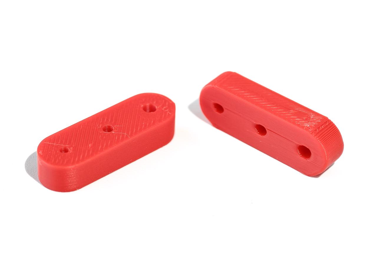
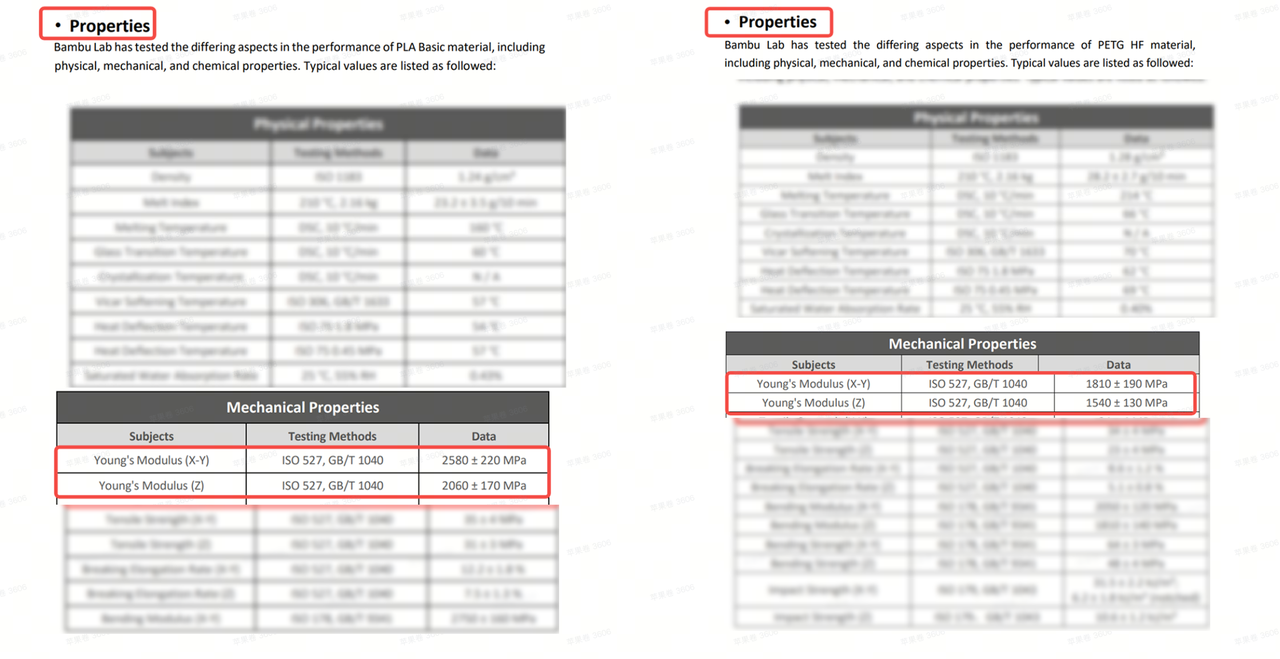
Different filaments have different hardness. PLA is relatively hard. This makes it easier to form threads when installing screws. PETG is softer and can be easily damaged when installing screws. So, when designing screw holes, we need to use different hole diameters for PLA and PETG. Usually, a slightly smaller hole diameter is suitable for soft materials to form threads. When working with hard filaments, be mindful not to overpress and crack the material when you screw it in.
The left image shows PLA Basic's mechanical properties. The right image shows PETG HF's. All Bambu filament specs include detailed technical data sheets. You can get the mechanical properties data from technical data sheets. Please take a look at Young's Modulus values to find out the material's stiffness. The larger the value, the stiffer the material is.
Once we know what affects screw hole size, how should we design it for machine screws and self-tapping screws? And how should we design the thread engagement length? The thread engagement length is the part of the thread that grips the material and carries the load. Let's keep going.
Machine screws: uses and screw hole design
Machine screws are not designed for plastic parts. However, machine screws are widely used in printed parts. Machine screws are widely used and easy to buy.
We suggest using machine screws in the following cases:
- When you don't need to take the screw out often, or when you don't need a high built-in tension to clamp parts together.
- When you have already used machine screw nuts elsewhere in the part. Using machine screws helps reduce the number of screw types needed.
Hole diameter for machine screws
For M2 - M4 machine screws, we suggest designing the screw holes with the filament type in mind. See the table below for the suggested sizes. The sizes below are suitable for the Bambu X1, P1, and A1 series.
Filament: PLA
| Screw type | M2 | M2.5 | M3 | M4 |
|---|---|---|---|---|
| Pitch diameter of coarse threads (mm) | 1.740 | 2.208 | 2.675 | 3.545 |
| Diameter of horizontal screw holes (mm) | 2.10 | 2.50 | 2.90 | 3.75 |
| Diameter of vertical screw holes (mm) | 1.84 | 2.30 | 2.72 | 3.55 |
Filament: PETG HF
| Screw type | M2 | M2.5 | M3 | M4 |
|---|---|---|---|---|
| Pitch diameter of coarse threads (mm) | 1.740 | 2.208 | 2.675 | 3.545 |
| Diameter of horizontal screw holes (mm) | 1.95 | 2.45 | 2.90 | 3.75 |
| Diameter of vertical screw holes (mm) | 1.70 | 2.15 | 2.60 | 3.40 |
Filament: PETG Basic
| Screw type | M2 | M2.5 | M3 | M4 |
|---|---|---|---|---|
| Pitch diameter of coarse threads (mm) | 1.740 | 2.208 | 2.675 | 3.545 |
| Diameter of horizontal screw holes (mm) | 2.10 | 2.50 | 2.90 | 3.75 |
| Diameter of vertical screw holes (mm) | 1.74 | 2.20 | 2.72 | 3.55 |
Tightening screws requires a certain amount of preload. It keeps the screw firmly attached to the part, preventing it from coming loose. We suggest using the tightening torque from the table below to prevent damage to the screw threads. This way also improves both fastening and installation comfort.
Please do not tighten the screw by hand too hard, as it could damage the plastic parts. When using an electric screwdriver, you can just set the torque to a suitable level.
| Screw type | M2 | M2.5 | M3 | M4 |
|---|---|---|---|---|
| Thread engagement length (mm) | 4.0 | 5.0 | 5.0 | 5.0 |
| Torque (N*m) | 0.13 | 0.20 | 0.25 | 0.40 |
Fix the impact of overhangs on vertical holes
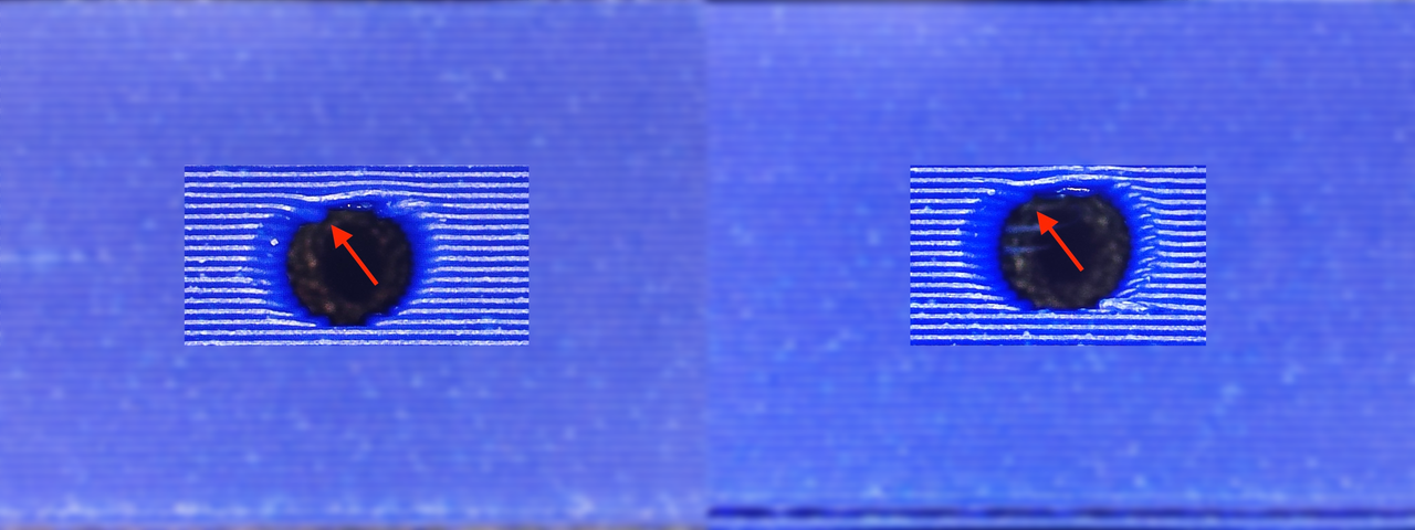
Please be aware that the print nozzle moves very fast. Its inertia can cause slight curves at the edges of the vertical holes. These slight curves look like small protrusions. The overhang at the top of the hole reduces its size. This makes it hard to start screwing a machine screw into vertical holes.
To avoid this issue, at the top edge of the vertical screw hole, design an angle of 20° to 30° (the image below). Trim the sagging part with this angle.
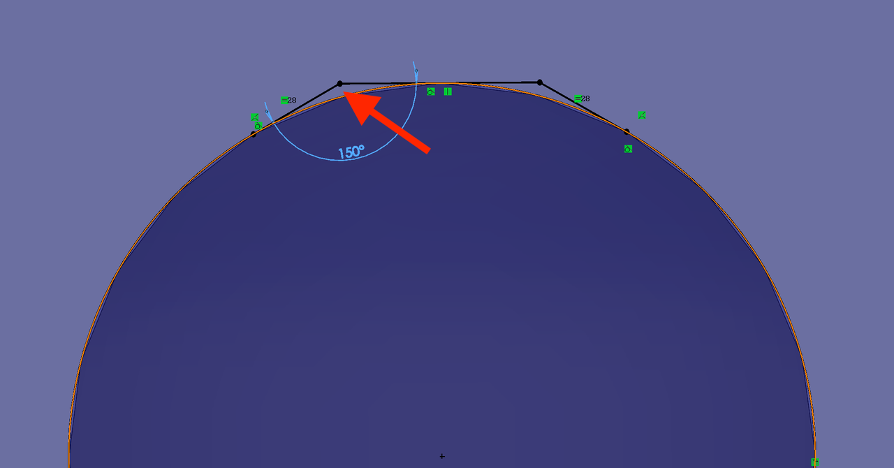
This reduces sagging at the top edge of the hole and lowers the chance of hole diameter shrinkage (the right image below).
Design the thread engagement length
Thread engagement length affects how easily and quickly screws are installed. The thread engagement length is the part of the thread that grips the material and carries the load.
How should we design this length for strength and make installation easier and better? Let's go through the following aspects together.
- Match thread engagement length for different part designs
- Design clearance
- Design lead-in chamfer
Match thread engagement length for different part designs
We need to design the thread engagement length to fit the following situations.
- The main structures that need to be tightly connected
- Connections that do not hold weight
- Parts that do not need to connect tightly
The main structures that need to be tightly connected
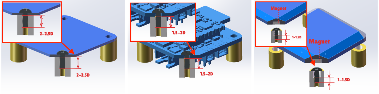
When the main structures need to be tightly connected during assembly, we suggest setting the thread engagement length to 2 to 2.5 times the major diameter (left image). For instance, the thread engagement length for an M3 screw (major diameter 3 mm) shall be set to 7.5 mm. This length strikes a good balance between how strongly the parts connect and the tightening torque.
When installing many screws with an electric screwdriver, we suggest setting the thread engagement length to 2.5 times the major diameter. This keeps threads safe from being damaged.
Connections that do not hold weight
For connections that do not hold weight, we suggest setting the thread engagement length to 1.5 to 2 times the major diameter (middle image). For instance, decorative or light internal parts that do not need to be gripped or hit. With this length setting, you can tightly fix the CyberBrick functional shields to the model.
Parts that do not need to connect tightly
For parts that do not need a tight connection, we suggest setting the thread engagement length to 1 to 1.5 times the major diameter (right image). This setting helps fix the parts tightly. For instance, screws are used together with magnets to keep the cover closed.
Please be aware that short thread engagement may cause threads to break easily. For BT2 and M2 screws, we suggest setting the engagement length to at least 4 mm. For BT2.5 and M2.5 screws, set the engagement length to at least 3 mm.
Design clearance
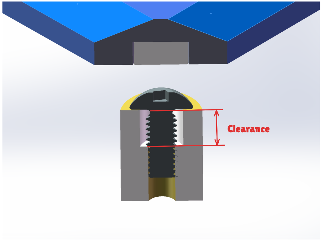
Due to screw length and space limits, the thread engagement lengths for horizontal and vertical holes can sometimes be longer than necessary.
To make installation easier, we can design a clearance at the top part of the screw hole (the image below). Set the clearance larger than the screw diameter. This reduces the number of turns to tighten a screw and the thread engagement length, making the installation process smoother.
Design lead-in chamfer
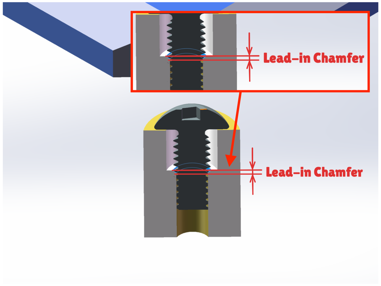
When tightening a screw, it may shift from its planned spot. This causes unstable fastening or damage to the part. So, we suggest designing a lead-in chamfer (the image below), a sloped edge to guide the screw in straight. To prevent the screw from tilting, we suggest adding a 45° chamfer at the top of the screw hole. Set the chamfer depth a bit more than half the difference between the screw's major diameter and the actual hole diameter. For instance, when designing a screw hole for an M2.5 machine screw (diameter 2.2 mm), set the chamfer depth to 0.4 mm.
Please be aware that the overlap between the lead-in chamfer and the threads is minimal. Therefore, the chamfered depth shall not be counted toward the thread engagement length. During design, we need to reserve enough depth.
Self-tapping screws: advantages, uses, and screw hole design
Compared to machine screws, these well-selected self-tapping screws are suitable for 3D-printed objects. Now, let us have a look at the features of self-tapping screws, their advantages, and the design methods.
Features of self-tapping screws
Compared to machine screws, self-tapping screws have a larger thread pitch and deeper thread roots. In the image below, the left is a machine screw, and the right is a self-tapping screw. These features help them cut into materials more easily. They also reduce the needed tightening torque and make installation easier. It also makes them more compatible with screw holes of different sizes.
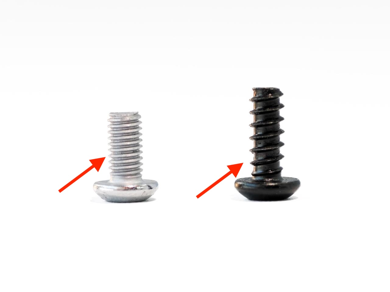
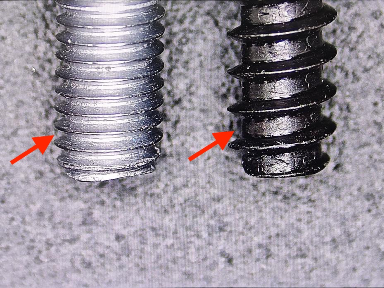
Machine screws have shallow threads. Therefore, we need more threads to ensure a strong connection. Machine screws and self-tapping screws share the same thread engagement length. But machine screws usually have about half the thread and thread pitch of self-tapping screws. Thus, it requires more turns to tighten machine screws. This makes them slower to install. (Left: a self-tapping screw; right: a machine screw.)
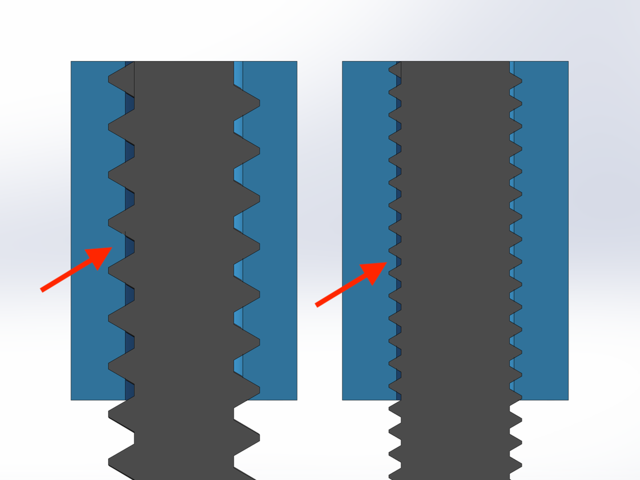
Self-tapping screws are less likely to cause cracking in materials. This helps them stay securely fastened, even after being removed or reinstalled on the original threads. Thus, compared to machine screws, self-tapping screws are a good choice when you need to take the screw out and reinstall it once in a while.
In short, when directly screwed into printed parts, self-tapping screws offer these benefits:
- Supports a wide range of filament types.
- Requires a lower torque to tighten.
- Stronger fastening.
- Ideal for limited removal or reuse.
- Fit vertical screw holes
Hole diameter for self-tapping screws
Similar to machine screws, we suggest keeping the hole diameter equal to the pitch diameter. But we need to note that BT3 screws have deeper thread roots, with a pitch diameter up to 2.38 mm.
In the default print setting, screw holes usually have two wall layers. If the screw thread cuts into the wall too deeply, the high pressure can cause the wall to break (the image below). This causes poor fastening, leaving the broken screw stuck inside the part or even cracking the part. Thus, when using large self-tapping screws, we suggest increasing the hole diameter slightly and adding extra wall layers. This helps ensure a stronger and more secure installation.
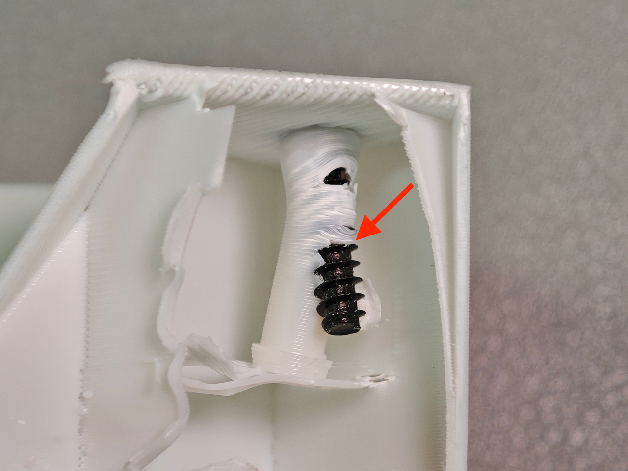
The table below suggests the screw hole diameters. You can use it to set the hole diameters and the appropriate number of wall layers.
Filament: PLA Basic
| Screw type | BT2 | BT2.5 | BT3 |
|---|---|---|---|
| Pitch diameter (mm) | 1.62 | 2.01 | 2.38 |
| Number of walls for horizontal screw holes | 2.0 | 2.0 | 3.0 |
| Diameter of horizontal screw holes (mm) | 2.00 | 2.35 | 3.00 |
| Diameter of vertical screw holes (mm) | 1.80 | 2.20 | 2.55 |
Filament: PETG HF
| Screw type | BT2 | BT2.5 | BT3 |
|---|---|---|---|
| Pitch diameter (mm) | 1.62 | 2.01 | 2.38 |
| Number of walls | 2 | 2 | 3 |
| Diameter of horizontal screw holes (mm) | 1.95 | 2.35 | 2.80 |
| Diameter of vertical screw holes (mm) | 1.60 | 2.00 | 2.40 |
Filament: PETG Basic
| Screw type | BT2 | BT2.5 | BT3 |
|---|---|---|---|
| Pitch diameter (mm) | 1.62 | 2.01 | 2.38 |
| Number of walls | 2 | 2 | 3 |
| Diameter of horizontal screw holes (mm) | 2.00 | 2.35 | 2.95 |
| Diameter of vertical screw holes (mm) | 1.65 | 2.05 | 2.40 |
For self-tapping screws, we suggest applying the tightening torque listed in the table below. It helps prevent damage to the screw threads. This way also improves both fastening and installation comfort.
Please do not tighten the screw by hand too hard, as this could damage the plastic parts.
When using an electric screwdriver, you can just set the torque to a suitable level.
| Screw type | BT2 | BT2.5 | BT3 |
|---|---|---|---|
| Thread engagement length (mm) | 4.0 | 5.0 | 6.0 |
| Torque (N*m) | 0.15 | 0.20 | 0.30 |
Adding more wall layers increases print time and filament usage. To save material, we can use the Modifier feature in the slicer software. This allows you to modify the number of wall layers only at the bottom of the screw hole. Let's have a look at how to adjust the number of wall layers together.
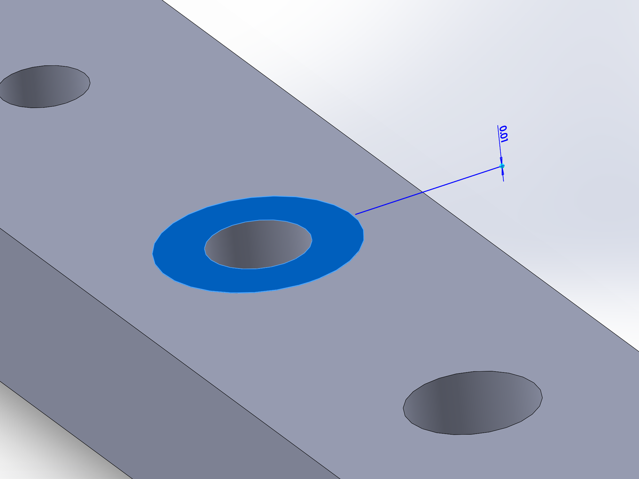
When designing your CAD model, draw a circle on the surface around the screw hole and extrude it by 0.01mm. This creates a raised circular area that helps position the modifier.
Import your model into Bambu Studio, select the part, and right-click to open the dropdown menu. Then click Add Modifier > Cylinder, then click OK in the Add Modifier pop-up.
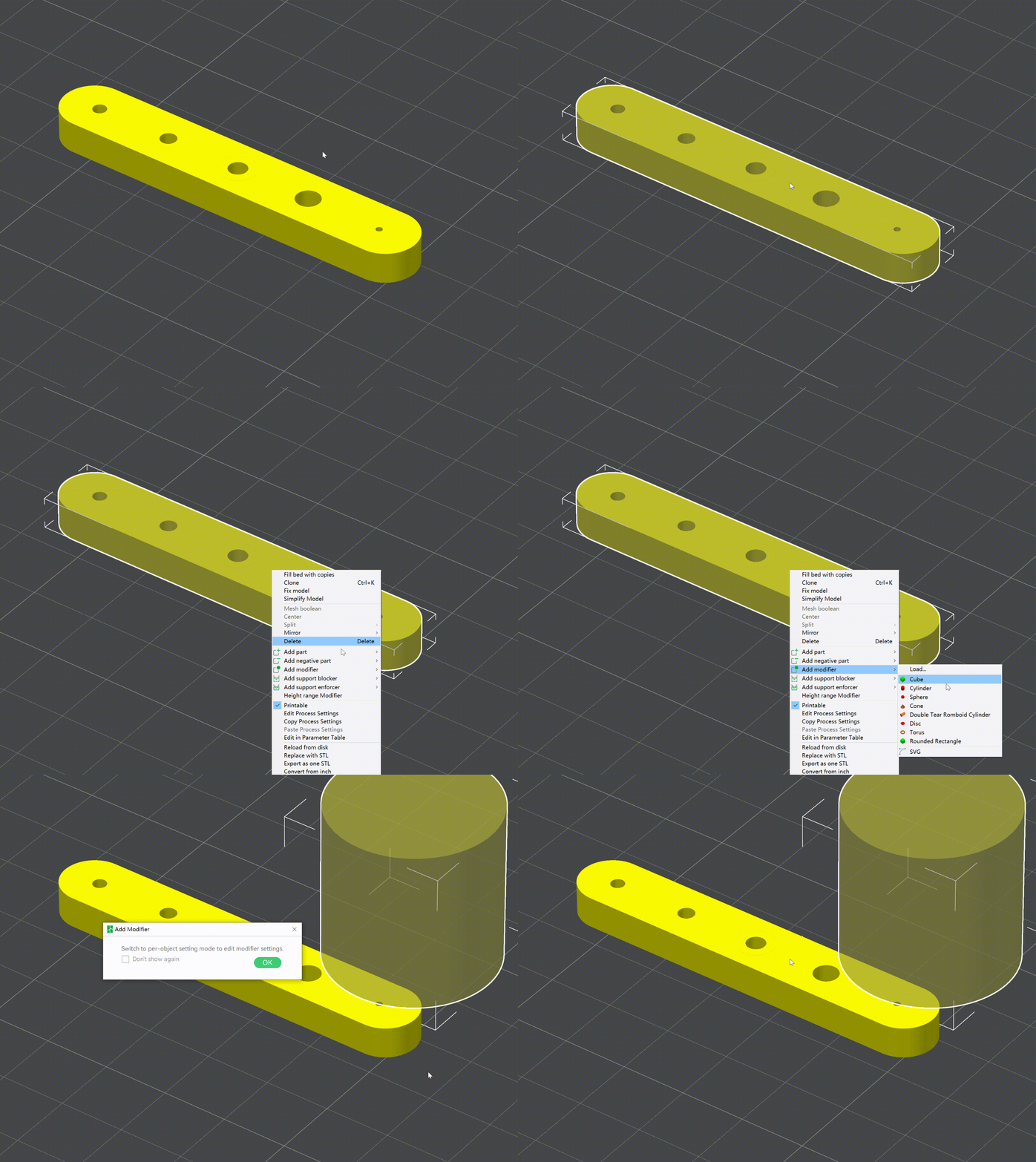
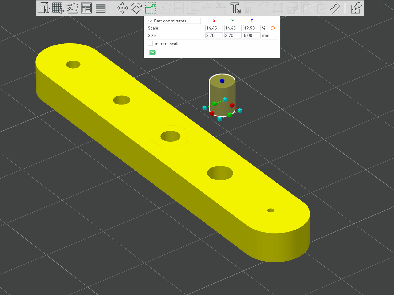
Set the modifier diameter to 0.8 mm larger than the screw hole diameter. The increased portion, i.e., 0.8 mm, equals the filament diameter x additional wall layers + 1. And make the modifier depth equal to the screw hole depth.
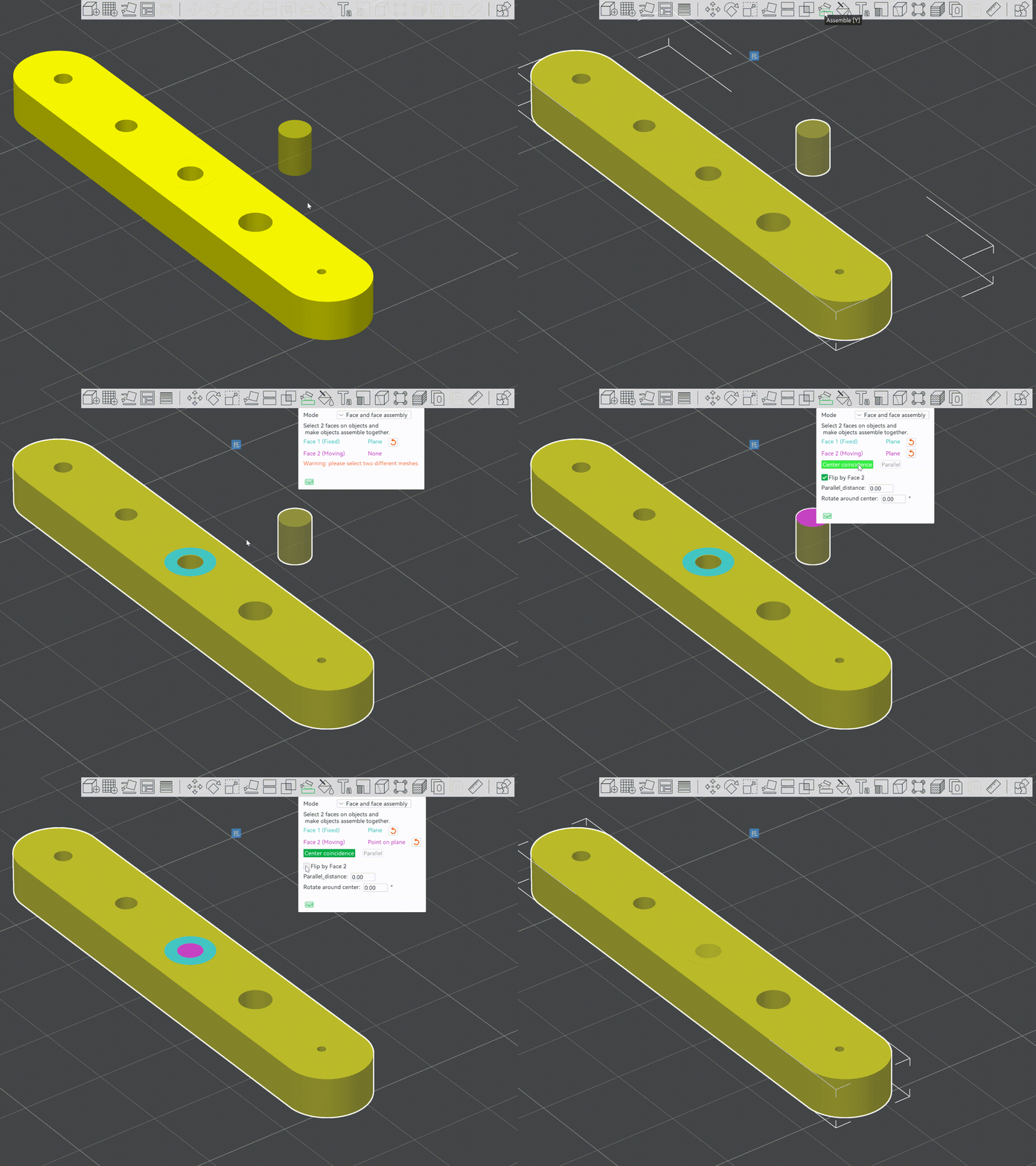
Select the part, then click the Assemble feature in the menu bar. Select the top surface of the raised circular area at the top of the screw hole. Then choose the top surface of the cylinder modifier. Click Center Coincidence, then uncheck Flip by Face 2 to embed the modifier into the screw hole.
Select the modifier, then set the Wall Loops to 3.
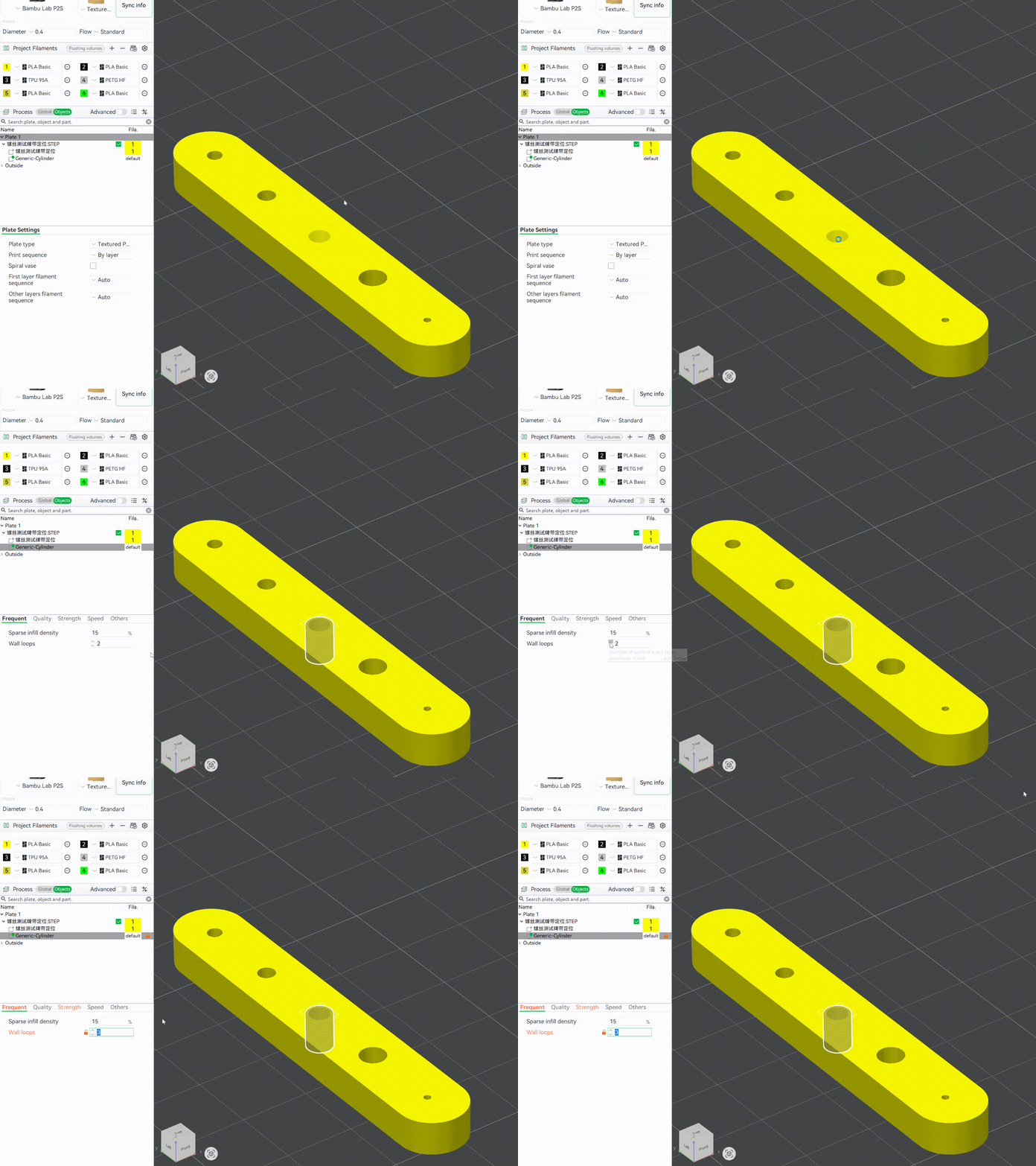
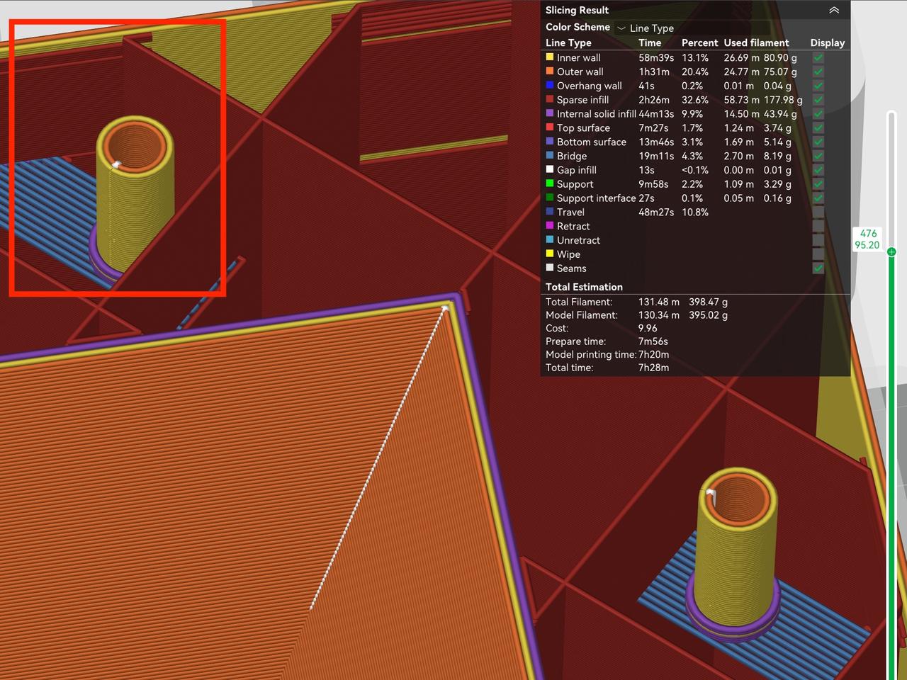
Go to Preview. You will see that the wall layer number is now 3 (the image below). All other settings stay the same.
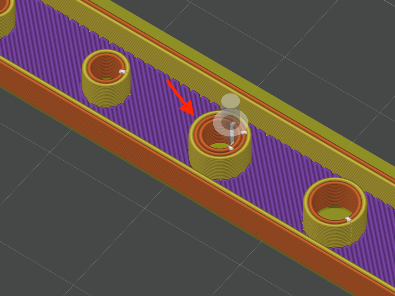
When the infill density is low, screw hole walls may not connect to the infills (the image below), and the interlayer connection area remains small. This makes some parts locally fragile.
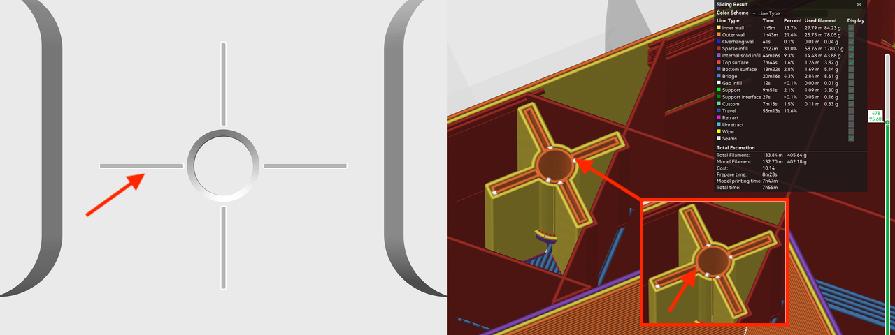
To make screw hole walls stronger, in addition to adding wall layers, we suggest designing radial slots that bridge to the hole.
In the space between the internal walls, draw thin radial slots around standalone screw holes (left image). To form a continuous hole wall, set the spacing between the radial slots and the hole wall to 1.5 to 2 times the filament width. Set the slot width to 0.2 mm, its length equal to the screw hole diameter, and its depth matching the screw hole depth. In the slicer software, this generates thin connecting walls (right image), boosting the hole's strength.
The thread engagement length for self-tapping screws
Self‑tapping screws and machine screws share the same idea about thread engagement length. Therefore, the design principles on thread engagement length described above apply to both machine screws and self-tapping screws. Check the section above for design principles on thread engagement length.
In this guide, we explored what affects screw hole size, the application of machine and self-tapping screws, the design method and recommended sizes for screw holes for both types, and the advantages of using self-tapping screws. We also covered methods for designing thread engagement length to ensure strength and efficient installation. , methods for designing
We hope these ideas make your design and installation smoother and help you avoid screw-related troubles.
Recommended reading
[1] Joseph Pinchback, "Anatomy of a Screw: Parts, Materials & More - Wilson-Garner,“ Wilson-Garner, 2023
[2] Liquid rope coil effect, ''Liquid rope coil effect'', Wikipedia, 2025
These articles might help you as well — take a look!
Ways to Fix Filament Sagging in Supportless Holes
Lithium Battery Case Design: You got this!
If this guide sparked ideas or felt familiar, share your thoughts in the comments — let’s chat! Like and save if it helped.


