On/Off switch for printer


Print Profile(1)
Bill of Materials

Description
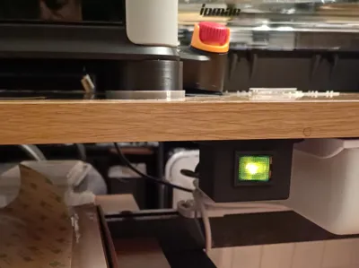
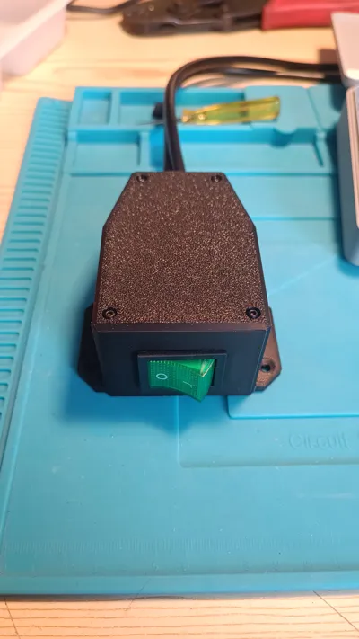
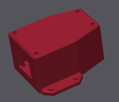
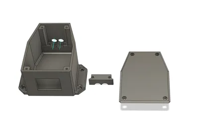
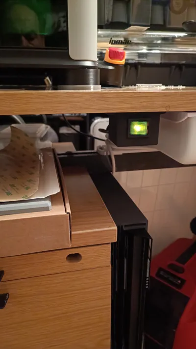
I find it inconvenient to always have to reach to the back to turn off the printer, so I designed an under-table switch box. The switch is discreet, takes up no space on the table, and you can conveniently turn the device on and off from the front. The housing can, of course, also be used for other devices or machines
!!! Warning!!! ⚡230V⚡
If you are not familiar with electrical wiring, you should have the wiring done by a professional!
I assume no responsibility for any damages!
Boost Me (for free)
If you like my work, please give me a boost here!
Material list:
Recommended filament 1 or filament 2
1 x rocker switch 230V / 16A / 4-pole or rocker switch 230V / 30A / 4-pole
4 x flat connectors
4 x BT 2.5x8
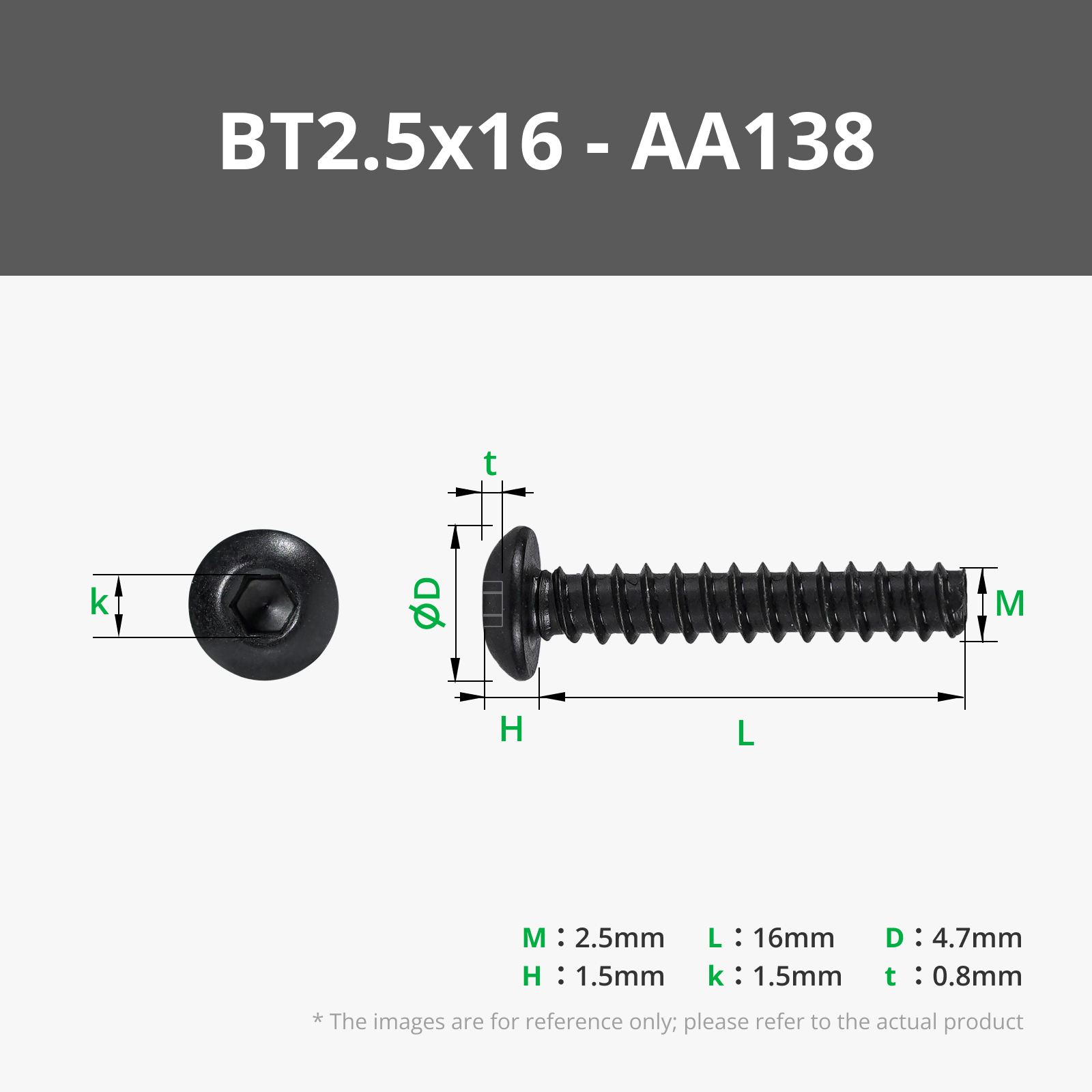
2 x BT 2.5x16
1 x connecting cable of sufficient length (or 2 short ones)
Assembly instructions:
Cut the cable at the appropriate spot, or cut off the unnecessary plug from the short cables

Push the cut ends through the two rear holes and the front hole and strip the ends

Crimp the appropriate flat connectors onto the four conductors and plug them onto the switch contacts. Observe the wiring diagram of the plug!


Push the plug into the opening with some pressure until it locks into place and connect the ground conductors with a Wago terminal block

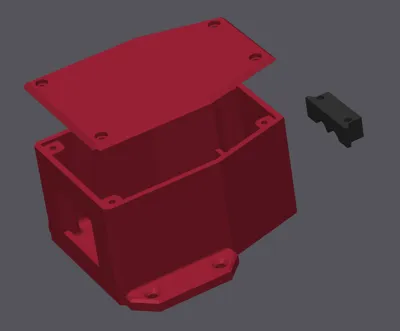
- Secure the cables at the back with the holder and the two BT 2.5x16 screws
Screw on the cover, plug the connector into the socket, and check with a multimeter at the other connector if it is properly wired and if the indicator light illuminates when you switch to ON

- Unplug the cable from the socket and mount the box in a suitable location
- Connect the cable and rejoice, for you have succeeded!!!
License
You shall not share, sub-license, sell, rent, host, transfer, or distribute in any way the digital or 3D printed versions of this object, nor any other derivative work of this object in its digital or physical format (including - but not limited to - remixes of this object, and hosting on other digital platforms). The objects may not be used without permission in any way whatsoever in which you charge money, or collect fees.
Comment & Rating (0)