Prize Machine


Print Profile(1)
Description
This is a lottery machine
Before you begin, please read the instructions below and check the parts list to ensure all components are available before printing
Update:
2026.1.27
The material list has been updated and is located in the 'New Folder' at the very bottom. Since Excel files cannot be directly imported, it's placed there
First, let's prepare the parts. The required parts are as follows:
Boost Me (for free)
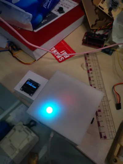
Printed parts (main body, top cover, light shield), RGB LED ring (24 LEDs, with VCC, GND, and OUT ports), Nano main controller, OLED display (with 4 I2C interfaces), button (with VCC, GND, and OUT ports), several female-to-female jumper wires, 3 male-to-female jumper wires, glue (any type that can bond)

2. Install the display screen
Connect 4 female-to-female wires to the 4 protruding ports on the back of the display screen and set it aside. Then take out the main body and remove the supports, but you don't need to remove all of them, just enough to allow the wires to pass through

Finally, thread the wires from the display screen, which was set aside, through the hole from the top and pull them out from the other end

Note⚠️: It's okay if the display screen's angle is not correct now; you can adjust it when gluing, and the same applies to subsequent steps
3. Install the button
Connect three female-to-female wires to the three ports on the button, then insert the button into the side hole and put the wires inside the main body (no need to glue yet, it will be glued later)

(It's okay if it's crooked, it will be fine once glued)
4. Install the LED ring
The LED ring has two ports; do not use the recessed ones, use the protruding ones. Then insert 3 male-to-female wires into the protruding ports, with the male end inserted and the female end outside. Then pass the two wires through the hole in the top cover, and then snap the LED ring into place, like this:

5. Wiring
Wiring is a relatively difficult operation, so I will draw diagrams and provide images below (it is recommended to insert the main controller before wiring):
Pin 2 — Button N
A SCL — SCL
Pin 4 — LED strip N I2C interface SDA — SDA
O 5V — VCC
Main GND — GND
Controller
(The pins are labeled on the button, LED strip, and display screen; just connect them accordingly)

6. Testing
To prevent program failure after gluing, we will conduct a test:
Scroll to the end and open the 'New Folder' folder;
Open the program on your computer;
Connect the Nano version's Type-C interface with a data cable, plug it into the computer, connect the device, and upload the program;
Test for success
7. Secure and test
Apply glue where you deem necessary, just make sure it's firmly attached
8. (Optional, Recommended) Add a light shield
This step is optional. However, it is recommended as it covers the individual small LEDs on the light ring, making it more aesthetically pleasing; it also shields the light, preventing the emitted light from being too dazzling. The cover and other sections also have light shields added. The operation is very simple; just use glue to attach the light shield
9. Done!

Boost Me (for free)
Boost Me (for free)
This was not easy to make, it was planned for a long time and built step by step. Please send a rocket~
If you encounter any problems, please leave a comment in the section below and indicate which step it concerns at the beginning. If you need a parts shopping list, just type 'I need a parts shopping list' in the comments section
Note: A1 mini currently cannot print this, as it won't fit on one plate. Files adapted for A1 mini will be uploaded later.
Comment & Rating (0)