
Dynamic Walker: Physics Experiment for All Ages!

Print Profile(2)


Bill of Materials


- rubber pad or balloon x 1: rubber pad or balloon for surface roughness
Description
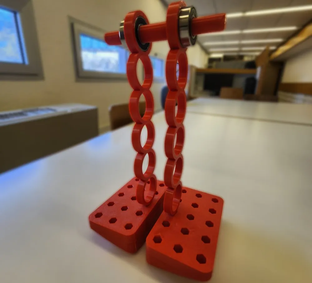
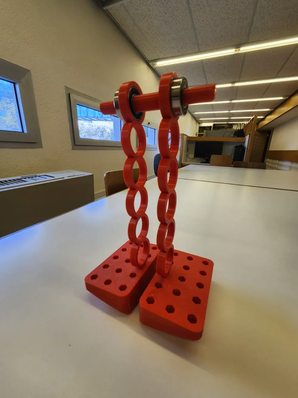
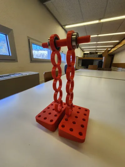
Experience the wonder of physics and biomechanics with this 3D-printable Passive Dynamic Walker!
Perfect for all ages, it showcases principles like the center of mass (COM), pendulum and inverted pendulum motion, and their connection to walking gait and friction. Ideal for classrooms, makerspaces, or hobbyists, this walker relies solely on gravity to “walk” step by step down a slight slope, demonstrating dynamics, stability, and motion studies with minimal materials and setup.
Use the included CAD model to experiment with changes in part density or dimensions, and compare theoretical COM predictions to real measurements. I've also written a detailed guide on lab activities and the physics behind its movements, be sure to check it out!
OnShape Model: Link
What Is a Passive Dynamic Walker?
A passive dynamic walker is a mechanical device that replicates natural walking with no external motors. By precisely balancing the center of mass and moment of inertia, it reveals how stability and movement interact. This model lets users explore friction, COM placement, weight distribution, and other factors influencing gait.
Printing & Assembly Instructions
- Prepare Materials:
- PLA filament for printing.
- 4 * 6001 bearings (two for the main hip joint, two for shifting COM).
- Optional but important: Rubber sheets, friction pads, or balloon material for the feet.
- Print the Model:
- Use the provided STL files.
- Follow recommended print orientations for optimal walking performance.
- Assemble the Walker:
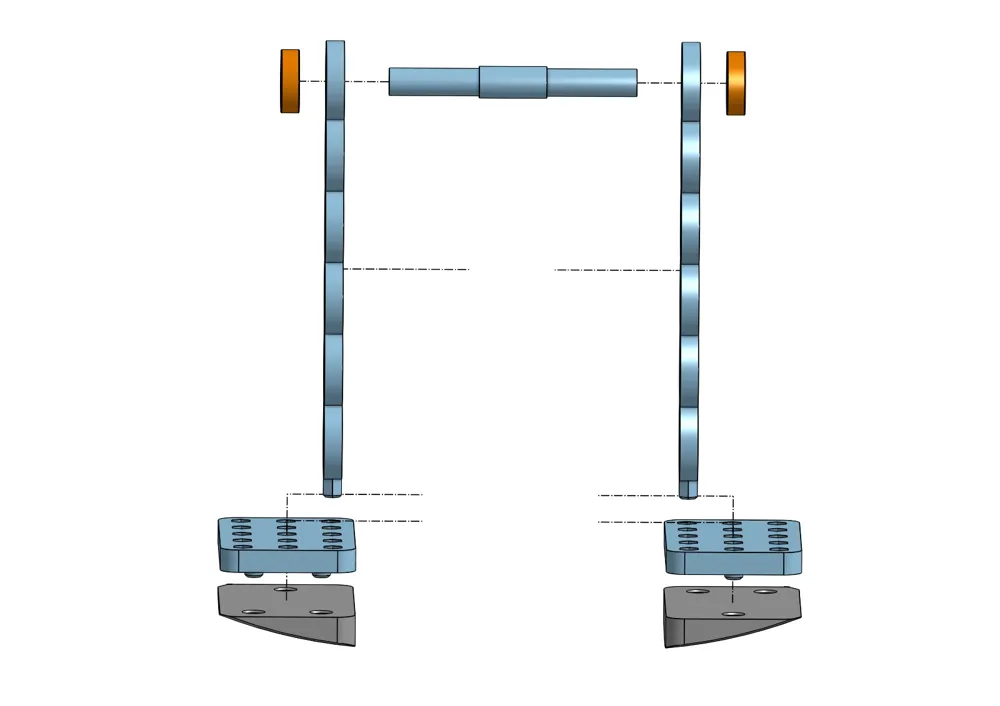
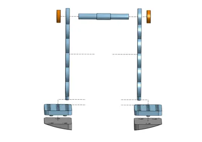
- Use the exploded view i made of the Walker, also, you can use the assembly in the OnShape page
- Insert bearings into the shaft and leg holes.
- Adjust COM by relocating bearings or adding extra ones.
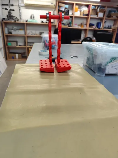
- Glue friction pads on the feet if desired or wrap a balloon on the foot. Alternatively, put a friction mat on the walking surface.
- Test It Out:
- Experiment with different angles, weight placements or friction surfaces and note any changes in gait.
Suggested Lab Activities
Begin by showing the students human stance phase. The YouTube video is a good place to start. Let them walk and see and feel the different phases of walking:
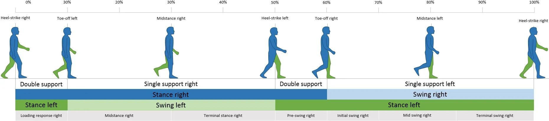
human gait cycle - showing the stance and swing phase of the human walk (from: https://www.physio-pedia.com/The_Gait_Cycle)
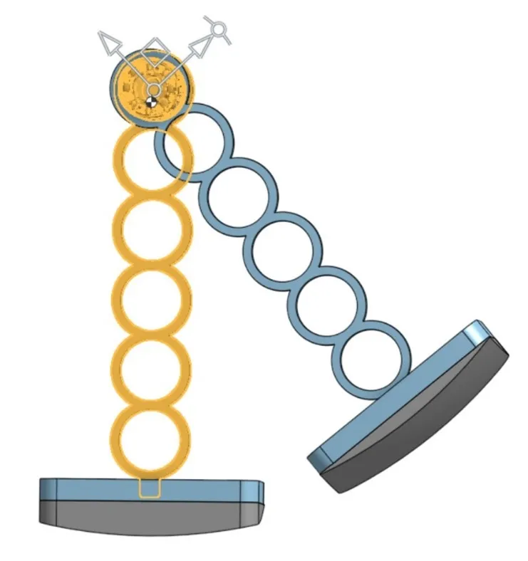
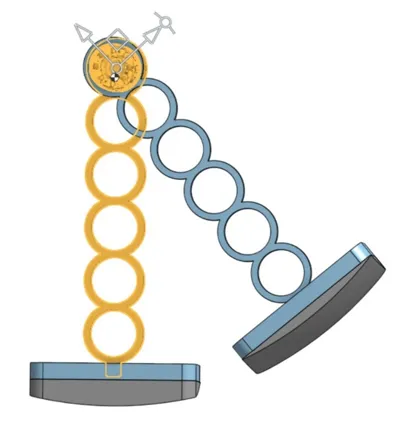
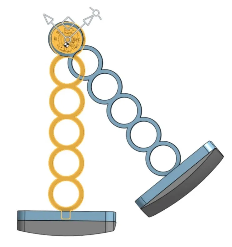
Using simplification we can say that during the stance phase of each leg, the COM of the body can be looked at as a point mass and as a result the movement can be looked at as an inverted pendulum. When a leg is in a swing phase, the movement can be looked at as a pendulum motion. Can also be shown using OnShape, when putting one leg up and one down and seeing the COM shift to the upper part making it similar to an inverted pendulum and see the change when changing between them as shown below:
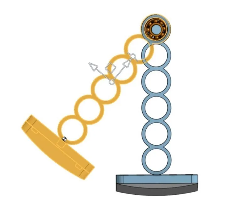
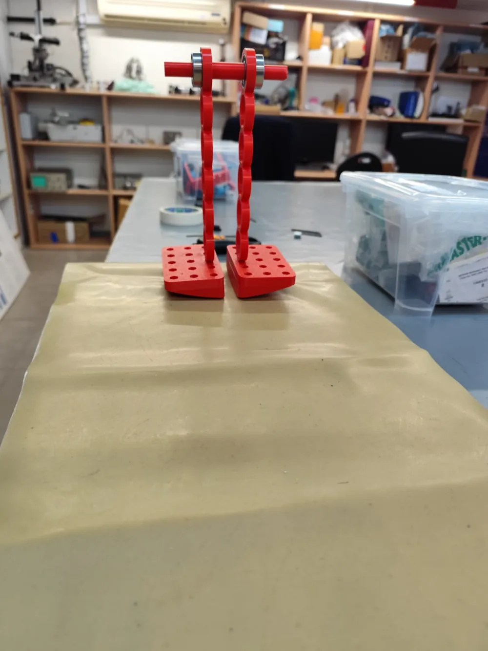

Now, when you look again at the OnShape model, you can see that the foot is shaped like a cut sphere, the reason for that is because the passive walker does not have a hinge as in a knee, therefore, to make the walker change between stance phase of each leg, it has to be able to tilt sideways, so the other leg can swing and cross it. It can be easily seen in the gif provided here:
For those who want to dive deeper, i included some more detailed explanation about the Kinematic Model, Motion Analysis and some calculations i made using the passive walker using tracker, in the attached pdf file.
Now that we understand the basic physical concepts of the walking gait of the human body and the passive walker, we can go on to trying it ourselves.
Its time to start printing and have some fun. Print using the printing profile i uploaded.
assemble the walker according to instructions provided here. Make a platform for making a sloped surface, you can use any flat surface and something under it.

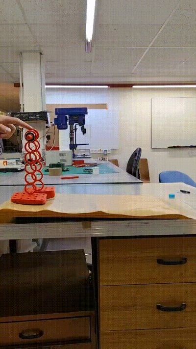
Now let the walker start walking without adding any friction under it.
You will see that does a strange movement, which will look a little like dancing. This happens because the friction is what is making it closer to a pendulum/inverted pendulum, as lets the foot make a rolling without slipping movement which in this case makes it act like a hinge movement, which lets it act closer to an inverted pendulum. Also it prevents it from slipping sideways and rotations around the leg's axis, letting it move in a more straight line, and also making the sideways rolling movement more “smoothly”.
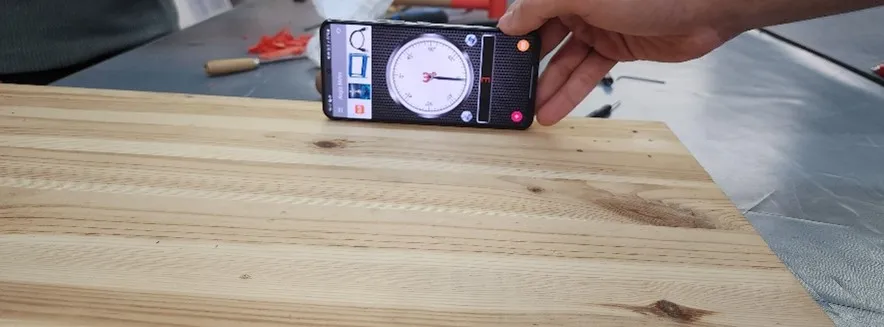
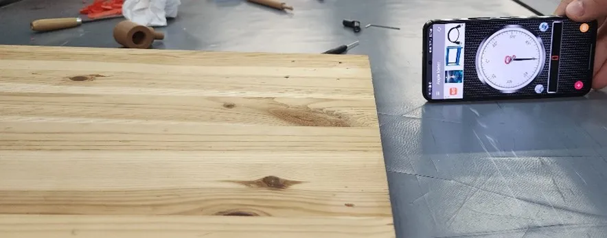
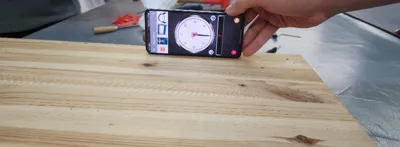
Explain the importance of setting a reference when measuring in general, by measuring the reference surface angle and then the sloped surface angle( angle between 1-3 degrees will work best according to relevant articles, 3 degrees worked best for me).
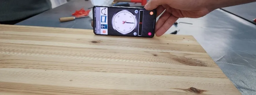
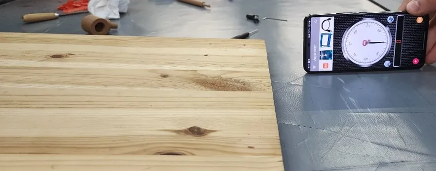
Weigh individual parts (legs, feet, shaft). In the “display mass and section properties” measurement tool on the lower right screen, after selection the part you want, you can check the part's volume:

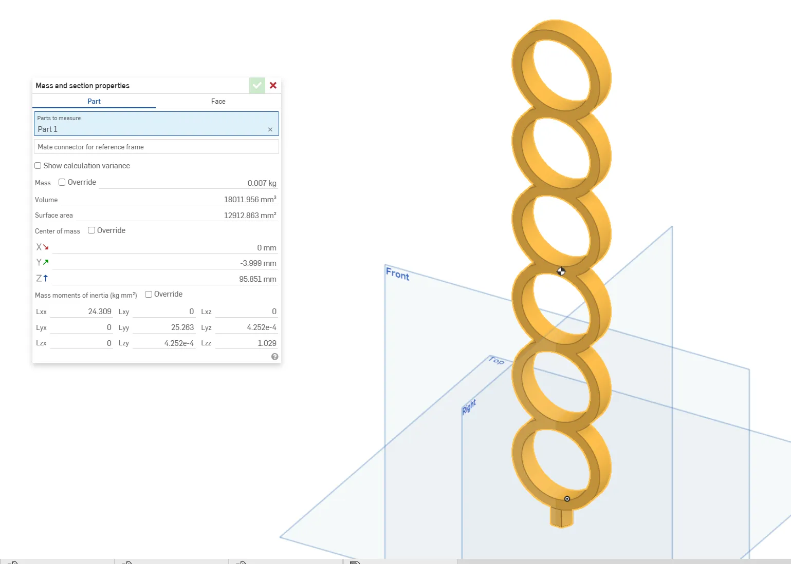
After that you can enter the material of the part:
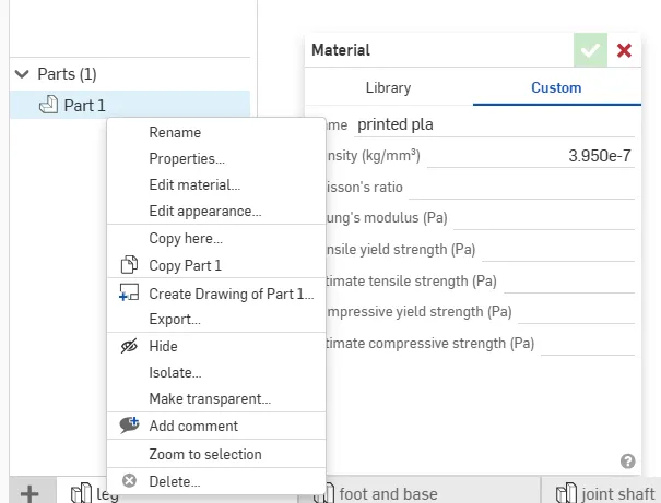
and change the density value to the mass weighted divided by the volume.
Now after changing it for each part you can see the COM when getting into the assembly and using the “display mass and section properties” measurement tool
Also, using the COM measurement you can view how it shifts to the shaft during the swing phase and then to the foot during swing phase (again make sure to choose the whole assembly and then use the “display mass and section properties” measurement tool.
The COM appears as a black and white circle
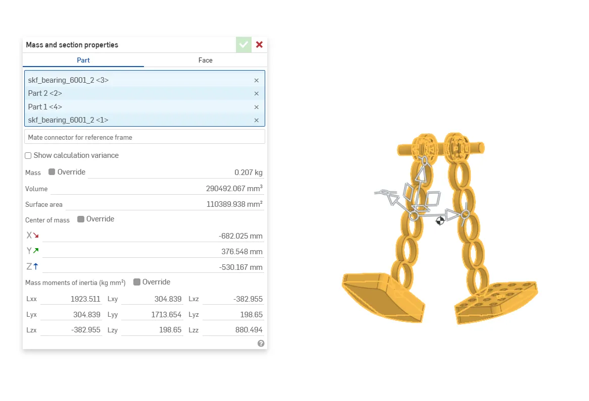
To show that the during swing the COM moves to the upper part, we will need to deselect all the parts that are not the leg, foot and foot base, as we say their effect is negligible as they are a Stationary support, which for this is a good assumption, the same for the stance phase.
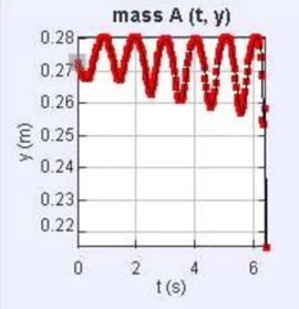
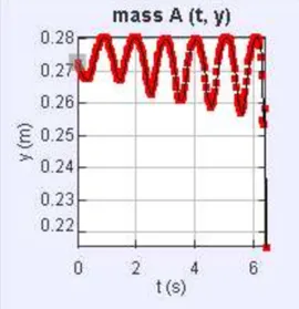
For a move graphical simulation of the pendulum movement, you can see the oscillation using Tracker rand measure how the oscillation amplitude becomes larger each step, as the walker gains energy with the conversion of gravitational energy into kinetic energy.

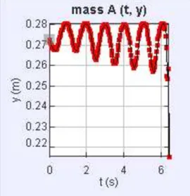
Disclaimer: I am a ME student, and this work is based on my understanding from what I have learned in Biomechanics class and the articles I have read about it. Please use this information at your discretion.
Boost Me (for free)
A boost is free! and will help a lot :)
Documentation (1)
License

You shall not share, sub-license, sell, rent, host, transfer, or distribute in any way the digital or 3D printed versions of this object, nor any other derivative work of this object in its digital or physical format (including - but not limited to - remixes of this object, and hosting on other digital platforms). The objects may not be used without permission in any way whatsoever in which you charge money, or collect fees.


Comment & Rating (12)