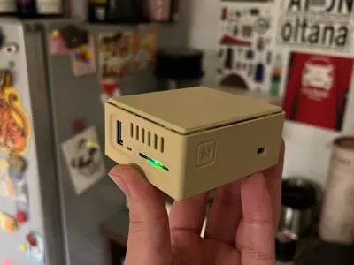
Modular Version of the H29K Enclosure


Print Profile(4)


Description
Boost Me (for free)
If you think the enclosure is good, please boost me~
Please do not modify this model without authorization, or print it and sell it on a second-hand platform. Please respect the community's open-source protocol and the original author. Thank you very much for your cooperation.
202504 Added two antenna-compatible accessories (optional print)
- Added 4-in-1 ceramic antenna top cover, requires two additional m2x4 screws
- Added 4-in-1 PCB antenna enclosure, good signal gain effect, but requires finding PCB design files yourself. After ordering the free PCB antenna from JLCPCB and receiving it, embed it in the enclosure for a complete print, then solder the antenna feed lines for assembly. Can be 3mm thinner overall, perfectly balancing appearance integrity and signal. [Tip: This kit needs to be printed together with the antenna, it cannot be assembled after getting the free enclosure from JLC, recommended for friends with 3D printers to make it themselves, finished product order link, on Goofish: @随时发疯]

202503 Fine-tuned some details, version updated to v2.1
Changes:
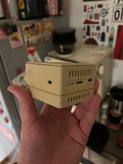
- Adjusted some opening sizes for a better fit and easier SMA antenna installation
Adjusted toggle switch details

- Added a middle frame with an sealed opening, convenient for attaching patch antennas, now allows for a circular antenna placement method. (recommended for use with CNC bottom shell)
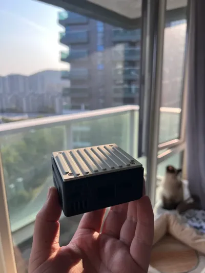
202503 Added JLCPCB CNC heat dissipation bottom shell, battery, and external antenna top shell
Manufacturing method:
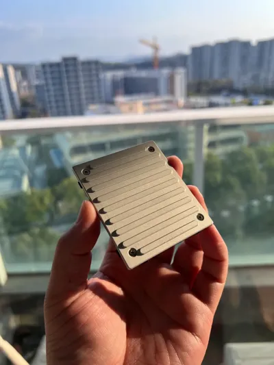
- Download files 'Metal Heat Dissipation Bottom Shell Component A-CNC Heat Sink' and 'Metal Heat Dissipation Bottom Shell Component B-Frame'
- Upload 'Metal Heat Dissipation Bottom Shell Component A-CNC Heat Sink' to the JLCPCB 1-yuan CNC page, priced at 1 yuan + shipping, totaling around 6 yuan, wait about a week for delivery
- 3D print 'Metal Heat Dissipation Bottom Shell Component B-Frame'
- After arrival, use four M2x4 screws for assembly and fixing, paste thermal silicone pads, then install
Materials preparation:
- Thermal silicone pad, 5.5mm thick, one piece; 9.5mm thick, one piece. Each needs to be cut into a 3x4cm piece for thermal conduction to the CNC enclosure
- M2 flat head screws four pieces, length 4
Note:
- Because the 'CNC heat dissipation bottom shell' occupies part of the original 'patch antenna shell', if you plan to use a battery, it is recommended to download the 'Battery and SMA Antenna Top Shell' to externalize the antenna; or choose the combination of 'Middle frame logo seal' and 'Battery top cover' for an internal patch antenna.
202502 Updated v2.0 modular fully customizable version:
- Previously, some players took it to JLCPCB for free 3D printing, and due to the strength of the resin, some parts of the enclosure's structure could easily crack when screwing. The new version minimizes the use of screws
- Based on the old version, model details were optimized, hole positions were adjusted for accuracy, and some heat dissipation holes were added. The current battery version is not only 4mm shorter than the original, but the antenna fixing method is also simpler
- Optimized printing parameters to improve the printing fineness of the enclosure
- Added some details, now it looks more refined
- This major version iteration fully modularizes the enclosure, the upper and lower parts are entirely up to your choice. You can choose to add a fan base module to cool your 29k, or choose an external antenna module to enhance your signal
Your CPE will be completely defined by you!
Features:
- Modular design, customizable components
- Can actively or passively dissipate heat
- Compatible with battery and non-battery versions
- Friendly size, free from JLCPCB
You need to prepare:
Screws: 1) M2x5 screws 1 piece
Antennas: 1) Patch antenna 59x9 ipex 4th generation feed line 13cm 4 pieces or 44x10 ipex 4th generation feed line 13cm 4 pieces , and 44x10 ipex 1st generation feed line 6cm 2 pieces
2) SMA antenna self-prepared, recommended length no less than 10cm
- Fan: Sunon 4010 fan (when you use the fan base and fan top cover kit)
- Display screen: 1.19 inch display 8pin extended cable (when you use the screen top cover kit)
- Heat sink: Aluminum alloy heat sink 30x40x5 for SoC cooling. (when you use the passive cooling enhancement kit, you can install heat sinks for both the module and the SoC)
- Other accessories: Silicone foot pads 10mm diameter 1.5mm thickness and up
- If you need a proxy printing service, you can contact group members for help, Goofish@随时发疯, do not give resellers any opportunity
Suggested combinations:
With battery:
- Battery top cover + middle frame + fan base
- Battery top cover + middle frame + passive cooling enhancement base
- Other combinations… (The latest version limits charging power, so the bottom shell does not necessarily require an enhanced heat dissipation base)
Without battery:
- Built-in fan top cover + middle frame + patch antenna bottom cover
- External antenna top cover + middle frame + patch antenna bottom cover
- Screen top cover + middle frame + patch antenna bottom cover (you can attach the antenna to the top)
- Patch antenna top cover + middle frame + patch antenna bottom cover
- Various combinations…
Files are A1 mini split plates; those needing combined plates should combine them themselves.
If the model has helped you, please give me a like or a boost. Thank you very much!
License
You shall not share, sub-license, sell, rent, host, transfer, or distribute in any way the digital or 3D printed versions of this object, nor any other derivative work of this object in its digital or physical format (including - but not limited to - remixes of this object, and hosting on other digital platforms). The objects may not be used without permission in any way whatsoever in which you charge money, or collect fees.
Comment & Rating (2)