Bull Riding Machine for dummy 13


Print Profile(1)

Bill of Materials

Description
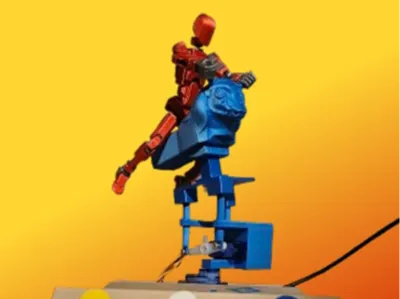
3D-printed Bucking Bronco for Dummy 13 with Servo Control and ESP32
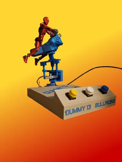
Welcome to my 3D-printed bucking bronco project, a delightful fusion of fun, technology, and movement! This project employs an ESP32 to govern two servos for rotation and bouncing—ideal for small dummies designed to mimic the thrill of authentic rodeo riding.
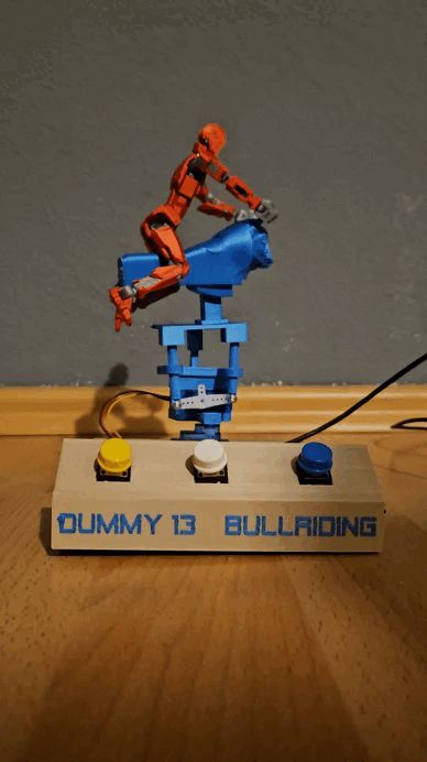
- Dynamic Control: Three push buttons offer varying speeds:
- Gentle: For a leisurely rodeo experience.
- Wild: For seasoned riders.
- Crazy: For the ultimate adrenaline rush!
- Unending Excitement: The rodeo remains captivating with randomized target angles and velocities.
Materials Required:
Electronics:
- ESP32
- Two Servos
- Three Micro Push Buttons
- Jumper Wires
- USB Cable for Power Supply
- (I also use an on/off switch here)
- Software:
- Arduino IDE
Utilizing the provided sketch allows for straightforward ESP connection. Otherwise, ensure correct pin assignments.
Connection Diagram
USB Power Supply (Central Source):
- The USB port provides 5V and GND.
- +5V from USB is directly channeled to the servos (VCC) and the ESP32 (5V).
- GND from USB connects all components:
- ESP32
- Servos
- Push Buttons
- Servos:
- VCC (Positive) of all servos: Directly connected to 5V from USB.
- GND (Negative) of all servos: Directly connected to GND from USB.
- Signal Lines: Control movement:
- Servo 1 (Bounce): Signal → GPIO 23
- Servo 2 (Rotation): Signal → GPIO 22
- Push Buttons:
- One pin of each push button is connected to GND.
- The other pin of each push button is connected to an ESP32 GPIO pin:
- Push Button 1: GPIO 15
- Push Button 2: GPIO 4
- Push Button 3: GPIO 5
- The ESP32's internal pull-up resistors ensure that the GPIO pins remain HIGH in their resting state.
- ESP32 Power Supply:
- The ESP32 receives power directly via the USB port.
- No additional connection to VIN or other pins is necessary.
Documentation (1)
License
You shall not share, sub-license, sell, rent, host, transfer, or distribute in any way the digital or 3D printed versions of this object, nor any other derivative work of this object in its digital or physical format (including - but not limited to - remixes of this object, and hosting on other digital platforms). The objects may not be used without permission in any way whatsoever in which you charge money, or collect fees.
Comment & Rating (2)