
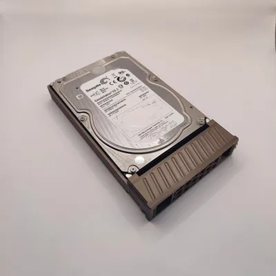
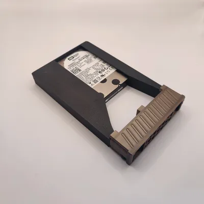
Tool-less 3.5" HDD Caddy for Supermicro Servers



Print Profile(5)



Description
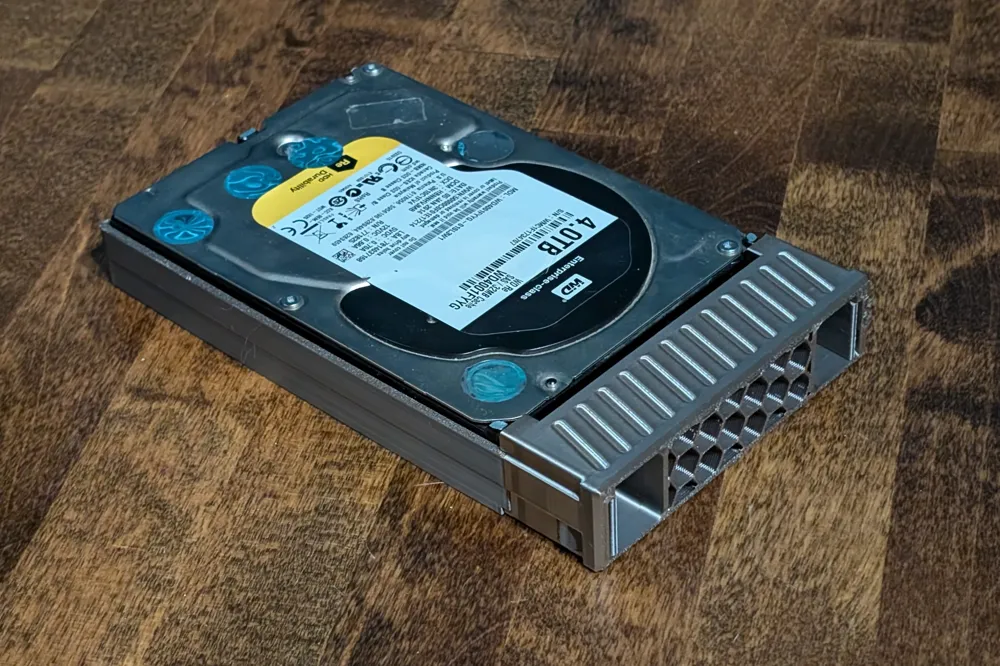
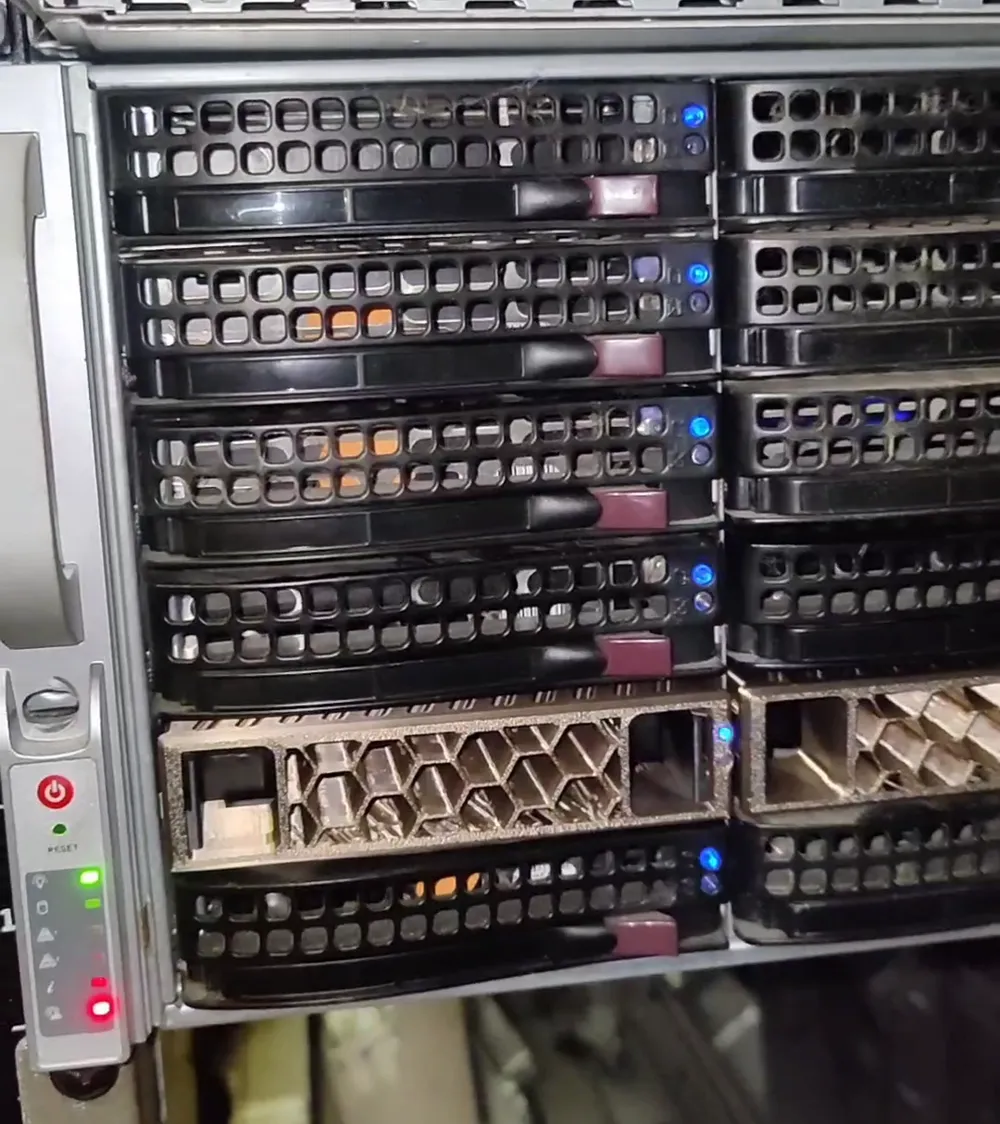
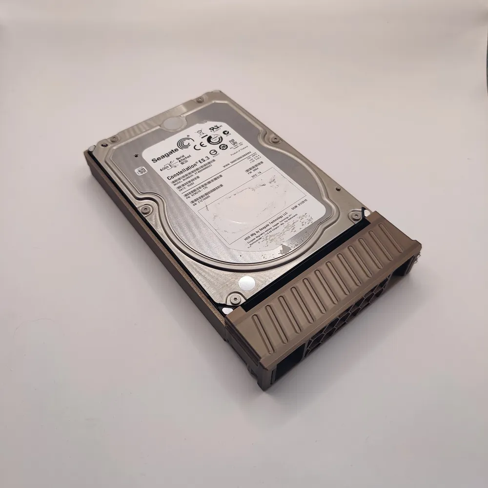
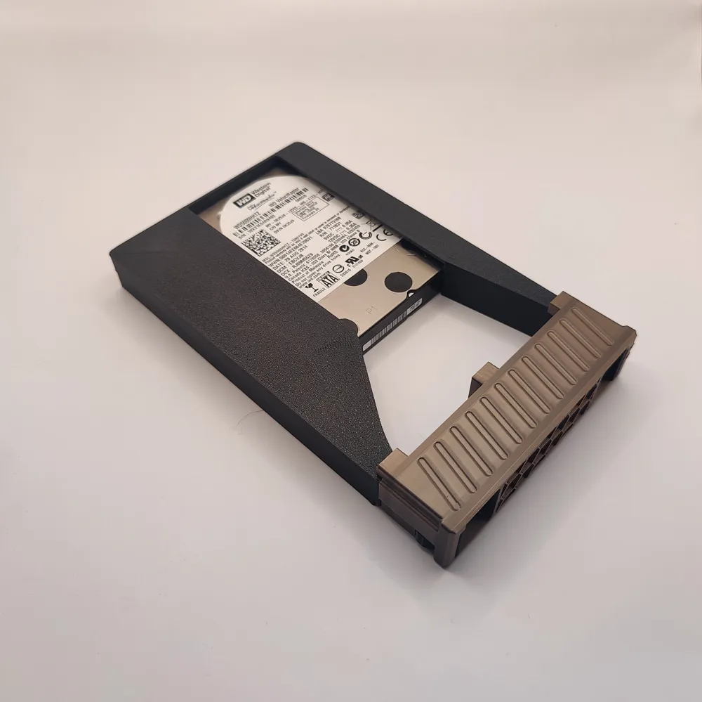
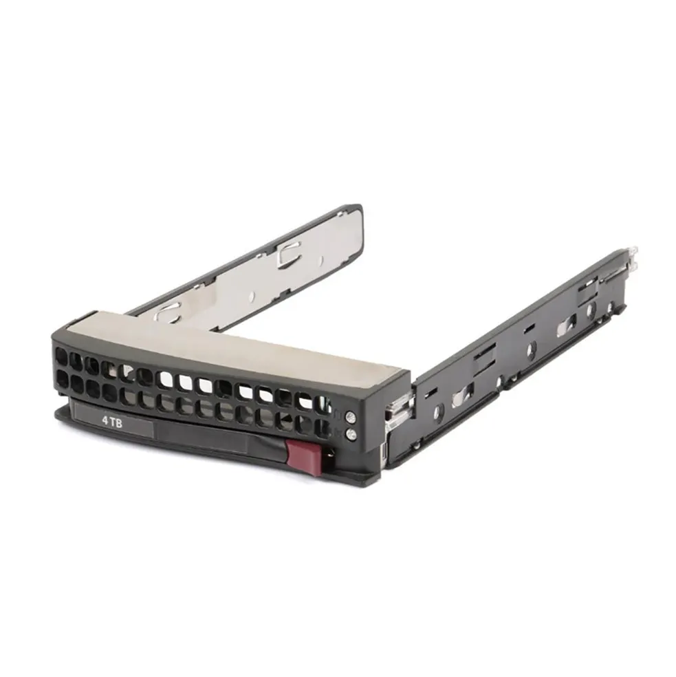
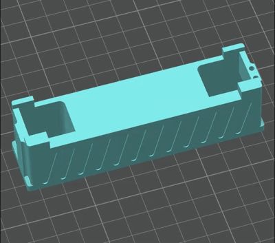
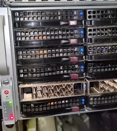
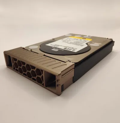
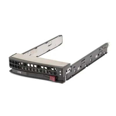
Designed for the older generation but ubiquitous Supermicro Caddies. Part # SC93301 or MCP-220-00075-0B
HDD Status LED's are functional with additional 2mm fiber-optic cable. I've used THIS by searching "fiber optic 2mm"
I have a pair of cables in the caddy face and a pair in the sled so they are separate.
You could try using a transparent PETG or PC filament instead of the fiber optic cable but the status LED might not be as bright.
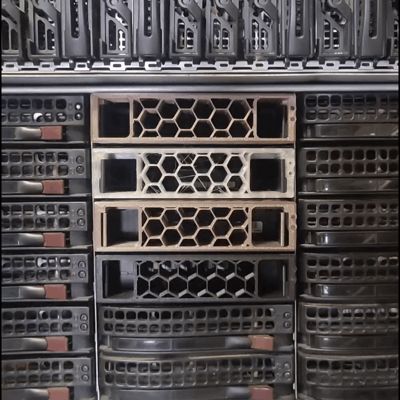
Also, you could probably print the caddy face in different colors to designate specific HDD's or different HDD pools.
Depending on how hot your HDD's are, you may want to use a different filament other than PLA because of PLA's low deformation temperature
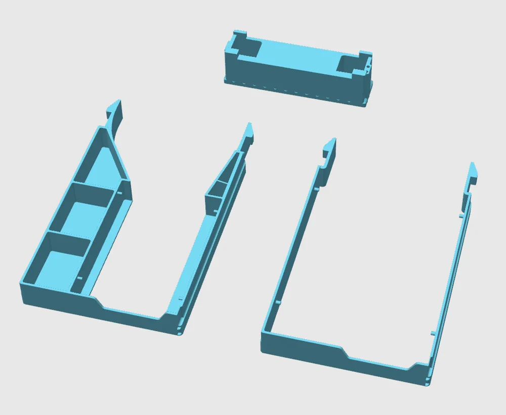
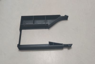
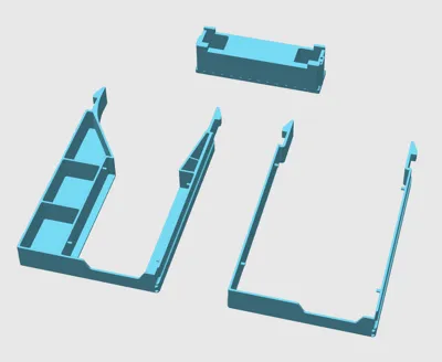
To split the model into each individual object:
(In slicer) Right-click model → split → to object


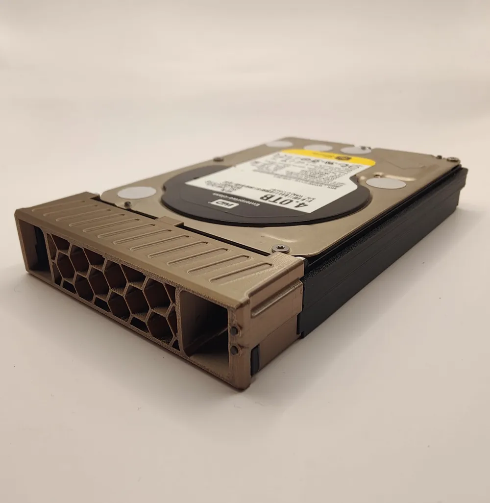
The ventilation holes for the front of the caddy are created within the slicer. That way you can customize and change the ventilation holes however you want to the limit of your slicer.
REQUIRED slicer settings for vent holes:
| Top Shell Layers | 0 |
| Bottom Shell Layers | 0 |
These specific settings basically removes the top and bottom layers of the model which will reveal the infill pattern. The infill pattern itself IS the ventilation hole pattern. My settings below will create the pattern seen in my pictures but you can change it to be whatever pattern you want from your slicer.
PRINT SETTINGS I'VE USED:
Nozzle: 0.4mm
Layer Height: 0.2mm
(Feel free to experiment and change what you like)
Any setting not listed below are assumed to be default
| 3.5" Caddy Face | ||
| Walls | 2 | |
| Top Surface | Concentric | |
| Top Shell Layers | 0 | required for visible infill pattern |
| Bottom Surface | Concentric | |
| Bottom Shell Layers | 0 | required for visible infill pattern |
| Sparse Infill Density | 8% | change to desired infill pattern |
| Sparse Infill Pattern | Honeycomb | change to desired infill pattern |
| Infill Direction | 60 degrees | change to desired infill pattern |
| Enable Supports | Yes | possibly needed for grill snap-fit |
| Type | Normal Auto | |
| Style | Snug | |
| 3.5" Sled | ||
| Walls | 5 | |

| Enable Supports | Yes | possibly needed for tool-less studs & grill snap-fit |
| Type | Normal Auto | |
| Style | Snug | |
| Threshold Angle | 10 Degrees | to prevent generated supports in fiber-optic holes |
| Brim Type | Outer Brim Only | for bed adhesion |
| 2.5" Adapter Sled | ||
| Walls | 3 | |
| Top Shell Layers | 1 | to reduce filament |
| Top Shell Thickness | 0.4mm | to reduce filament |
| Bottom Shell Layers | 1 | to reduce filament |
| Enable Supports | Yes | possibly needed for tool-less studs and grill snap-fit |
| Type | Normal Auto | |
| Style | Snug | |
| Threshold Angle | 10 Degrees | to prevent generated supports in fiber-optic holes |
Current Version: v1
**It's possible that different versions of Supermicro chassis may be incompatible with this model. Result may vary**
License



Comment & Rating (33)