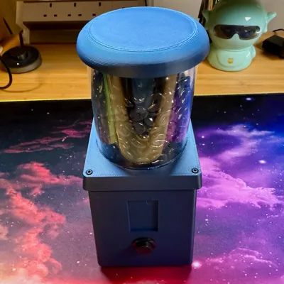
Toy Coffee Grinder: now USB-C rechargeable


Print Profile(1)

Description
Here's my first model upload to Makerworld!
This totally unnecessary upgrade lets you use a Lipo battery and charging circuit board, so that you can really take your toy coffee grinding to the next level.
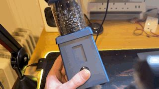
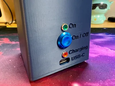
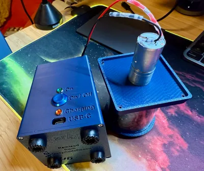
The original version uses a battery pack (4 x AA), which means to replace or recharge the batteries you would have to unscrew and remove the top for access. No more! This version you can recharge via the USB-C port on the back. I added a “On / Off” button, enabled access for the the USB-C charging port and broke out the power and charging LEDs.
Boost Me (for free)
Boost this, my first Makerworld model, if you want to encourage me to make more totally unnecessary upgrades!
Additional parts
- 3.7v 2000 mAh Lipo battery (£9 on Amazon)
- Pimoroni LiPo Amigo Pro charging circuit board (£8 from Pimoroni)
- A further 16 mm push button for “On / Off”
- Amber LED panel indicator (£0.80 on AliExpress, 3-6v Red) for “Charging”
- Green LED panel indicator (£0.80 on AliExpress, 3-6v Green) for “On”
- 2 x 100 ohm resistors, one for each of the positive (anode) legs of the 2 x LEDs above
- A bunch of white shrinking solder tube wire splice heat shrink things to connect wires (e.g. on AliExpress). White = "AWG 26-24", but I use them for a tight fit on 22 AWG wires.
Assembly
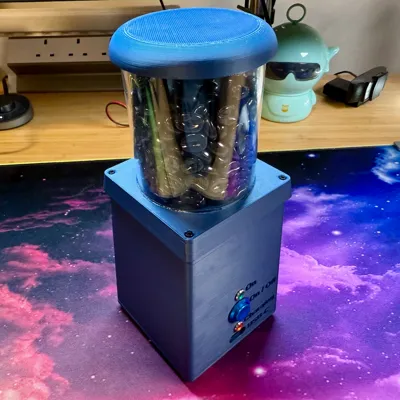
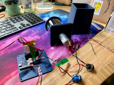
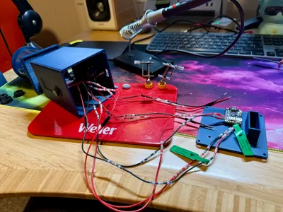
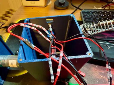
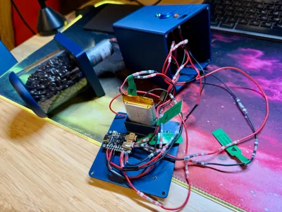
Refer to the original upload for the remaining parts and overall assembly instructions: grinder top (with motor attached underneath), plastic tube full of resin coffee beans, tube top. If anyone wants a circuit diagram, let me know. Here's a description. I suggest you use 20 cm lengths of 22 AWG red/black wire throughout.
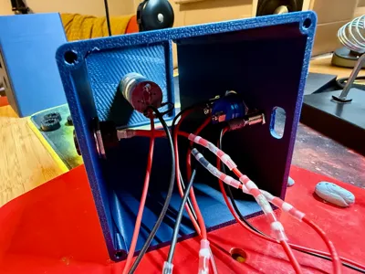
- Attach electronics to the case (sides). Attach red/black wires to front and read 16 mm buttons and the green and amber LEDs. Insert, then screw on the rear retaining nuts for the front 16 mm button, the rear 16 mm button, the On (green) LED and the Charging (amber/yellow) LED. Do this first, because if you solder the other ends of their wires, you won't be able to put on the retaining nut. Attach the motor to the base top that you printed, using the front-facing M3 screws.
- Solder 2 x pads on the Amigo Pro. Make sure you bought a Lipo battery with in-built protection. Solder across the pads on the Amigo Pro for FAST CHARGE to enable charging at 500 mA, much faster than the standard 200mA. Also solder across the pads for NO PROTECT, because the DC motor for the grinder has a 1.3A start/stall current, and otherwise the Amigo Pro limits its output to 1A.
- "On" LED: solder the anode of the green LED (with 100 ohm resistor attached) to the “ON” Plated Through-Hole (PTH) of the Amigo Pro. Solder the cathode of the LED to the “- in a circle" PTH.
- “Charging” LED: solder the anode of the amber LED (with 100 ohm resistor attached) to the “5V” PTH of the Amigo Pro. Solder the cathode of the LED to the “CH” PTH.
- "On / Off" button: solder the two wires of the additional (rear) 16 mm push button to the “SW” PTHs of the Amigo Pro. Note: this button is latched by the Amigo Pro.
- Connect the front 16 mm push button in-line to the positive, red, line of the motor.
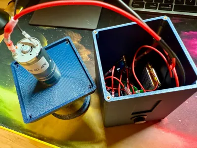
- Run the wires for the motor (negative from the motor, positive from one side of the front 16 mm push button) through the 3D printed “Sides” box, and out of the bottom, so that those wires are inside when you put the top tube with coffee beans on.
- Connect the motor, with the front push button controlling power, to the JST connector marked “Device” on the Amigo Pro. Check polarity i.e. where positive and negative go, since the JST connector wires I bought were the wrong way around.
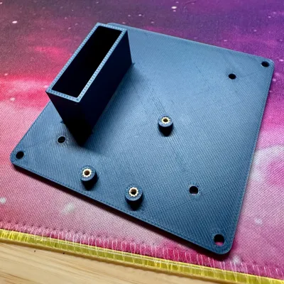
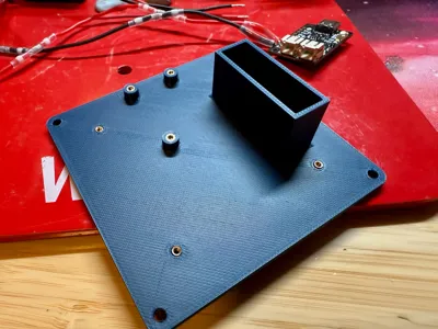
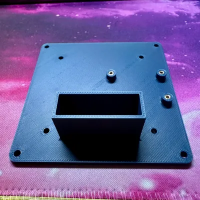
- Attach the Amigo Pro using using M2 screws, via its three corners, to the 3D printed stand offs on the base.
- Blu-tac the battery in its little holder box in case someone holds their grinder upside down.
- Connect battery to the JST connector marked “BAT” on the Amigo Pro. Check polarity: most Lipo batteries seem to come with the polarity the wrong (opposite) way around than needed by the Amigo Pro (see markings on the board). So, you need to cut the wires from the battery and reconnect them to the JST male connector the other way around (using the shrinking solder tubes). Connect the battery last to avoid having the circuit powered during the above.
Notes on the original instructions
The original model says “M2” in the description but “M2.5” in the materials for the grinder. I used M2 and then needed to add glue. I think the below would be better:
M2 screws and inserts for:
- Amigo Pro to base (4 mm long)
- Rubber feet (10 mm long)
M2.5 screw and inserts for:
- 4 x screws for top on to sides (12 mm long)
- 4 x screws for base up to sides (12 mm long)
I used a 130 rpm motor, but my version is definitely slower than in in the video for the original. The original may be more like 300 rpm.
I attached the rubber feet (from AliExpress) using M2 screws, washers and inserts. They're a little small, but work OK.
Other notes
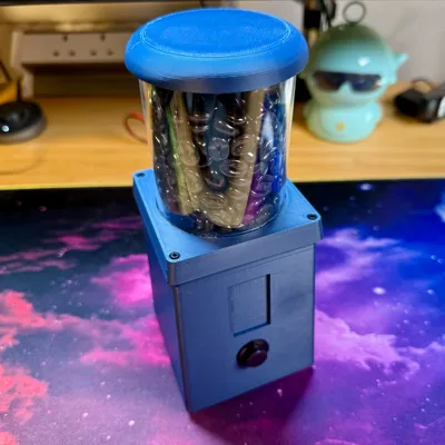
- Photos show the model without the 3D printed “chrome spout", because my silver filament hasn't arrived yet.
- I provided my Fusion 360 file (under STL/CAD files) if anyone can make use of it. The file's ended up quite a mess since I'm just learning the program.

Comment & Rating (1)