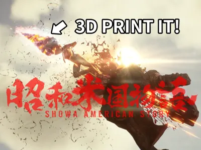
Showa American Story Protagonist Drill Weapon


Print Profile(1)

Bill of Materials


- 热熔胶 x 1: 用于固定电子配件
- 万能胶 x 1: 可以粘接PLA-PLA/PLA-PETG的万能胶(例如乐泰401)
Description
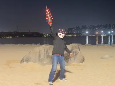
Welcome to the model page for the drill weapon wielded by the protagonist of "Showa America Story."
Inspired by the game's setting after watching the second PV in December 2024, I decided to create this drill weapon, meticulously recreating details from the PV before the game's release.
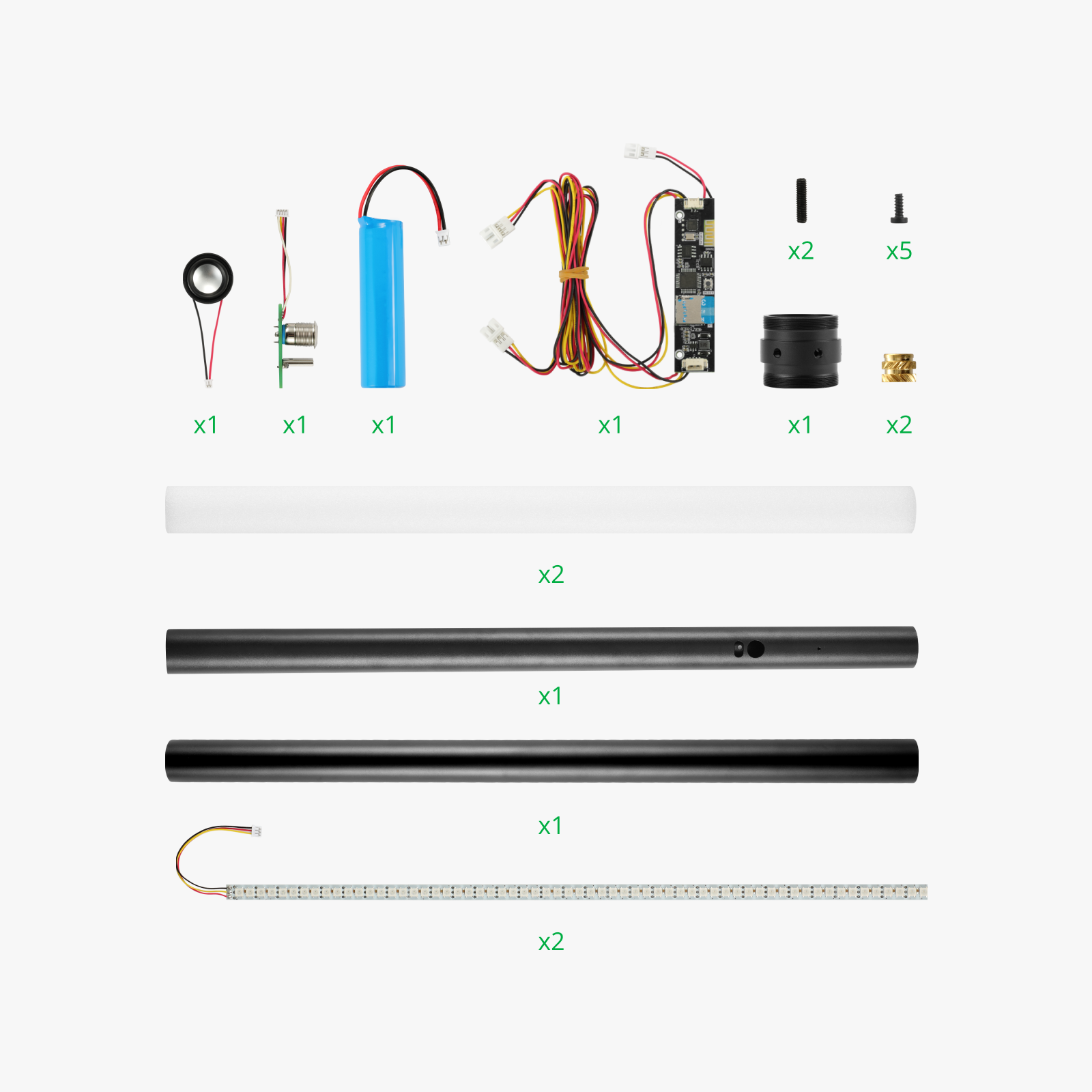
The model is optimized for the X1/A1/P1 series build plate dimensions and utilizes four filaments from Bambu Lab and one kit from Maker's Supply (listed above). Additionally, you will need two adhesives (listed above) to assemble the printed parts.
Assembly is straightforward, however, the kit is not inexpensive, and printing takes considerable time. I strongly recommend watching the Bilibili video → (https://www.bilibili.com/video/BV16i6xY1Eg7/) for a clear understanding of the model's structure before assembly. You can initially assemble without adhesive, confirming correct installation before using adhesive.
Written Assembly Instructions:
1. Align the two largest transparent PETG parts (filenames: Transparent1/Transparent2) from Plates 2 and 3 with the spiral direction and assemble them using four transparent pins and all-purpose adhesive;
2. Attach the remaining four transparent pins beneath this assembly and install Plate 3’s other transparent PETG part (filename: Transparent3), with the small-diameter circular face down, and the opening facing any direction;
3. Attach the Plate 1 parts (filenames: Shell1/Shell2) and the Plate 4/5 parts (filenames: Shell3-10) to the outer perimeter of the assembled transparent PETG components. All parts have foolproof designs; misalignments are readily apparent. After confirming the assembly, apply all-purpose adhesive to the seams;
4. Insert the two light strips from the Maker's Supply kit into the center of the assembled model, in a T-shape, with the wires exiting through the opening in the transparent part (filename: Transparent3);
5. Assemble the multi-color Plate 6 part (filename: Multi-color Base) to the model. Ensure the plug remains in the opening of (Transparent3) and does not exit through the through-hole of the multi-color base (as shown in Figure 1). Apply all-purpose adhesive to the seam after confirmation;
 ←Figure 1
6. Gently press the tail of the light strip shown in Figure 1 to ensure it is firmly seated, then secure the light strip assembly with hot melt adhesive. Install Plate 1’s part (filename: Handle) into the recess of the multi-color base, press firmly, and apply a suitable amount of all-purpose adhesive;
7. Take Plate 1’s (filename: Device Layer) part and install the electronic components from the Maker's Supply kit according to the correspondence shown in Figure 2. Secure with hot melt adhesive and interconnect;
 ←Figure 2
8. Lay the assembled model flat and insert the (Device Layer) into the (Multi-color Base), connecting the light strip and the mainboard's two sockets as shown in Figure 3;
 ←Figure 3
9. The top of the Device Layer part has raised installation aids; align these with the recesses above for installation. Observe the light strip wiring; if excess wiring is present, consider rotating the Device Layer 180 degrees until the wiring is neatly contained.
Enjoy~
Boost Me (for free)
Fellow enthusiasts, a Boost would be greatly appreciated~
Looking forward to the game's launch
License
You shall not share, sub-license, sell, rent, host, transfer, or distribute in any way the digital or 3D printed versions of this object, nor any other derivative work of this object in its digital or physical format (including - but not limited to - remixes of this object, and hosting on other digital platforms). The objects may not be used without permission in any way whatsoever in which you charge money, or collect fees.
Comment & Rating (1)