
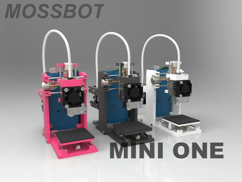
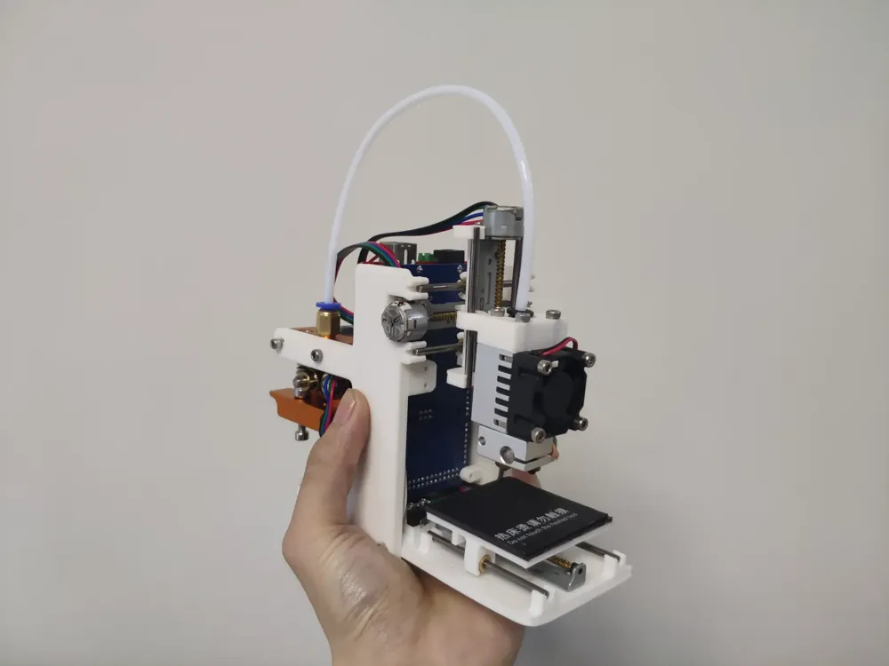
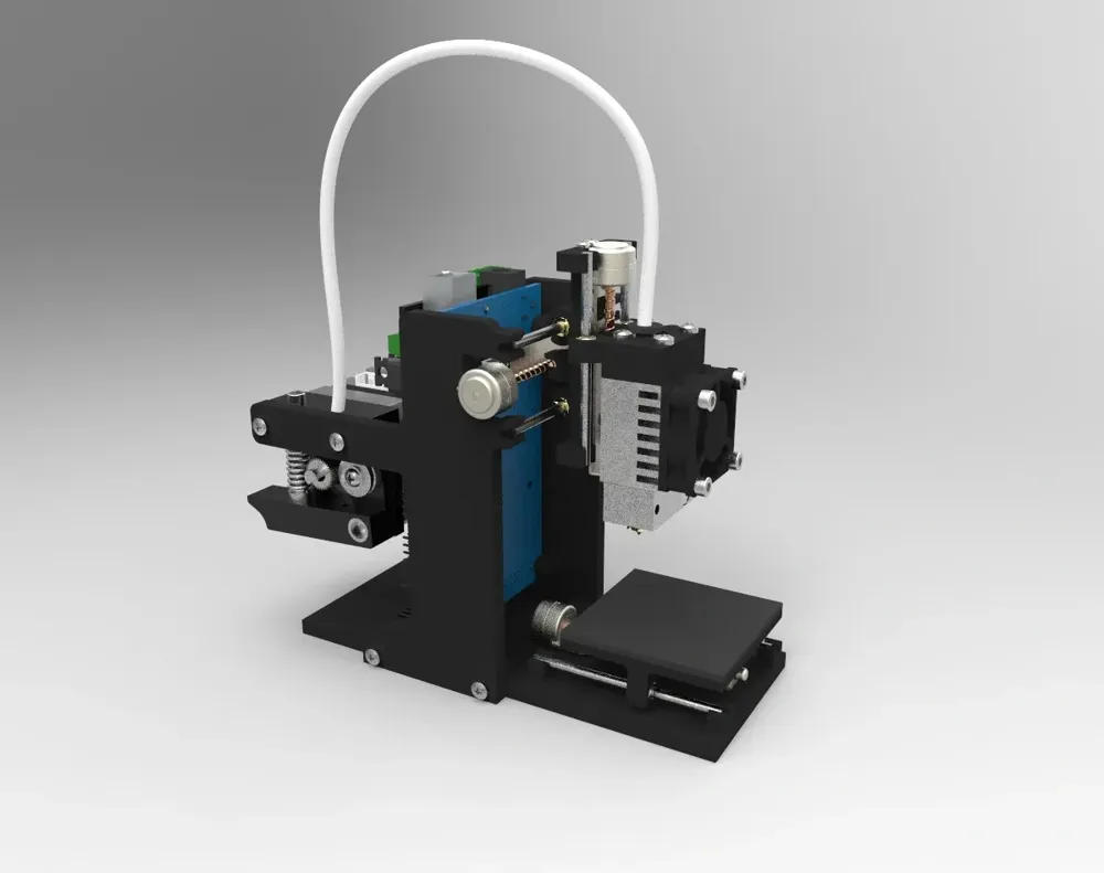
Original open-source mini one, the world's smallest palm-sized 3D printer
Print Profile(2)
Description
Project Introduction
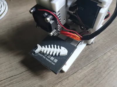
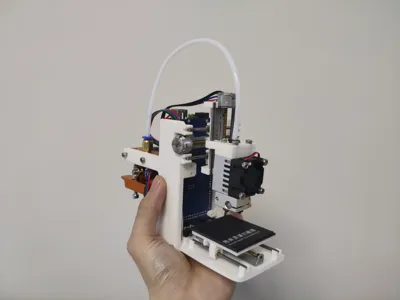
This is a pocket 3D printer developed based on Marlin firmware, using 10mm miniature lead screw motors. Due to the small printing area, the build plate uses a non-heated film, and the printing area is 45mm*45mm*45mm.
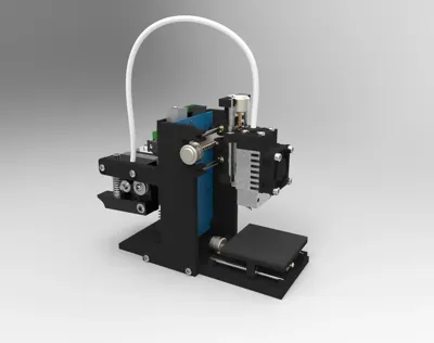
Original design drawings are provided for secondary modification and development.
Solidworks drawings: https://grabcad.com/library/mini-one-pocket-3d-printer-1
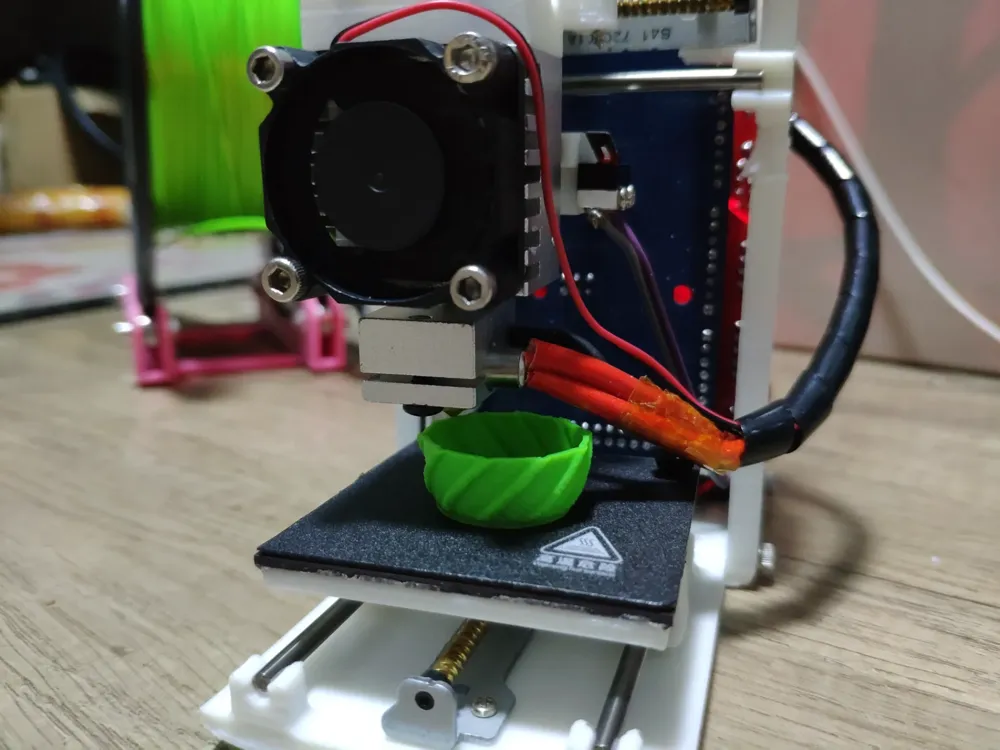
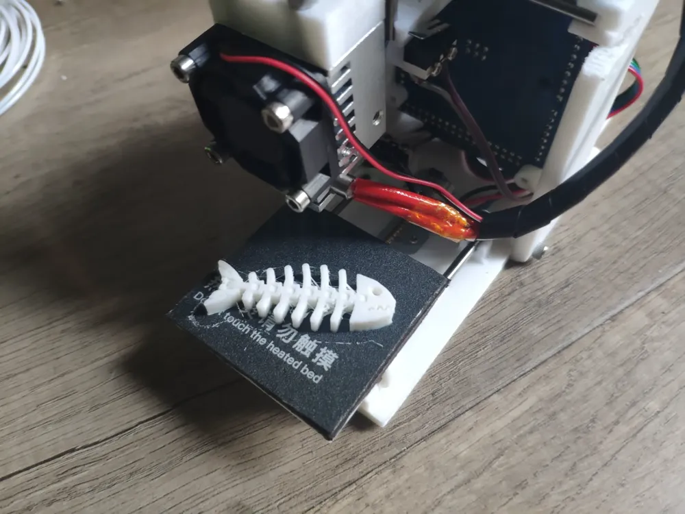
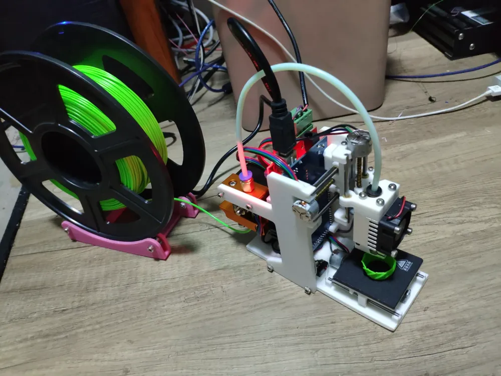
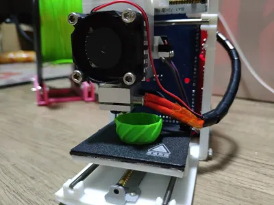
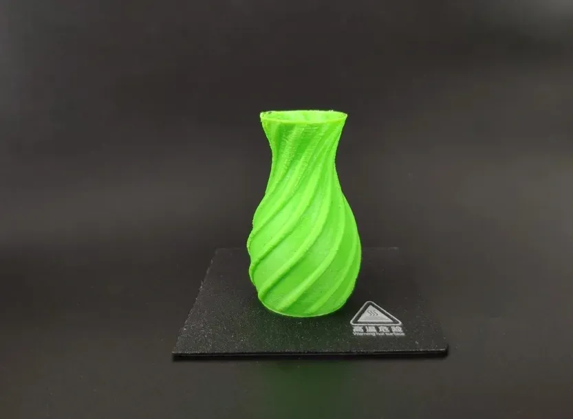
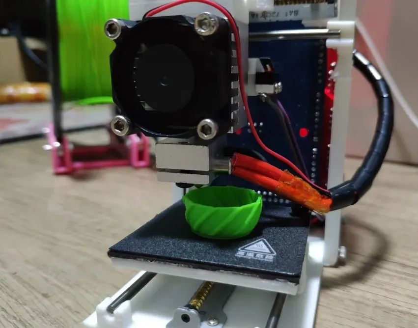
First, let's look at the printing effect
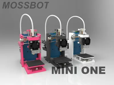
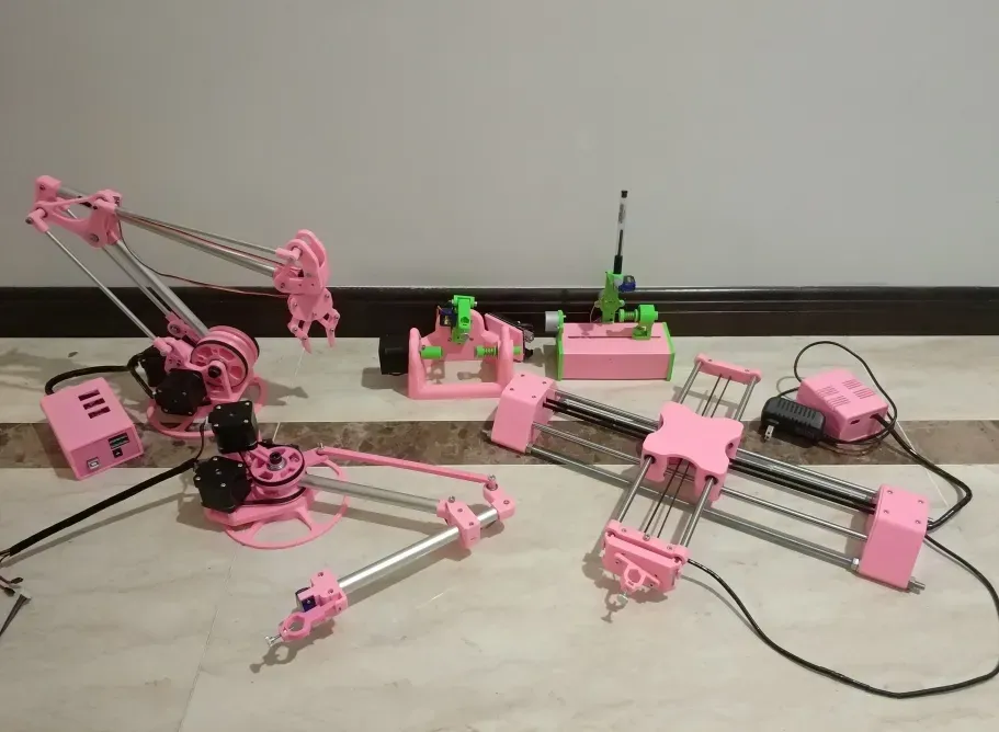
As usual, here's a family photo, and I will continue to update other projects
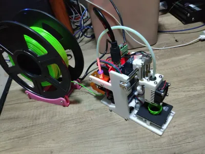
The mini one in action, it's not just good-looking, being functional is what matters
The BOM list is as follows, with a purchase link provided here: https://item.taobao.com/item.htm?ft=t&id=867635149063&spm=a21dvs.23580594.0.0.621e2c1byjDWjg

Installation Tutorial
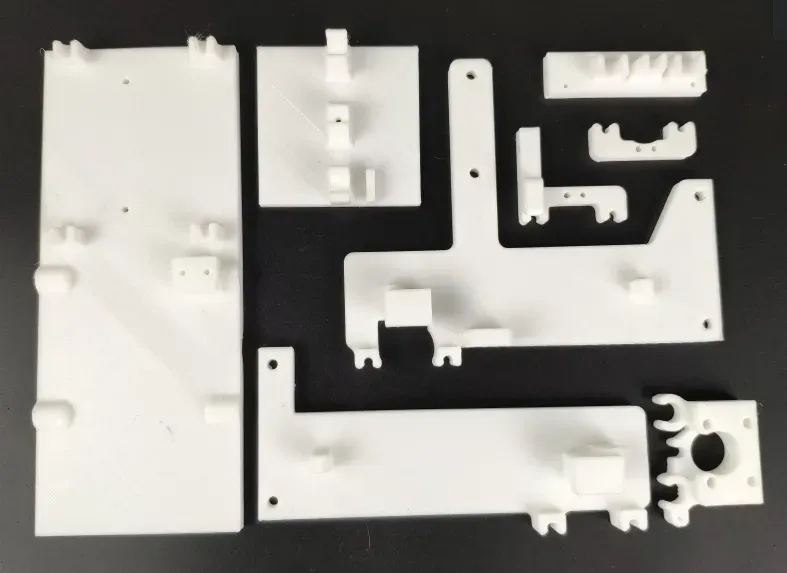
There are 8 printed parts in total
Electrical parts: MEGA2560 main control board, RAMPS 1.4 expansion board, extruder, lead screw motor, fan, A4988 stepper motor driver module, and other equipment
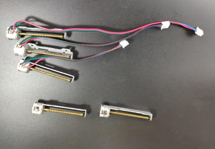
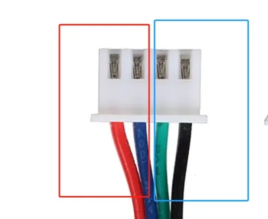
Solder the 4-pin wires to the corresponding pins of the lead screw motor. For neat wiring, the wire lengths should be 19mm for the X motor, 14mm for the Y motor, and 24mm for the Z motor. Use as little solder as possible when welding. It's best to test with a meter after soldering. The lead screw motor is a two-phase, four-wire stepper motor with four pins. Note that different motors have different wire sequences; you need to use a multimeter to test. One set that shows continuity is a phase, and the two wires of the same phase should be soldered on the same side
In the schematic below, red and blue form one phase, and green and black form another
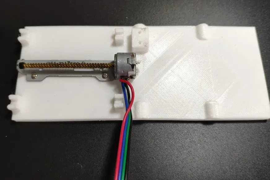
The Y-axis lead screw motor is secured with M2*6 pointed screws
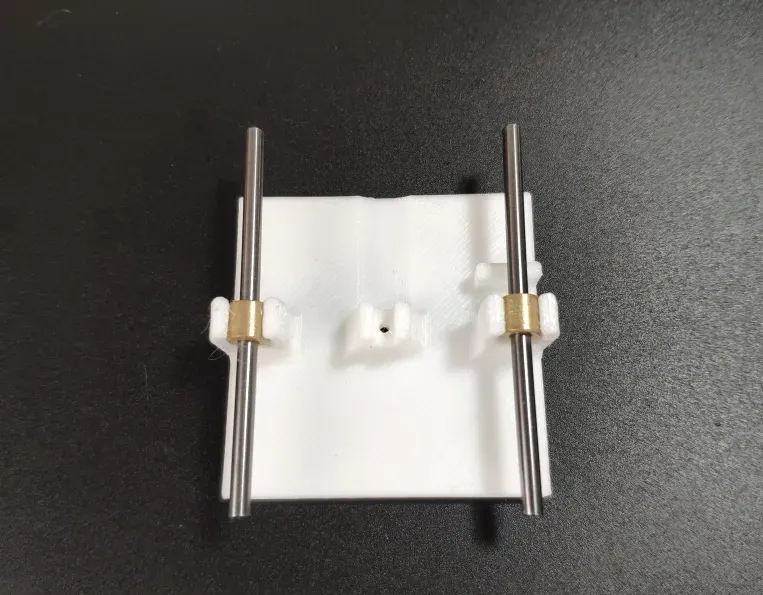
Install the copper bushing and optical axis onto the slider. The copper bushing should be inserted horizontally from the side first; do not press it vertically directly into the clip to avoid breakage
Attach the slider to the base, paying attention to the correct orientation and the direction of the stopper in the image
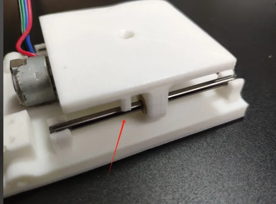
The M2*6 pointed screw here acts as the transmission mechanism between the slider and the lead screw motor. The tightening depth needs to be controlled so that the lead screw is neither too tight nor has significant play
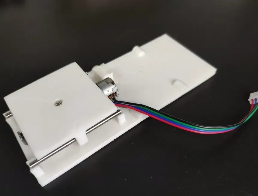
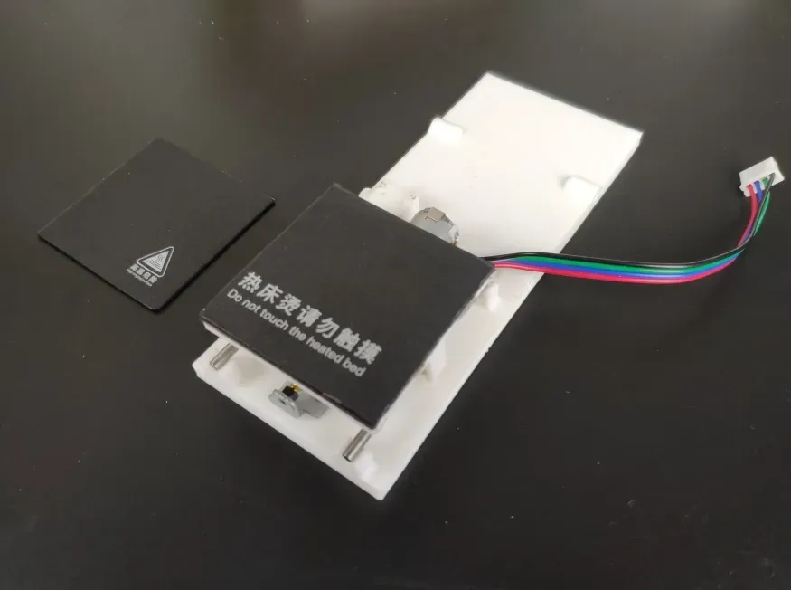
Apply the film. The large piece I bought was cut with text on it, and the effect is perfect
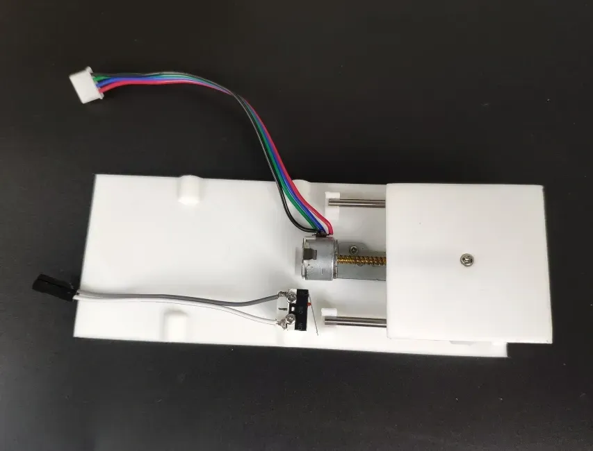
Install the Y-axis limit switch. Solder the limit switch wires to pins 1 and 3. The same applies to limit switches in other positions. Use M2*10 self-tapping screws for fixation
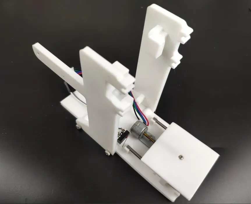
Install the left and right brackets, secured with M3*12 self-tapping screws
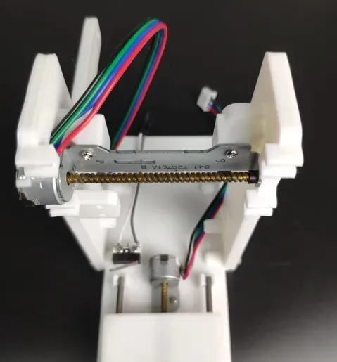
Install the X-axis lead screw motor, secured with M2*10 self-tapping screws
Install the copper bushing and optical axis on the Z-axis bracket
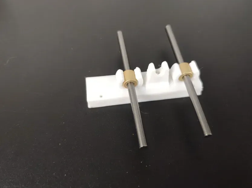
Assemble the Z-axis bracket, with the direction as shown in the figure. Use M2*10 self-tapping screws, and screw an M2*6 pointed self-tapping screw into the small hole in the middle
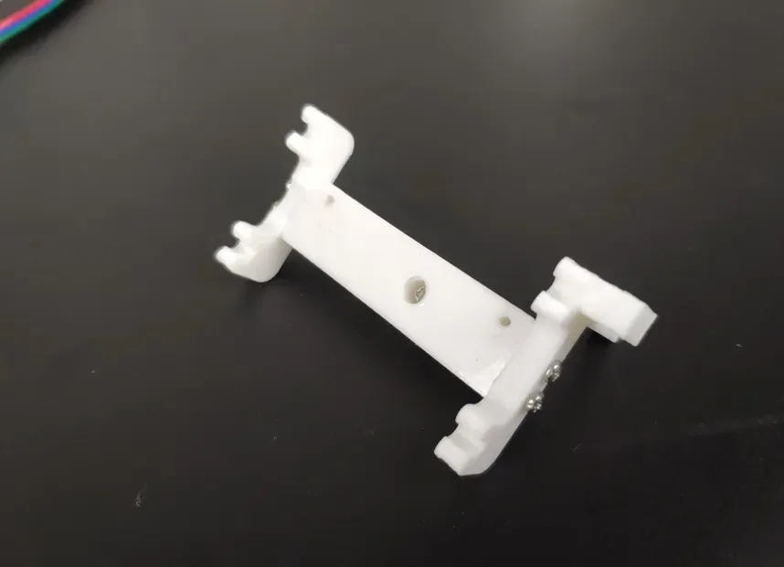
Install the previously assembled Z-axis module onto the bracket, adjusting the middle screw so it is neither too tight nor too loose
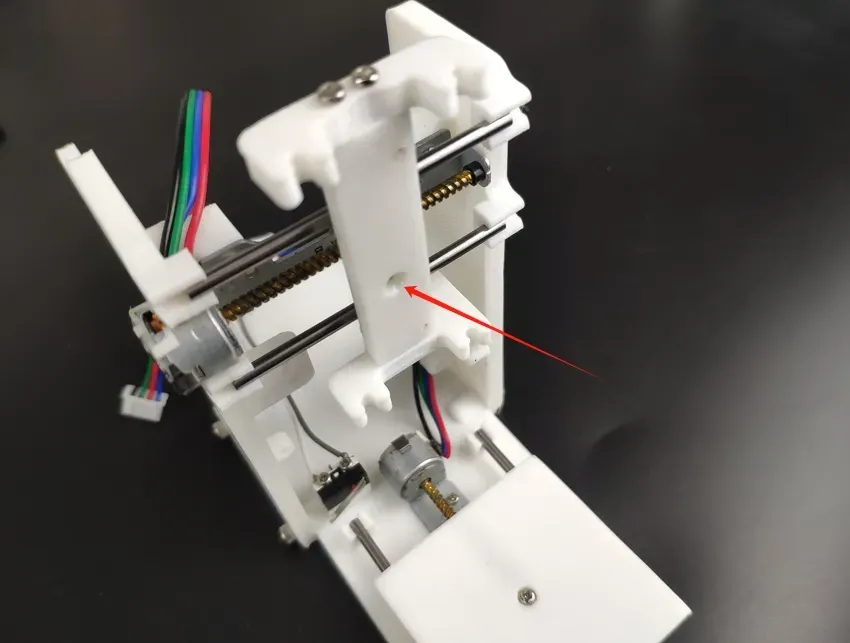
Install the Z-axis lead screw motor, secured with M2*6 self-tapping screws
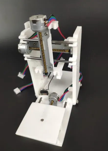
Screw the M2*16 self-tapping screw into the nozzle mount and snap on the copper bushing
Insert the optical axis, then snap on the main body. Screw an M2*6 pointed self-tapping screw into the small side hole, ensuring it's neither too tight nor too loose. Use three M3*12 screws to secure the nozzle
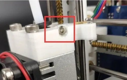
Install the X limit switch, secured with M2*10 self-tapping screws
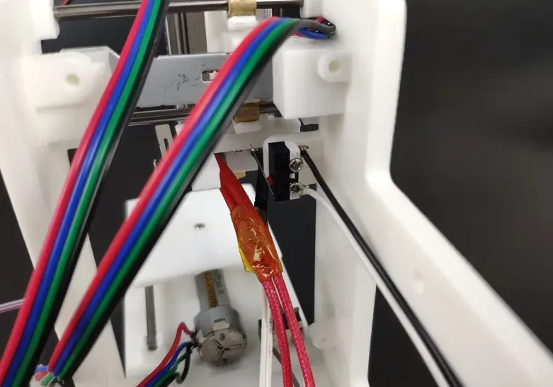
Install the Z limit switch, secured with M2*10 self-tapping screws

Install the heating rod, paying attention to the wiring
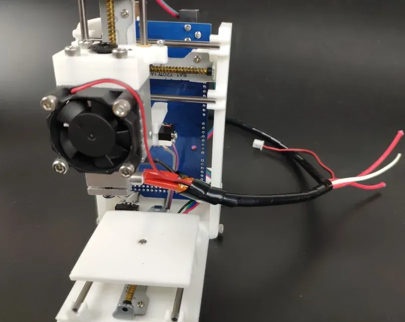
Install the MEGA2560 main control board on the back of the bracket, secured with four M3*6 self-tapping screws
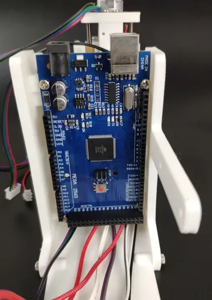
Install the expansion board and insert 12 jumper caps. The purpose is to set the subdivision mode of the A4988 driver module to 16 microsteps, meaning 1 pulse signal causes the motor to rotate 1/16 of a step angle, improving control precision. Note! E0 was missed in the photo, but it must be inserted in practice
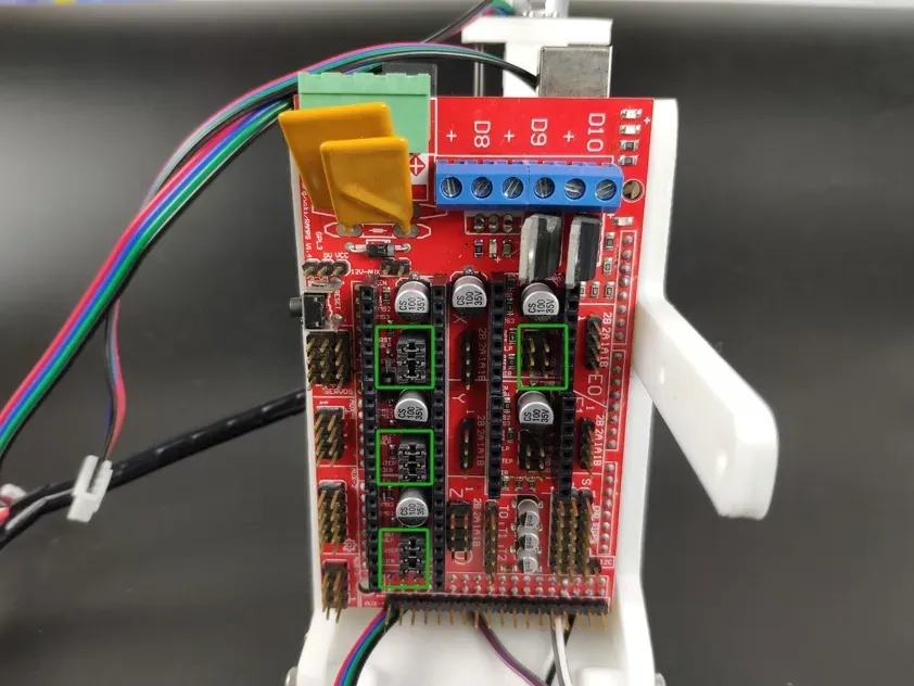
Install the A4988 stepper motor driver module, ensuring the installation direction is as shown in the picture, with the adjustment screw facing downwards
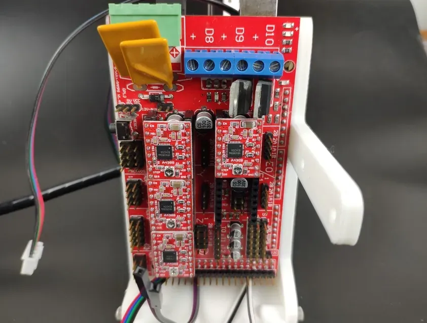
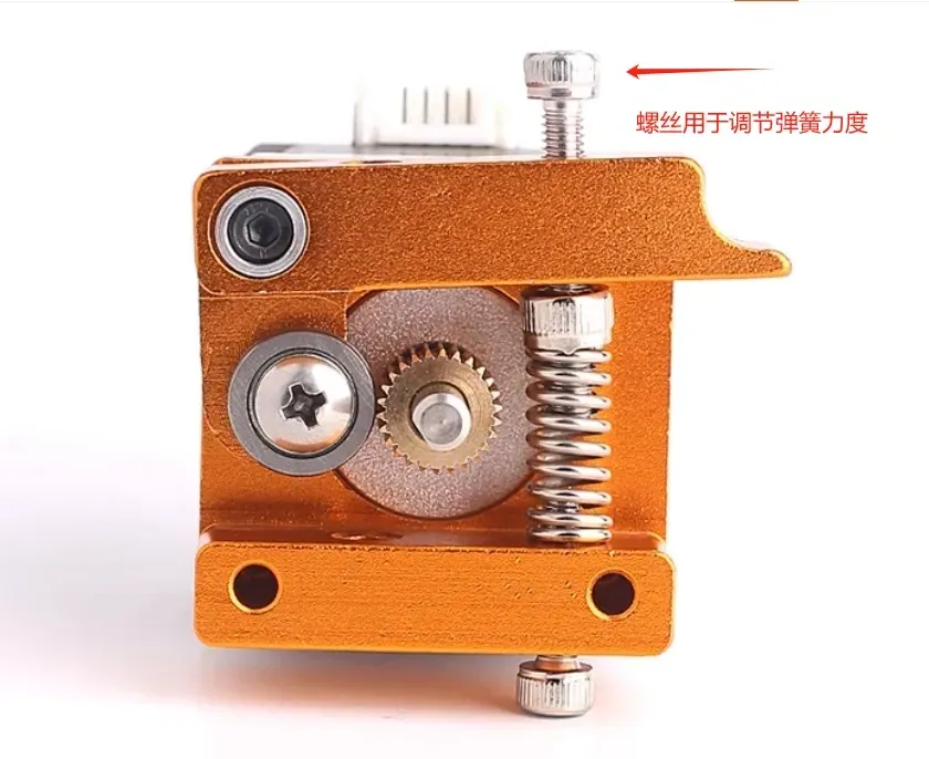
Connect the wires and install the extruder
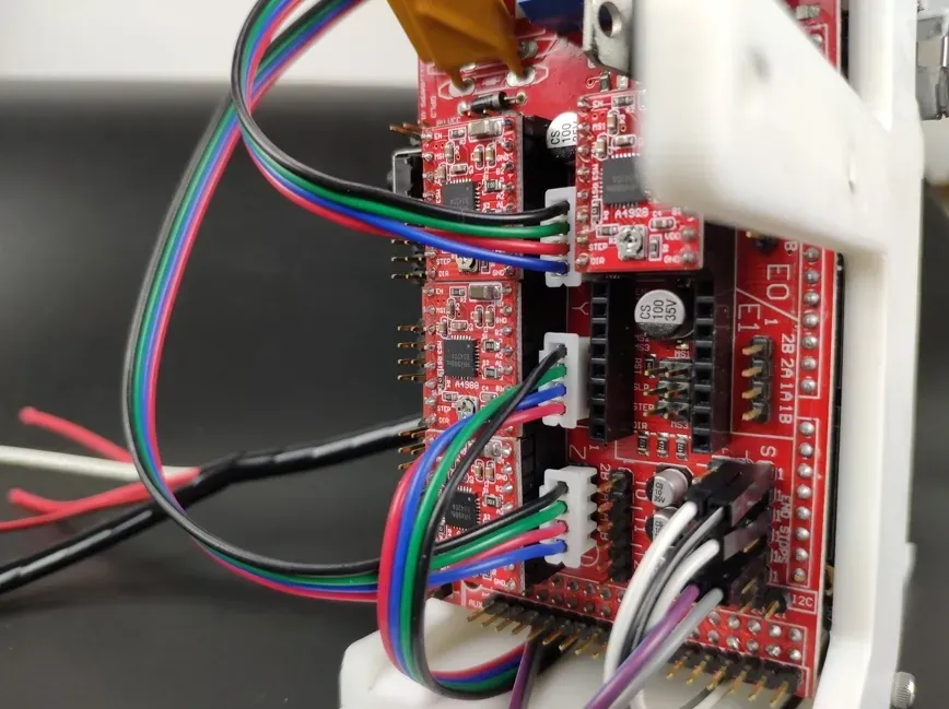
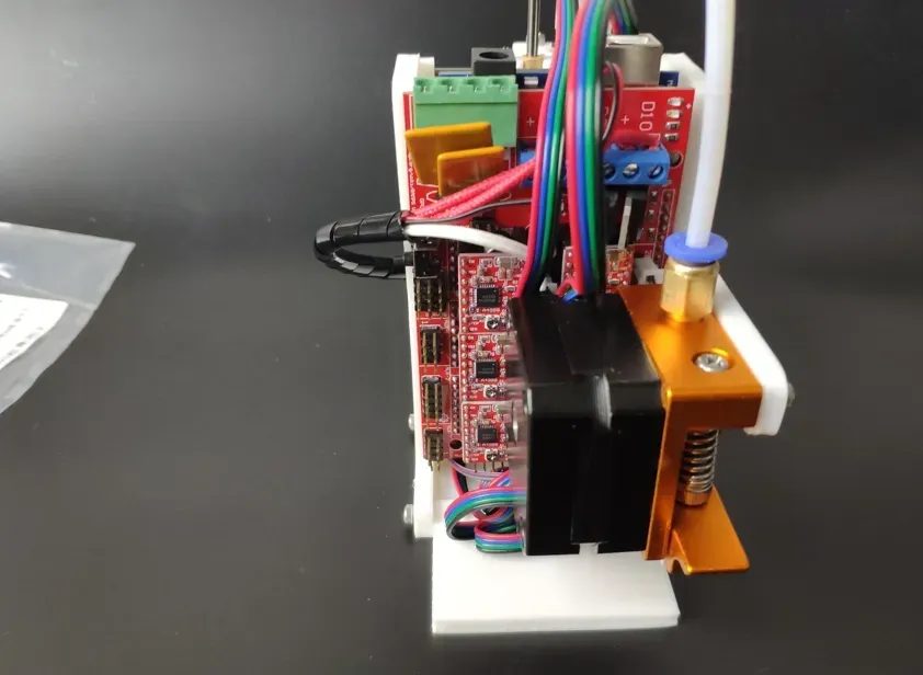
The extruder installation diagram is as follows
The wiring diagram is as follows: The XYZ motors and extruder motor should be plugged into their corresponding labeled sockets. Polarity doesn't matter initially; check the actual motor rotation direction during debugging. If the direction is opposite, simply reverse the corresponding motor wire. The heating rod plugged into D10 doesn't require distinguishing polarity. The fan connected to D9 requires distinguishing polarity (fan wires are typically red for positive, black for negative). The temperature sensor plugged into T0 does not distinguish polarity, and the limit switches plugged into 1, 3, and 5 do not distinguish polarity.
Important!!!! The power cord cannot be plugged directly into the Mega2560 main control board. The power cord must be plugged into the green connector on the RAMPS 1.4 expansion board. The green connector from top to bottom is positive, negative, positive, negative. Since there is only one power supply, you need to cut a small section of the power cord and short pins 1-3 and 2-4 of the green connector
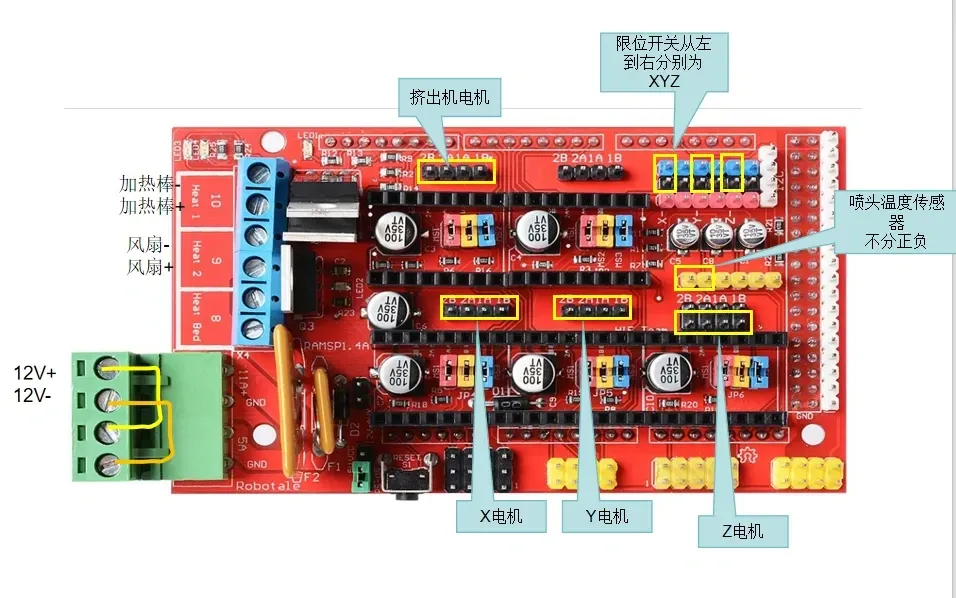
XYZ motor debugging method:
Turn the potentiometer screw on the A4988 module counterclockwise all the way down, then power it on and slowly increase the current clockwise until the motor moves strongly enough to drive the machine without overheating significantly. After adjusting my motor, the reference voltage Vref was 0.28V, which you can use as a reference.
For adjustment methods, refer to
https://bachinmaker.com/wikicn/doku.php?do=export_xhtml&id=a4988%E9%A9%B1%E5%8A%A8%E7%9A%84%E7%94%B5%E6%B5%81%E8%B0%83%E8%8A%82%E4%B8%8E%E6%B5%8B%E9%87%8F
Software Debugging
After completing the hardware section, start uploading the firmware. For instructions on how to upload firmware, refer to the Arduino basic tutorial post.
Firmware download: https://github.com/mossbot-MG/mini-one-pocket-3D-printer-firmware
Other data packages to be used are as follows:
https://pan.baidu.com/s/1uD-1DVJ6nPQ4FFtsU3a3Sg?pwd=beag
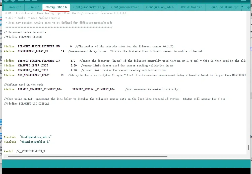
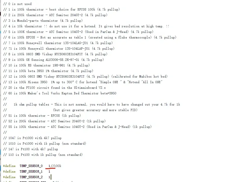
The firmware is based on Marlin 1.0.2, modified using Arduino IDE. The main parameter modifications are as follows; modify the content of configuration.h
Define the nozzle thermistor type. The common type is a 100k resistor. Our temperature sensor is plugged into the T0 position, so T0 is set to 1. If it's another type of thermistor, you can modify the value yourself according to the previous comments
Define the limit switch type. Our limit switches are set at the XYZ minimums, so only the first 3 lines need to be set. Normally closed is false, normally open is true, and the default is false
Define the XYZE movement direction. If the movement direction is inconsistent with the settings, you can modify the parameters here (true and false) or reverse the motor plug

Define the home direction. By default, the XYZ minimum direction is the home direction

Set the motor resolution. The XYZ motor step angle is 18°, with 16 microsteps. The lead screw pitch is 1.5mm, so 16*360°/18°/1.5=213.33

The maximum speed and maximum acceleration can be left at default or adjusted manually. Too slow a speed affects efficiency, while too fast a speed affects print quality and may cause motor skipped steps. If the motor skips steps during printing, simply reduce the speed and acceleration appropriately.
Set the initial acceleration. To ensure continuous motion, the actual trajectory is an arc instead of a polyline. This speed represents the minimum speed at the intersection of two trapezoidal acceleration/deceleration segments. A larger value results in a larger trajectory arc radius

Install the CH340 control board driver, selecting the installation package corresponding to your system.
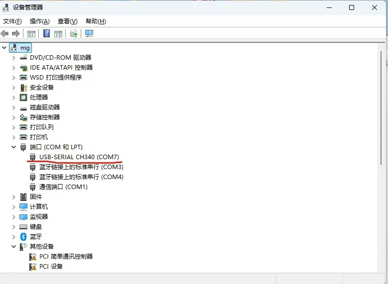
After installing the driver, plug in the printer's power cord and connect it to your computer with a USB cable. Open Device Manager, and you will see a CH340/CH341 port. Note its port number, which is COM7 in the figure
Open the firmware with Arduino IDE, and set the board, processor, port, and programmer. As shown in the figure, the port is the one displayed in the previous image. Finally, click the right arrow to upload the firmware
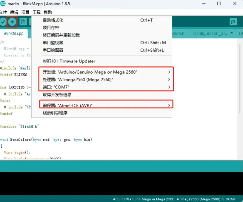
Upload successful as shown in the figure

Use Pronterface printer debugging software
Select the corresponding port, set the baud rate to 115200, then click connect. If return values appear on the right, it indicates a successful connection
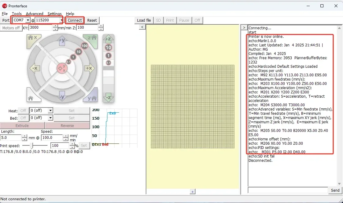
The printer can be controlled via the corresponding buttons.
If the motor does not move, check if the power cable is connected correctly. If the motor moves in the opposite direction, reverse the motor plug. 0.1, 1, and 10 represent movement distances. If the actual movement distance is inconsistent, check if all jumper caps under the driver module are shorted. You can also adjust the actual movement distance by modifying the stepper motor resolution. For lead screw motors with different pitches, the actual movement distance can also be adjusted by modifying the stepper motor resolution. If the motor only vibrates but does not move, check if the motor soldering sequence is correct. It is also possible that the driver module current is too low; increase the driver module current appropriately to increase motor torque. Motor heating will also increase, so do not adjust it too high; you can attach the driver module's heat sink to the motor. If the nozzle temperature is not displayed, check if the nozzle temperature sensor is properly plugged in. If the displayed temperature differs too much from the ambient temperature, the thermistor resistance value is set incorrectly and needs to be reconfigured. If the nozzle does not heat up, check if the hotend is connected correctly
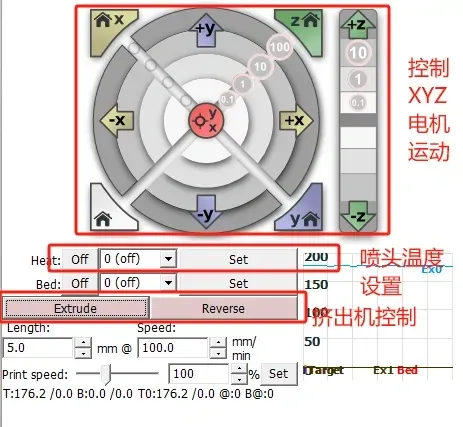
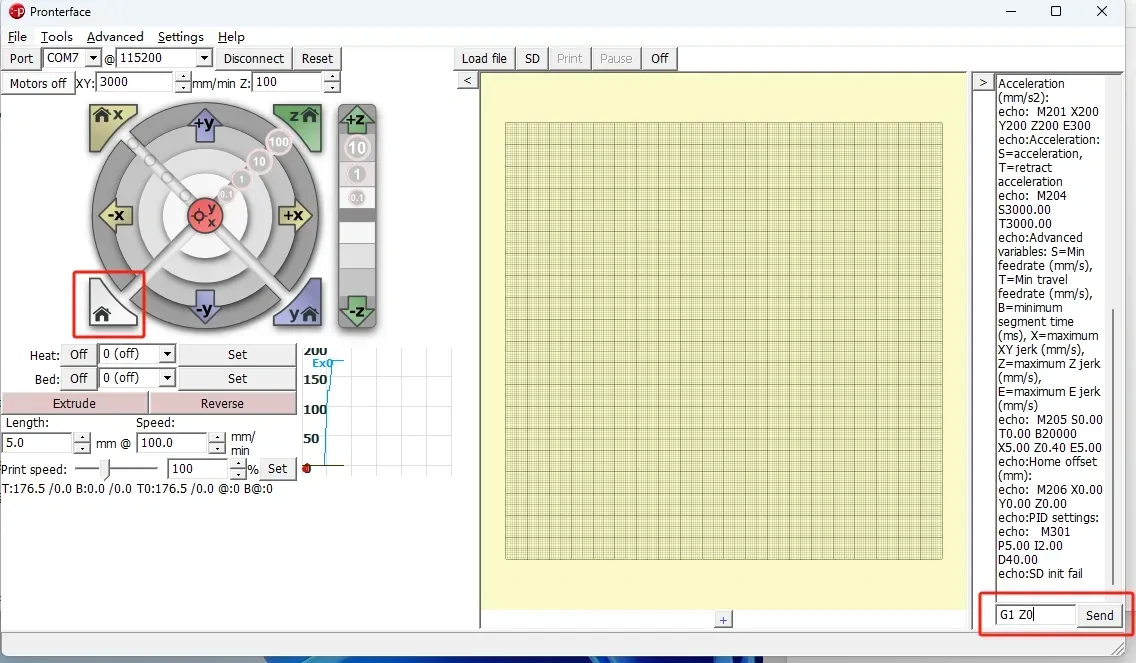
After normal function debugging, click home to return to zero. The Z-home position is at the highest point. Send G1 Z0 to move the Z-axis to position 0 and observe if the nozzle and build plate make contact. If the position is unsuitable, fine-tune the Z-axis limit switch trigger screw and repeat this step
Use common slicing software to connect the printer. Cura is recommended here as it is simple and easy to get started. You can search for specific usage tutorials online.
After connecting, set the printer parameters such as length, width, and height, then drag in the model to start printing
Disclaimer: All content is original by me, and the copyright belongs to me. If reprinting, please indicate the source
License

You shall not share, sub-license, sell, rent, host, transfer, or distribute in any way the digital or 3D printed versions of this object, nor any other derivative work of this object in its digital or physical format (including - but not limited to - remixes of this object, and hosting on other digital platforms). The objects may not be used without permission in any way whatsoever in which you charge money, or collect fees.


Comment & Rating (673)