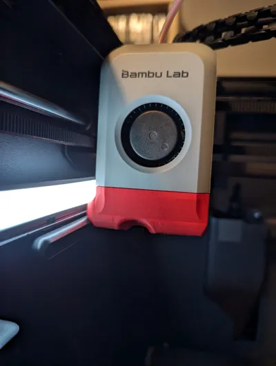
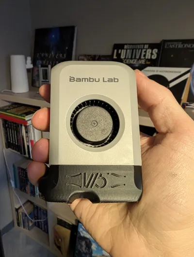
Bambulab P1S part cooling fanduct


Print Profile(3)


Bill of Materials


Description
This part cooling fanduct will provide you a 25% stronger airflow without changing the 5015 fan. It will allow you to print overhangs with a better quality at high speeds so mainly the PLA will benefit. The X1C version is not tested (I don't have one) but should provide same the performances.
Historic:
- I tested several part cooling fanducts here on makerworld but they were inferiors to the stock bambulab one when I tried them on overhang tests, so I decided to build one by myself.
- I tested 360° open ring shapes, 360° divided ring shapes, 3 outputs with 3rd on front, 3 outputs with 3rd on rear, symmetrical outputs, etc. Not better.
- This is then the 15th version of several trial and error designs that aim to improve the stock fanduct. for this one I decided to rebuild the stock bambulab P1S/X1C fanduct, that works quite well in my opinion, and restart from this point. The general shape and placement for outputs is then similar because in my experience from my failed designs, more than 2 air outputs were counterproductive each time I tried, and symmetrical outputs were worse than the asymmetrical versions all things equal.
Performances and results:
- In consequence of the similar general shape compared to the stock fanduct, it still blows air in the north west direction like the bambulab fanduct. But is there a proof that it would be better if centered ?
- The main source of airflow is the 5015 and it hasn't changed so one can not expect a dramatic increase in performance, however I managed to get a 25% increase airflow force under the nozzle, measurements and tests as a proof :
- I can now print decent 65° overhangs with a old wet wood PLA, the default P1S profile except for auxiliary fan disabled and a coolplate. I have not tried it with auxiliary fan enabled but I imagine the result will be better, and even more with a dry filament,
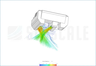
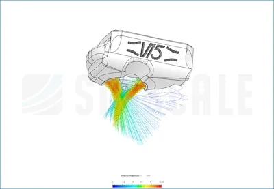
- Based on the simscale results it can be clearly seen that the new version achieves a higher velocity magnitude (same colorscale for both images) and a more concentrated airflow. The simulations were performed with surrouding boundaries at the atmospheric pressure and a fan inlet with an arbitrary volumetric flow of 0.005 m3/s at +72Pa from atmosperic pressure,
- I tested both with a glass filled of water and indeed the higher airflow is evident, the hollow is deeper with the new version,
- Both were also tested on a precision balance and the new version show a 25% greater push force (2.0g vs 2.5g),
- The speed benchy, on the P1S SD card, showed sagging overhangs with the stock fanduct, this is not the case with the new version.
Changes compared to stock fanduct:
- Bambulab fanduct is partially blowing on the solicon sock so I lowered the ouptuts by 2mm and shrinked them a bit to better target the nozzle tip. Internals are also rounded to better guide the airflow. This gives 75% of the quality improvement,
- I tried to follow a Venturi design with a 21° slope from regular section to small section, and this small section is as long as wide (4mm). This for better air speed on outputs. This gives the last 25% of the quality improvement,
- I am not totally sure it is compatible with X1C so a cutted version is also available which I am sure it works with the lidar, thanks to @Alex.Vikingo. This version is not yet tested so maybe it does not have the same performance than the uncutted version.
- NEW (2025 11 15):
- I added a shield extended until the silicon sock to prevent air to go up as I discovered thanks to a Simscale CFD simulation
- No more air leakage between the fan and the fanduct
- One of the air outlet is now extended a bit behind the nozzle to improve oberhangs on this side
Results:
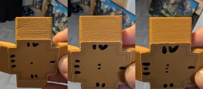
- You can see the improvements on the gifs (it blows quite harder) and pictures of 65° overhangs. I did all my PLA overhang tests with top cover removed, front door open, default P1S profile for PLA except auxiliary fan off and coolplate at 30°c .
- Better results will be obtained for higher layer times. With original fanduct and aux fan off, 4s (default layer time) are enough to pass 45° slopes, 8s to pass 60° slopes and 12.5s to pass 70-75° slopes. Not tested with aux fan on, but expect even better results in this case.
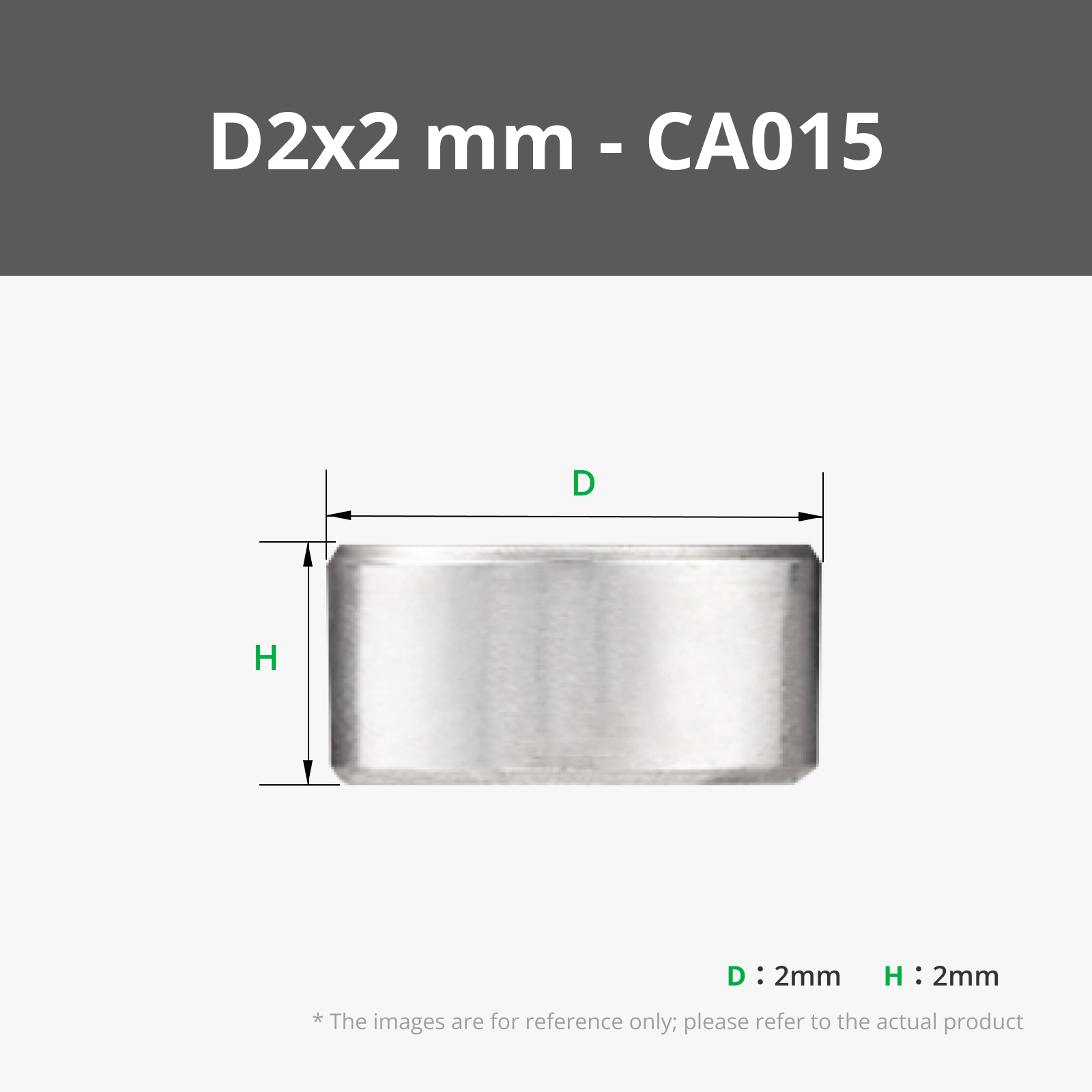
Bill of material:
- You will need the original magnets and screws. I choose to buy and sacrifice a spare toolhead cover for that so I can keep the original toolhead cover as a backup.
Profile and material:
- To print the fanduct:
- I recommend to print it with with PETG 0.08mm layer height, 2 walls and snug supports (not tree) only on build plate together with top Z distance 0.08mm. Except for testing I do not recommend to print it with PLA unless you always put off the top cover and let the front door open, otherwise the temperature will rise and deform the fanduct.
- To print parts:
- For PLA, just continue to clic on “print" as usual.
- As the fanduct is 25% more powerful than the stock one, I recommend to adjust your cooling settings for filaments that behaves better with less cooling. As an exemple for PETG HF I reduced both “Min fan speed threshold” and “Max fan speed threshold” from 20% to 16% and 40% to 32% respectively to take into account the 25% more power.
Changelog:
- Update 2024 12 17: better view on nozzle from front door
- Update 2024 12 22: lighter printed part (~12gr with above parameters). It is still a bit ~0.8g heavier than the original (see pictures) but this should not influence the Input Shaper.
- Update 2025 01 03: modified tiny external details from 0.4mm to 0.45mm thickness to not show void local layer with default P1S profile. This avoids to switch on parameters like “Detect thin walls” or “Arachne” wall generator.
- Update 2025 02 09: Update external shape to increase compatibility with X1C lidar, also 1g lighter.
- Update 2025 02 11: Added an additional version compatible with X1C.
- Update 2025 11 15 : Performance upgrade !
- Added a shield extended around the heatblock silicon sock to prevent air to partially go up as I discovered thanks to a Simscale CFD simulation. Better airflow towards the plate, confirmed by a test with the hand below the fanduct. It should also avoid hot air to go down from the heatsink fan.
- One of the air outlets is now extended backwards to be more symmetrical compared to the other air outlet. Better internal shape on this side also. This modification was intended to improve overhangs close to this air outlet because quality was bad on this side. This weakness was also observed with the CFD simulation.
Fixed an air leakage between the fan and the fanduct as I discovered by passing a thin piece of paper close to the joint. More air is then pushed through the fanduct so cooling is mechanicaly improved for both air outlets.
→Pictures with one central dot are with original Bambulab fanduct, pictures with two dots are with previous version, pictures with three dots are with the new version. There are also two gifs to compare original fanduct vs this version.
- Update 2025 11 21 : thicker shield to avoid heat creep.
Comment & Rating (70)