
Catapult for a Marble Run
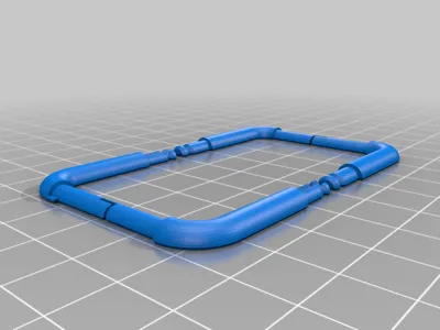
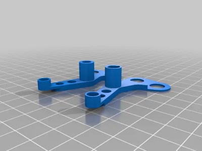
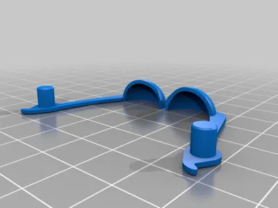
Print Profile(1)

Bill of Materials
- Screw x 2: M8x20
- Nut x 4: M8
Description
I would appreciate feedback, also to eliminate any identified problems, or if anyone has suggestions for simplification and easier printing.
English see Files
Update 04.05.2020:
- Cutout on the arm, for the sling, enlarged by 0.4mm.
- Uploaded a 0.4mm larger housing.
- Modified Arm, to get 0.4mm more clearance between Arm and Schlinge.
- Second, 0.4mm bigger "Gehäuse"
Update 14.03.2021:
- Uploaded a Catcher with a curve.
- Uploaded a Catcher with a curve.
Update 02.01.2024:
- Created base plate with simple holes for the arms. Uploaded 2 variants of the housing with a wall thickness of 0.6mm.
- Modified baseplate with round holes for the arms. Housing/Case with wall thickness 0.6mm.
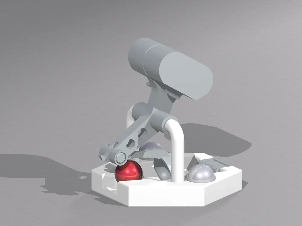

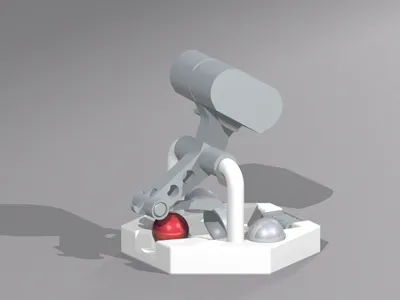
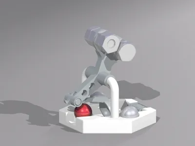
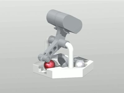
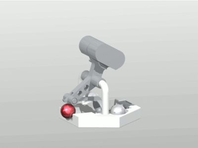
I always wanted to build a catapult based on a trebuchet, so why not for our marble run.
After initial tests, however, it was clear that to simplify the whole thing and to meet the space requirements, the movable weight is dispensed with, and a fixed arm in the form of a "scoop" is used as a sling.

The result is this catapult, which throws the ball in a fairly high arc.
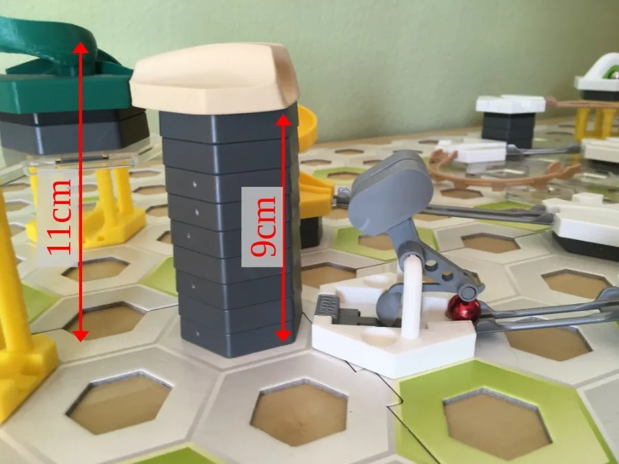
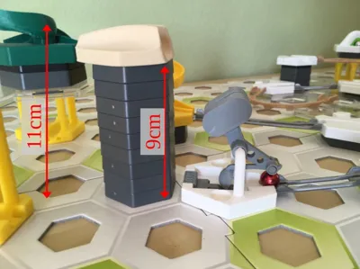
- In terms of distance, it can throw the ball over 2 fields.
- In terms of height, the ball reaches 8-9cm, with momentum it goes up to 10cm high.
Here are 3 videos showing both functions.
Here a other Video from someone else on youtube
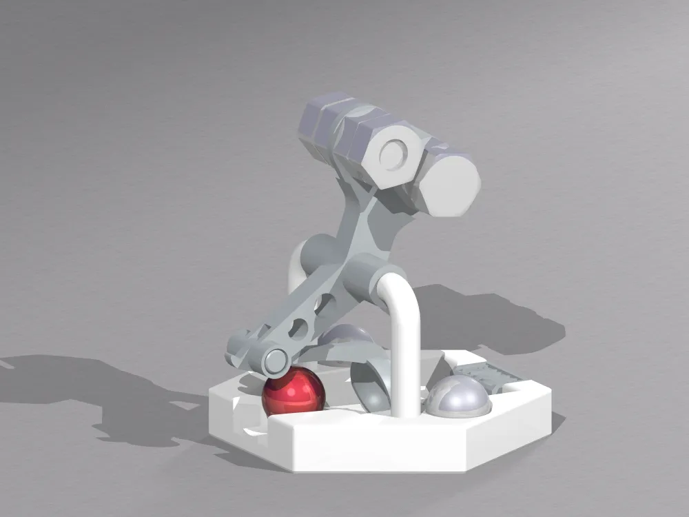
Two M8x20 screws and 6 nuts are used as weights, which also hold the
catapult arm together.
With my printer, the bores are about 0.4mm too small, and the outer dimensions are about 0.2mm too large.
Therefore, I have subtracted these tolerances from the models at the relevant points.
Recommended printing procedure:
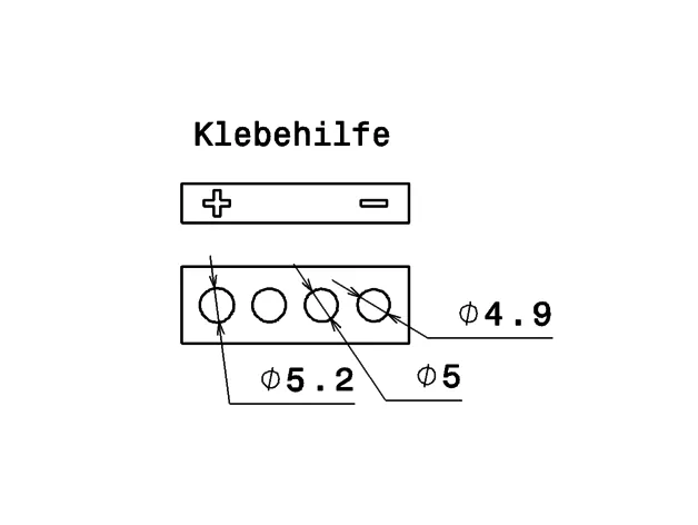
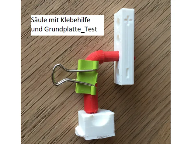
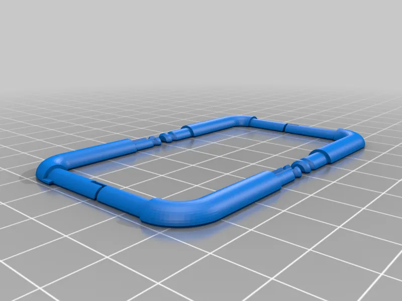
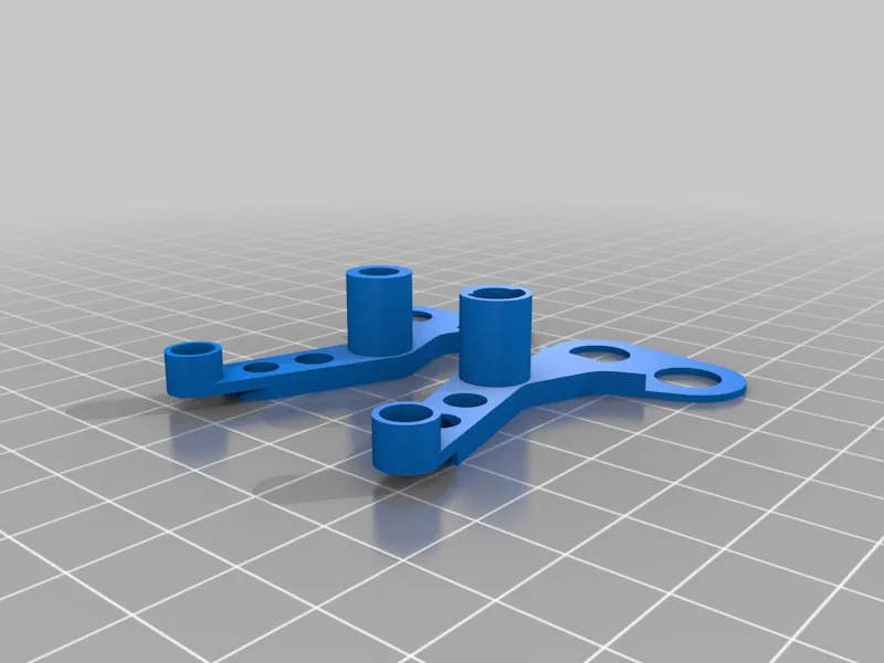
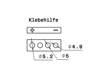
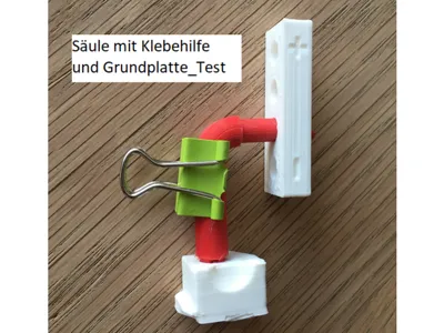
- Print the "Adhesive Aid_Column" and "Base Plate_Test". The diameters in the adhesive aid are different and should be slightly less than 5mm to slightly more than 5mm. (see drawing)
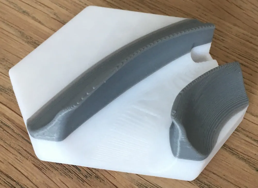
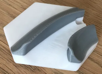
- Print the columns in 2 halves. Now the column halves can be fixed with the adhesive aid and checked with the base plate_test whether the column fits. Then glue the halves together. (see picture)
If the columns are too thick, move the columns down by -0.1mm in Z in the slicer. 3. Print the "Arm" (with support structure at the tip), the 2 halves are not glued. Check the smooth operation with the columns, otherwise grind the columns. 4. Print the "sling" (with support structure) and check the smooth operation with the arm. Then glue the "sling" together 5. Trigger, base plate and ring_catapult. The trigger must also run smoothly. 6. Housing
Assembly:
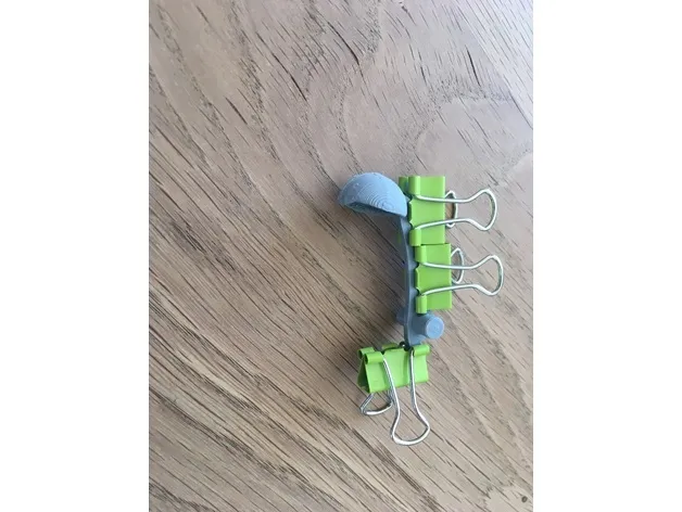
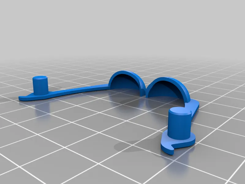
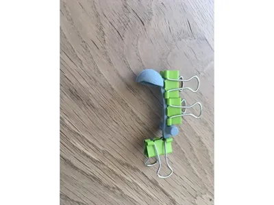
- Assemble the sling with the 2 arm halves. Turn one nut completely onto the screws. Assemble the arm with the screws and the remaining 4 nuts. (see 2nd picture)
- Insert the columns into the assembled arm and together into the base plate.
- Insert the trigger into the base plate.
- Slide the two housings onto the nuts and secure with a rubber band if necessary.
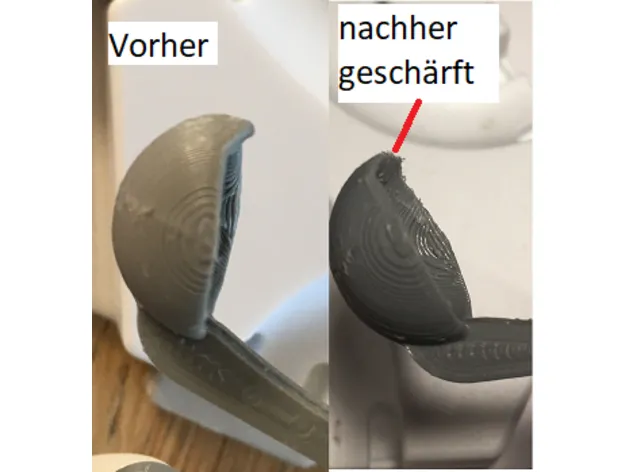
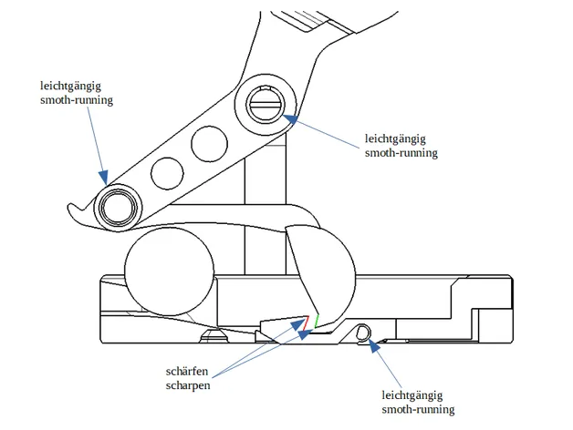
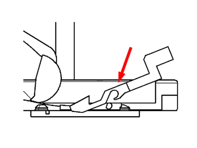
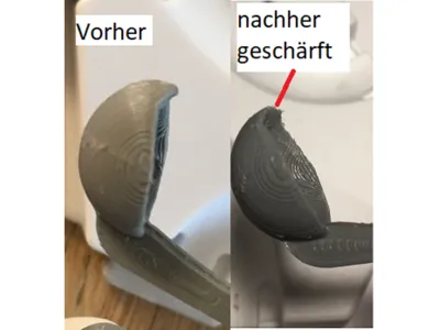
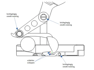
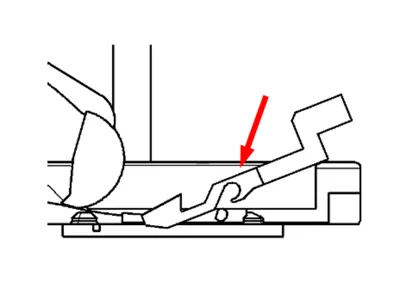
- Now comes the most difficult part. During printing, the tip of the sling and the retaining lug of the trigger are not printed "sharply" enough. Please sharpen the sling and the trigger slightly as shown in the last two pictures. The catapult must not trigger too easily and not too heavily.
The tip of the sling is also necessary to securely pick up the ball.
Print Settings
Printer Brand:
Creality
Printer:
CR-10S
Resolution:
0.2
Filament: Crality PLA
white/grey
Notes:
Nozzle 0.4mm
Category: Toys & Games
Documentation (1)
License



Comment & Rating (30)