Simple Dual Aux-Fan X1C-Mod


Print Profile(1)

Description
Boost Me (for free)
If you found this model useful, smash that boost button! I really appreciate the support!
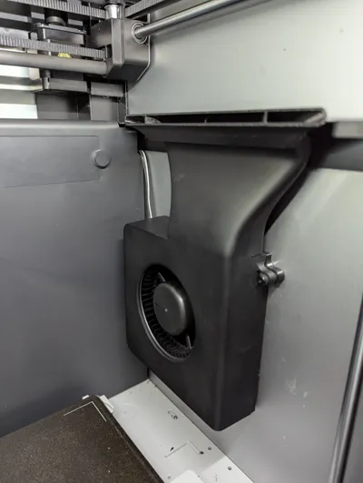
Enables you to add a secondary / dual aux fan to the right, inside your X1C!
Only requires 2 simple models to be printed:
- Fan-Backplate
- Vent-Adapter
Simple?
Well .. the design is .. I wanted to keep this dual aux fan model as simple as possible, without having to replace the entire aux fan casing like other dual fan mods. Essentially keeping it as close to plug an play as possible. I also made the vent adapter much wider so it could blow air on the entire build plate!
But why?
I needed a second aux fan solution as I print a ton of threaded parts that require serious cooling. One aux fan just wasn't enough air to cool my models…it really only cooled half of the left plate. Now the full plate is cooled! :) Maybe you might have a similair situation for your printing needs!
Sufficient Clearence?
YES… the X1 LIDAR will have just enough clearence to NOT HIT the printed fan adapter vent.
Recommended Filament:
PETG or ABS. Due to hot air temps, DO NOT USE PLA!
Required Parts:
- Auxiliary Part Cooling Fan Kit (from Bambu Store)
- Micro JST MX 1.25 4 Pin Connectors (from Amazon)
- 3 Inch Velco Circle (from Amazon - for easy aux fan removal or repairs)
Other recommendations:
- Hot Glue Gun
- Wire Stripper
- Electrical Tape
- Solder Iron / Solder
Assembly / Installation Guide:
Take the printed backplate and stick on the fuzzy circle velcro on the back, then you can velcro on the other circle but keep the sticker adehisive protector still on for now:

On the back of your second Auxilary fan, unscrew the top right screw holding the fan in and also remove the pre-installed tape:

..then partly re-screw that fan screw you just took out back into the upper right fan plate model hole:

In the box your aux fan came in, take out the 3 labeled “For X1” screws. We need these to screw in and secure the backplate model to the back of the aux fan.
Before we screw the backplate on, make sure you fold over the aux fan wiring so it runs across the back of the aux fan and out the side hole. Once the wiring is lined up, screw in all 3 X1 fan screws into the printed back fan plate. Make sure you also screw in fully the upper right fan screw through the back plate.
Now for the really annoying part of this guide…
We need to take off the back panel of the printer so we can supply the fan with power.
Follow Bambus Guide Here For Back Panel Removal ~~ ONLY FOLLOW UP TO STEP 3!!
Once the back panel has been removed you will need to unplug the existing aux fan shown on step 3 of bambu's guide.
IMPORTANT!! PLEASE REMEMBER TO TRACK EACH SCREW. There are metal to metal screws and metal to plastic screws.
In case you may have mixed things up on accident, heres a back X1C panel screw reference chart:

M= Metal Screws (thin threads)
ML= Longer - for the extruder part
PS= Metal to Plastic Small (screw like threads)
PL= Metal to Plastic Long (screw like threads)
Once the back panel is off, to make things easier, I would also remove the POOP choot. This is held in place with 2 small allen screws on the top and either 1 or 2 screws from the back panel side:


Now you need to CREATE a 3 way Micro JST Splitter as shown here:

Simply take 3 mirco jst connectors and securely connect the 4 wires to each matching color. ( electrical tape, solder, heat tape, etc)
Hot glue on 2 female adapters (these come with your jst wires) for the left and right aux fans. The main male connector of this splitter will connect back into the board.
UPDATE ON JST CONNECTORS:
Maybe the male to female JST connectors included in the JST wire pack I bought are not high quality, but it seems they were not providing a solid connection…I was having intermitent fan issues / no spinning. I ended up connecting the wires on the left and right of my splitter directly to the aux fan wires. This solved my fan issues. Just wanted to let you know if you came across any similair issues.
STOP! Before proceeding, test the splitter. Connect the splitter to the board and the 2 fans. Power on the printer and test to make sure both fans run!
Everything working? GOOD! PROCEED!
Now feed the second aux fan through the printer here:

And then, pull it out here, and run it along the wire harness clip in the rectangle below:

Here is the final wiring diagram once finished:

1 - connects to main board power, 2 - splits off to the 2nd aux fan we are installing, 3 - splits off to the stock aux fan.
I also lightly hot glued these just to make sure they stayed on securely.
Before we attach the back panel, Lets ALIGN and then STICK ON second new aux fan.
On the very top vent of your AUX fan there are 2 small screws. Remove them.
Now remove the adehsive circle on the printed fan plate cover, and then align screw holes with the holes in your X1C frame. Do this WITHOUT the the printed fan vent adapter part connected.
Align these frame holes with the aux fan top screw holes underneath:

Once its perfectly aligned, (you can see the holes through the metal frame) THEN press the aux fan back with the velcro sticky to the side of your X1C.
Now we can screw in and secure the top vent and the printed fan vent adapter.
You will NEED the 2 long screws labeled “For P1P” that came in you aux fan kit. See below:

Use these longer P1P screws to connect the printed aux fan adapter.

Test and make sure everything works.
If so, reinstall poop choote and the back cover.
You're done!
License
You shall not share, sub-license, sell, rent, host, transfer, or distribute in any way the digital or 3D printed versions of this object, nor any other derivative work of this object in its digital or physical format (including - but not limited to - remixes of this object, and hosting on other digital platforms). The objects may not be used without permission in any way whatsoever in which you charge money, or collect fees.
Comment & Rating (12)