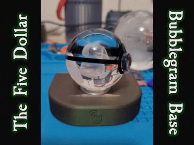
The Five Dollar Bubblegram Base


Print Profile(1)

Description
Some of my kids got some little Pokemon bubblegram balls at a con this weekend, but the vendors didn't have any bases for them. Well, I've got a soldering iron and a box full of bits, so I made some!
Features include a hidden capacitive touch sensor, WLED functionality, and only 12 total solder points! While running at full power with an RGBNW SK6812 pixel I recorded no greater than 0.5W (0.1A @ 5V) consumption, so any old phone charger should do to run this.
I've got a myriad of sizes available, supporting sphere diameters from 40-100mm in 10mm steps (and also 2-4" in ½" steps). Measure your sphere and pick the closest size.
This project uses a couple of things:
- a D1 Mini v3 (<$2)
- a TTP223 touch sensor (<$1)
- an SK6812 pixel ($0.15)
You could also use a WS2812B pixel, I just like having a white LED - two M2.3x5 screws (<$0.01)
- Two pieces 3-4" length three pin wire (~$0.08)
- about $0.90 worth of PLA (any colors you want, but you will need clear/natural!)
- soldering supplies
- a dab of hotmelt glue
- an old phone charger and Micro USB cable from the junk drawer
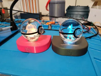
I like using black for the base, silk silver for the receiver, and whatever color is desired for the shell. This is a thin print so materials that are known for passing light might show! Mattes, additive filaments (sparkles, polychromatics, woodfill, etc), and darker colors do not have this problem. You will need something very transparent for the diffuser. I've used both natural and glow-in-the-dark PLAs (pictured). You can also simply not print the diffuser if you wish.

Comparing eSun PLA+ Magenta with Prusament Mystic Green PLA.
SETTING UP WLED
Programming your D1 is easy. Follow the instructions here, then if you wish to follow my diagram you can use my .json files attached. These will use one tap for on/off, two taps to change modes, and a press and hold to ramp brightness up and down. If you use my cfg file, you might need to use the recovery SSID to reconnect to the device to your home network. It should be broadcasting “wled-bubblegram” for you to connect to and the password is wled1234.
ON TO THE PRINT!
Start off by pushing the supports out of the shell and cleaning up any stuck bits. I used a spudger stick to help scrape them out. Different materials have had different results with how stuck they were; none were difficult to remove though.

Smear some thick gel CA glue (or better yet, some E6000) around the dent in the shell, then line up your receiver (hide the seam in the back) and wiggle it around to spread the glue around. Clamp it down.

You could also just put the sphere on it. Something to hold it down to get a solid contact for the adhesive.
While that sets, let's get to soldering! Here's the wiring diagram:

- The SK6812 pixel connects it's VCC to the D1's 5V pin and it's data pin will go to D7 / GPIO 13.
- The TTP223 will connect it's VCC to the D1's 3V3 pin and it's I/O pin to the D1's D8 / GPIO 15.
- I used a scrap of white wire to connect to the D1's GND pin, then soldered all three loose ends together.
- Use caution as you'll have the same color wires for both 3.3v and 5v uses!
It should look like this when you're done.

IMPORTANT FITMENT NOTES:
- The wires for the pixel need to come from the outside in and should not extend past the contact pads. If they do, it will not fit later. Please reference the picture!
- You'll want to use your flush cutters to knock the wires very close to the PCB on the touch sensor, as this will be pressed up against the shell when installed. Which way you solder it on shouldn't matter, but I chose to put the “TOUCH” side out, with the wires coming in from the other side.
Your pixel needs to be snapped in to the caddy. Line it up and gently press it in to place. It should be a flush fit, if not make sure you have it properly oriented and try again. There is no directionality to the caddy other than “up.”
Please ignore the wire colors in these next three images. I had VCC and GND wires reversed because I wasn't paying attention 😅

Line the caddy up in the base, then slide it in to place. It should be a nice, snug fit and does not require adhesive.


From here, fire up your hot glue gun and screw the D1 in using the M2.3x5's. Put a good glob of hot glue on the vertical part at the front of the base and hold the touch sensor in place while it cools. Pinch it down pretty good to make sure it's as flush as possible - it should not protrude past the little lip on the print!

And that's the hard part!
Tuck the wires down, line up the dovetails on the base with the slots on the shell, and slide it together. Watch to make sure you do not accidentally push the base up in to the shell. Once it's properly seated it should be plenty strong. There is a little notch on the top of the base that kinda clicks in to the shell (although it's not a super-strong lock). If you wanted, you could put some dabs of CA glue along these paths, but I haven't found it necessary as it all locks together well enough.
Documentation (2)
License
You shall not share, sub-license, sell, rent, host, transfer, or distribute in any way the digital or 3D printed versions of this object, nor any other derivative work of this object in its digital or physical format (including - but not limited to - remixes of this object, and hosting on other digital platforms). The objects may not be used without permission in any way whatsoever in which you charge money, or collect fees.
Comment & Rating (0)