Motor speed controller housing with USB-C and DC


Print Profile(2)


Bill of Materials


- 1203BB Motor Speed Controller x 1:
- DC Jack Female Connector x 1:
- PD/QC/AFC Fast Charge Decoy Trigger x 1:
Description
Motor Speed Controller Housing
USB-C and DC power input support with power output cutout.
Overview
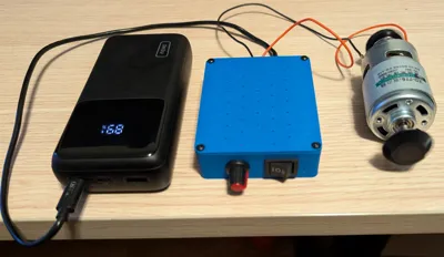
I created this housing because I wanted a way to supply variable power to various devices and personal projects.
Depending on the use-case, I have access to USB-C or DC power, so I decided to include both in this housing for simplicity.
Do not use both power inputs at the same time.
The USB-C decoy trigger has adjustable voltage conversion as well, so it can be used for 5-20V in multiple increments.
Boost Me (for free)
If you like this design, consider boosting it to show support and increase visibility :)
Bill of materials
- M3 screws
- 5x M3x5
- 4x M3x8 (up to 12mm should work too)
- 1203BB Motor speed controller
- Amazon: https://a.co/d/5R902hZ
- AliExpress: https://www.aliexpress.com/item/4001095040442.html
- DC Jack female connector
- Amazon: https://a.co/d/eYdlkJV
- AliExpress: https://www.aliexpress.com/item/4001111253454.html
- PD/QC/AFC Fast Charge Decoy Trigger
- Amazon: https://a.co/d/3SqyUP8
- AliExpress: https://www.aliexpress.com/item/1005007598243611.html
Assembly
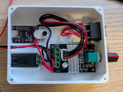
Assemble the electronics as shown in the picture below.
The right-most 2 wires are the output wires, use an appropriate length for your usage.

- Insert the switch connector through the front square hole and press-fit the switch in place.
- Put the 1203BB board in the housing by inserting the rotating part in the front round hole and align the mounting holes.
You may have extra board segments attached, you can break them apart at the seam line so that it fits properly.
Screw in the board to the housing using 4x M3x5.
Attach the switch cable to the 1203BB board.
- Push the DC female jack in the rear round hole and make sure it's snug.
- Push the USB-C decoy trigger in the rear wide hole and make sure it's snug.
Secure it in place using the printed fastener part and a M3X5 screw.
- Push the output wires from the 1203BB board through the small rear hole.
- Put the lid on the housing and align the holes.
Secure it in place using 4x M3x8 screws (anything between 6-12mm should be fine).
Enjoy :)
Printing Instructions
The only important settings for this model are:
- Seam Position: Back (business in the front, party in the back)
- Support: Normal Snug (you want supports for the front and back holes, snug gives the nicest finish and snaps out easily).
The included 3MF file includes these settings along with a few personal preferences.
I have printed this with PLA, PETG-HF, ASA and PC without issues - use whatever makes sense for your use-case.
If using ASA, PC or any other warping filament, consider using a brim to keep it on the plate (and/or liquid glue)
I've also printed it with 0.4mm and 0.6mm nozzles without issues.
For maximum quality, use shorter layer lines and slow things down, but the default profiles do a pretty great job.
Comment & Rating (16)