Mystery Clock


Print Profile(1)

Description
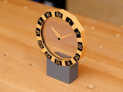
This clock is inspired by the “Mystery Clocks” produced by Louis Cartier in the early 1900s. The hands appear to move by themselves without any visible driving mechanism. In the Cartier clocks, the hands were embedded in discs of crystal that were driven at their edges by hidden gears. This humble 3D-printed version utilizes acrylic discs instead.
Another important inspiration for this clock is the amazing series of “Hollow Clocks” designed by Shiura. I borrowed the drive gears from Hollow Clock 4 and revised the gear support design in order to decrease looseness in the turning axles. The electronics were borrowed from Hollow Clock V.
Update December 2024: I designed an optional improved electronics board for the clock that has significantly greater timekeeping accuracy and causes no humming noise when the motor turns the clock hands. See end of these instructions for details.
Problems or suggestions? Please see the tips and troubleshooting section at the end of this description. Or, leave a comment below. Thanks!
Required Non-Printed Materials (All products shown or mentioned are items that I actually use and have found to work well. I have no relationship with any product supplier.)
- (2) Acrylic discs, 5 inch diameter, 2 mm (0.08") thick; source: Amazon
- Waveshare RP2040-Zero microcontroller board without pin headers
- 28BYJ-48 5V geared stepper motor with ULN2003 driver board
- USB-C 5V power supply, such as a cell phone charger
- (5) M2 self-tapping pan head screws, 6 or 8 mm length; for example: Amazon
- (3) M2 self-tapping pan head screws, 5 mm length; found in kit above
- (2) M3 self-tapping pan head screws, 4 or 5 mm length; found in kit above
- Cyanoacrylate glue (“Super” glue), medium thick; for example: Amazon
- Fine glue applicator tips — these are placed on the glue bottle’s nozzle to provide much finer control of the glue; for example: Amazon
Print files. In addition to the 3MF file, the individual STL files are also included for those with other printer brands. Some parts require non-default settings:
- Housing.stl — enable support. There is a small overhang at the housing’s bottom.
- Hands.stl — 3 wall loops, 100% rectilinear infill.
- Numeral Chips.stl — change the top 3 layers of the chips to a different color.
- Base — gyroid infill to reduce visible striations.
Assembly Step-By-Step
| Step 1a. Press/snap an acrylic disc into the drilling guide. You may need to remove part or all of the protective sheet on one side of the disc in order for it to fit. | Step 1b. Turn over the drilling guide so the acrylic disc is face down. Drill a 5/32" (4 mm) hole at the disc’s exact center. Use a drill press, if you have one. If not, an electric hand drill can be used, being mindful to hold the drill perfectly vertically. |
 |  |
| Step 2. Glue each acrylic disc into a gear ring. Apply only a very small amount of glue, using a fine glue applicator tip. Applying 1 to 2 mm at 4 points around each gear ring is enough. The glue only needs to prevent the disc from turning within the gear ring. If you apply too much glue, the drying glue’s fumes could cloud the acrylic disc. |  |
| Step 3. Using the positioning jig, glue the numerals to the front housing. Apply only a small amount of glue on each numeral so that the glue does not ooze beyond the edges. |  |
| Step 4. Test fit the gear rings, hands, and housing. Notice that the acrylic discs should face outside the gear rings. An extremely small amount of glue may be needed to hold the pins and hands in place. If too much glue is applied, the drying glue’s fumes could cloud the acrylic disc. |  |
| Step 4a. Cross sectional diagram showing the relationship between the clock hand parts. The long pin should fit loosely within the hour hand. All other pieces should fit tightly with each another. | Step 4b. There should be a 1 mm gap separating the minute hand from the front acrylic disc. A spacer is included in the print file to help achieve the correct spacing. |
 |  |
| Step 5a. Fasten the back cover with five M2x6mm (or 8 mm) screws. | Step 5b. Make sure the gear rings spin freely inside the housing. (If too loose, see tip at end.) |
 |  |
| Step 6a. Clip/trim the driver board’s 4-pin header, leaving about 2 mm of each pin. | Step 6b. Solder pads 2, 3, 4, and 5 of the controller board onto the driver board’s 4-pin header. The boards must be level in order to fit the enclosure properly. | Step 6c. Solder the controller board’s 5V and GND pads to the driver board’s (+) and (–) pads, respectively. |
 |  |  |
| Step 7a. Clip one “ear” off the stepper motor. Make an indentation with wire cutters, then bend off with pliers. | Step 7b. Place the driver board into the slot at the bottom rear of the clock base. Screw down the board with two short M3 screws. Plug in the motor. |
 |  |
| Step 8a. Assemble the gears and gear holders. Make sure the gears spin freely. Glue gear holders together (optional). | Step 8b. Place the gear assembly together with the motor onto the drive platform. | Step 8c. Press the drive platform onto the ledge inside the clock base. Run the motor wires through the cutout in the platform. |
 |  |  |
| Step 9a. Fasten the clock base’s cover with three M2x5mm screws. | Step 9b. Insert the clock housing’s tabs into the clock base. Make sure the gears in the housing and base mesh together. |
 |  |
Step 10.
Software Installation
Program Modifications — At the top of mystery-clock-uln.ino, there are constants that you can edit to change the program’s behavior.
|
Printing Tips and Troubleshooting
- Materials — I printed everything in PLA (pictured). I tried printing the base with PETG-CF, and it turned out very nicely (not shown).
- Test fitting — Before applying any glue, it is helpful to test-fit all the parts. You may find that glue is not necessary for some or all steps.
- Fit is too tight or too loose — Many parts of this model were designed for exact fit. It is possible the fit won’t be quite right when you print the various pieces, especially if you use a different printer model or different default settings. There may also be slight size variations in the non-printed materials. If this happens, try resizing the ill-fitting parts in the X and Y dimension (not Z) by 0.5 to 1.0%.
- Alternate version of clock housing — This version has a slightly different back cover that has a little less depth inside the housing. Use this version if the gear rings are too loose or rattle between the front and back surfaces inside the housing.
- Dust — While making the clock, static electricity can build up on the acrylic discs and attract dust that is impossible to wipe away. If this happens, the discs can be cleaned with a anti-static plastic or optics cleaner (for example, NOVUS) and microfiber cloth.
- If 5" acrylic discs are unavailable — Woodworkers can cut the discs from flat acrylic sheet using a router table and pattern bit. I provide a template for doing this. Use double-sided tape to stick the template to a piece of acrylic sheet that has been roughly cut to size. Be sure to use safety push blocks when routing.
Update December 2024: Improved Electronics Design on GitHub (optional)
I designed a custom electronics board that is 15 times more accurate at timekeeping than the RP2040 microcontroller alone. The custom board also eliminates the stepper motor’s audible hum when it moves. The board has 2 pushbuttons that allow fine adjustments of the hand positions.
Making the board requires soldering and basic knowledge of electronic parts. Complete instructions and board design files are available on GitHub. The updated print profile includes an alternate base that fits the custom board. |  |
Comment & Rating (15)