Lottery Wheel/Japanese Lottery Machine/ガラポン抽選器/Garapon/福引き抽選器


Print Profile(2)


Bill of Materials

Description
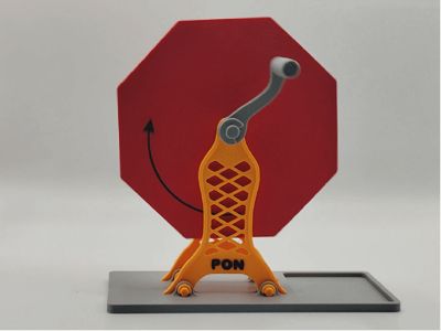
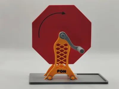
This is a model of a lottery wheel machine.
I aim to streamline the number of components required for assembly, enabling users to complete the entire model using just one 3D printer.
Due to this, I do not intend to utilize glue or screws to secure the entire chamber. Instead, I have employed the box structure of my design, expanded and contoured into an octagon.
Here are the assembly instructions accompanied by some related precautions.
Thank you for taking the time to peruse them:
On the first plate, there are three modifiers.
Below are the explanations of their functions:
Two modifiers have been incorporated into the support structure (shown in yellow in the diagram) for the shaft.

This is to create grooves for the facile removal of supports (as I utilize needle-nose pliers, the grooves facilitate gripping).
If you do not employ these two modifiers, you can also remove the supports by prying them from the gap between the support and the main body with a blade.
At the bottom, there is a hole fabricated with a cylindrical modifier, used to insert a ball after the assembly is complete.
If you do not utilize this hole, you can still insert the ball into the assembled container, but it will be comparatively more cumbersome.
(When the ball's exit is facing upwards, insert a ball, then rotate the handle counterclockwise to place the ball into the chamber.)

The hinge component of the flip cover also features a support. Remember to remove it.

After removing the supports, procure a piece of wire approximately 2 cm in length.

I excised a small fragment from a paperclip.

Employ the wire to attach the flip cover to the main structure
(pay attention to the direction of the slant on the flip cover to avoid misplacement).

Ascertain that after securing, the flip cover can freely rotate with the shaft:

Pay heed to the strength of the shaft for the cover, which has already been addressed in the box model.
The interlayer bonding strength of the Z-axis is not sufficiently robust, and there is a possibility of breakage.
Be cognizant of the force applied during installation!

The pattern on the cover is generated using a modifier, which can be customized to any design or text you desire.
This is exceedingly simple to accomplish:

Align with the direction of the slot on the hinge, and assemble them together (be mindful of the force applied):

Insert it into position, rotate to close, and the assembly of the box is complete:

Potential Issues:
There may be gaps between the panel cover and the box, as depicted in the image above.
This is due to slight deformation caused by removing it immediately after printing.
There are numerous solutions. If you do not intend to open it again, simply use glue.
However, as previously stated, I prefer not to utilize screws or glue.
Simply heat the bed, then place the assembled box panel face down on the hot bed, press with a book, and wait for the bed to cool naturally.
Of course, the optimal method is to be patient and let the bed temperature drop naturally after printing is complete.
Assembly of the Shaft:
There are also supports in the third plate (shown in yellow in the diagram).:

If you desire the circular portion of the shaft to be more rounded, you can adjust the raft layer parameters.
First, assemble the snap ring with the shaft:

Insert it into the central square aperture of the box:

Insert it to the bottom and secure it with the snap ring:

Insert the support legs into the shaft:

Attach the washer from the same plate as the handle onto the shaft, securing the support:

Secure the back support legs with a snap ring as well:

Insert the handle into the shaft:

Secure the handle with a snap ring:

The remaining steps are exceptionally straightforward:

Insert the legs of the support into the slots on the base plate, and secure them by inserting the square shaft into the hole:


You can first assemble one side of the snap ring and the shaft, and then insert it into the hole:

Install the remaining snap rings:

Other Matters:
I fabricated a matching square box to facilitate the collection of balls that fall out:

If you do not plan to utilize the plastic balls from Maker's Supply (ZB001), you can also employ this ball:

Finally, refrain from rotating too vigorously, otherwise the balls may not fall into the box.
This concludes all the assembly and instructions. Enjoy~
If you encounter any problems or have suggestions for modifications, please leave a comment. Thank you for your support.
License
You shall not share, sub-license, sell, rent, host, transfer, or distribute in any way the digital or 3D printed versions of this object, nor any other derivative work of this object in its digital or physical format (including - but not limited to - remixes of this object, and hosting on other digital platforms). The objects may not be used without permission in any way whatsoever in which you charge money, or collect fees.
Comment & Rating (19)