Nutating Disc Engine (functional demonstration)


Print Profile(1)
Description


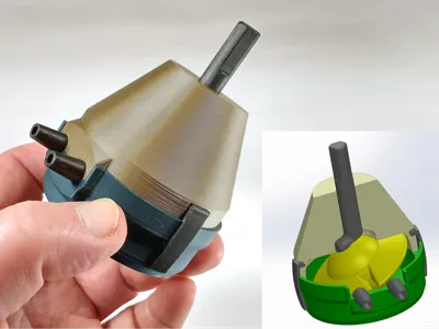
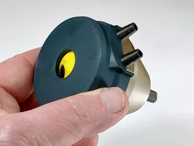
A nutating disc engine is a type of positive displacement engine that uses a wobbling disc instead of pistons or rotors. The disc inside nutates - meaning that rather than rotating, the disc wobbles on it's rim like a coin as it dies after spinning on a table. This particular model, while really just a demonstration of the concept, will actually spin if you apply enough compressed air to one of the inlet ports. Unfortunately, it lacks any proper seals which would allow it to generate any real power. On the plus side, it is very easy to disassemble to see how it works inside.

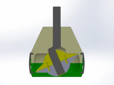
It's a little hard to figure out how this engine works until you see that 1) airflow is blocked between the inlet and the outlet by a stationary vane (that also keeps the disk from spinning) and that 2) the funky dog-leg shaft forces the conical part of the disc to seal against the top and bottom of the chamber creating isolated high pressure and low pressure air pockets. This pressure differential (from inlet to exhaust) is what causes the disc to nutate, and as it does, the inlet side alternately pressurizes above and below the disc. Note that reversing the air supply from the inlet to the outlet will reverse the engine direction.
Post-print Processing
You can demonstrate the engine by just spinning the shaft by hand, but if you want it to run with compressed air, you will need to make sure that everything runs very smoothly. The discs should spin completely freely on the short section of the axle, and the long section of the axle should spin completely freely in the top half of the housing. Note that the slot in the disc slides up and down on the vane in the housing top, so the sides of the vane should be sanded to be very smooth. Note that the 3MF file has the disc halves printed with 0.1mm layers to decrease the roughness. You could also print the housing pieces at that layer height, but I don't think it is necessary.
Assembly

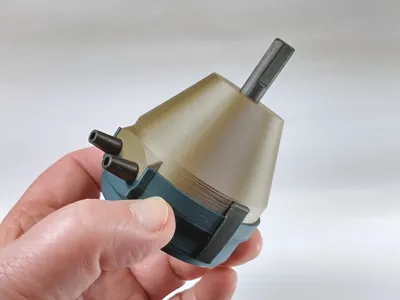
Start by inserting 4 short lengths of filament in the 4 holes in the bottom of one of the disc halves. These are alignment pins to help glue the two halves together. Put a few drops of superglue onto the surface and then place the other half on top. Make sure the slots in the two halves are perfectly aligned before the glue sets.

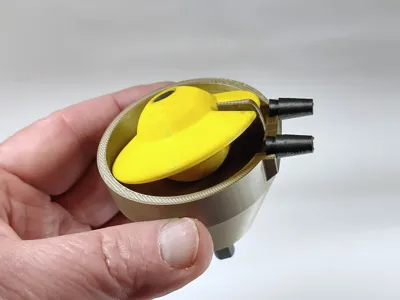
Assembling the disc onto the angled shaft and into the housing top is a little tricky in that all three pieces need to be slid together at once, and it is a little tight getting the side of the ball slid under the tip of the vane.. A little gentle flexing is sometimes required. Start the shaft into the housing and into the disc at the same time and slide everything together into the position shown above. Keep wiggling and pushing the parts together until you can slip the disc past the tip of the vane. If it seems a little too tight, you can trim a little of the tip of the vane, but trimming too much will let more air leak through the gap from input to exhaust. Test rotate the shaft - everything should feel completely smooth as the disc nutates and the slot slides up and down along the vane.
You can now slide the housing bottom into place. You can just hold the hose barbs in place as you press the housing top and bottom together, but I find it easier to superglue the hose barbs to the top half as shown above, then they won't fall out when you take the thing apart.

Lastly, press the clips into the sides of the housing to hold the top an bottom together.
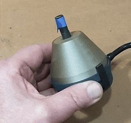
To operate, you'll need maybe 50psi and a lot of airflow to get it running, depending on how smoothly your engine operates.
Comment & Rating (2)