HexLED | LED Wall Fixture Project


Print Profile(1)

Bill of Materials

- ESP32_WROOM x 1:
- 5V_20A_PSU x 1:
- 8A_FUSE x 3:
- 1A_FUSE x 1:
- 18AWG_WIRE x 1:
- 22AWG_WIRE x 1:
Description
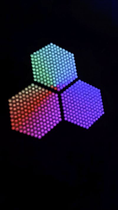
HexLED is a lighting fixture controlled via WLED. It consists of 3 hexagonal panels of individually addressable ws2812b LEDs. This is quite a big project and involves a lot of soldering.
ledmap.json file: https://pastebin.com/p9mWxhMQ
Shoutout to @_aldiy and others from the WLED discord for helping me with mapping!
Boost Me (for free)
Like this project? Feel free to leave a boost, I would greatly appreciate it!
Bill of Materials (See PDF Attachment for better formatting)
| Item | Qty | Link* |
| WS2812B LED strip, 60 LEDs/meter | 8.5 meters/507 LEDs | LOAMLIN WS2812B Strip (5M) |
| 5VDC power supply, >20A | 1 | Note: this one doesn’t include a mains cord, make sure you have one of those. I just cut the connector off of an IEC cable I had. |
| Quick blow fuses | 3x 8A fuses, 1x 1A fuse | Bojack Fuse Kit |
| ESP32 | 1 | ESP-32-WROOM |
| Wire, 24 AWG and 18 AWG recommended | ||
Optional: Wago lever connectors or wire nuts. (You can use solder too, I just used these for convenience) | 5 | |
| Optional: MAX9814 or similar microphone for sound reactive effects | 1 | MAX9814 |
*I don't get paid for any of this. I’m just linking what I used personally for this project.
Assembly (See PDF Attachment for better formatting)
I’m not going to lie, this will take a while. It took me several hours per panel, though keep in mind that I am not extremely experienced with soldering.
First of all, you will need to cut all of the LED strip to the desired length and solder pieces of wire (+, -, and data) ~5cm long to one end of each strip. Keep in mind the direction of the data line on your strip as you solder.
| LED Count | Qty |
| 8x LEDs | 6pcs |
| 9x LEDs | 6pcs |
| 10x LEDs | 6pcs |
| 11x LEDs | 6pcs |
| 12x LEDs | 6pcs |
| 13x LEDs | 6pcs |
| 14x LEDs | 6pcs |
| 15x LEDs | 3pcs |
Next, slide the pieces of pre-cut strip under the overhangs into the channels of the base. The extra wire on the end of the strip can be pushed through the wire hole at the end of each channel. This project is wired serpentine-style, so make sure that the data flow is correct.
Strip data flow
I did not have to use adhesive, however if your LEDs slide around, use the backing on the strip or hot glue.
Once all pieces of strip are in the base, you can solder all of the pieces together, connecting the wires on one piece of strip to the tinned pads of the next.
Repeat this for each panel, and test with WLED to make sure each LED lights up.
After all of the panels are wired individually, it’s time to connect them together. I have created a wiring diagram here:
Each panel connects to the same power bus. This is where I used Wago lever connectors, but you can also solder the connection. Each panel also has its own 8A inline fuse for protection. Make sure you use 18 AWG or larger for this, as it must be able to handle higher currents.
In terms of powering the ESP32, I simply connected it to the power supply with a 1A fuse just in case.
For data, you only need to connect each panel to its own GPIO on the ESP32. If you wanted to, you could run them off of 1 GPIO, but you won’t be able to apply different effects to each panel that way.
I had my ESP32 right behind the panel, but if you have a longer data run, make sure to use a sacrificial pixel or something else to avoid dropouts.
Finally, flash WLED onto your ESP32.
Under the LED preferences tab, add 3 outputs, each with a length of 169, corresponding to each GPIO you are using. The outputs should be listed in this order (when looking from the front):
Output 1: Top Panel
Output 2: Left Panel
Output 3: Right Panel
Under the 2D configuration tab, make sure to select “2D matrix.”
Head to https://pastebin.com/p9mWxhMQ, and save as ledmap.json
Navigate to ip/edit (for example, 10.0.0.2/edit) and upload the ledmap.json file.
Restart the ESP32, and try out an effect!
Before adding all of the diffusers, make sure to give everything a final test. If everything works fine, the diffusers are simply pushed into the front of the base.
After making sure everything is working properly, I used cyanoacrylate superglue to connect the parts of the trim, matching the letters on each piece of trim. Each panel should be oriented so that the data input is on the top-left corner of the fixture (when looking at it from the front. See picture on the below, arrows represent data flow)
Finally, I mounted the fixture on my wall using Command strips, as the panel does not weigh too much. That’s it, you are done!
Feel free to contact me @pupik12 on discord if you have any questions, I am happy to help!
Documentation (1)
License
You shall not share, sub-license, sell, rent, host, transfer, or distribute in any way the digital or 3D printed versions of this object, nor any other derivative work of this object in its digital or physical format (including - but not limited to - remixes of this object, and hosting on other digital platforms). The objects may not be used without permission in any way whatsoever in which you charge money, or collect fees.
Comment & Rating (12)