Search models, users, collections, and posts
Ozito PXC 20V 100W USB-PD & USB-A (QC 3.0) Charger
IP Report


Print Profile(1)

0.6mm nozzle, 0.3mm layer, 2 walls, 15% infill
Designer
1.8 h
1 plate
Open in Bambu Studio
Boost
15
44
7
2
21
8
Released
Description
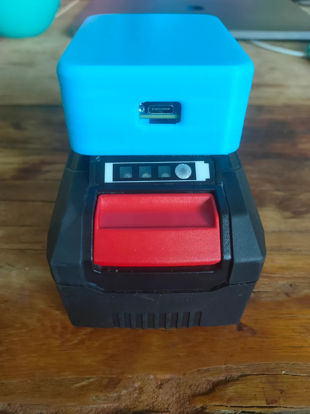
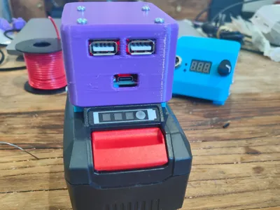
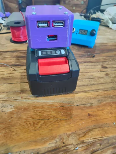
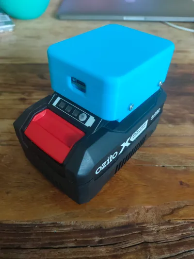
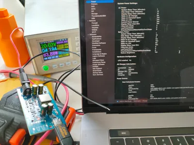
I designed this 100W USB-PD/A (QC 3.0) charging box which plugs into an Ozito 20V battery. This is ideal as it completely charges up my Macbook and other USB-PD laptops at a full 100W.
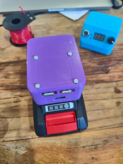
You can either print the top with USB-PD only or a dual USB-PD & USB-A (QC 3.0).
Items required:
- Ozito PXC 20V battery
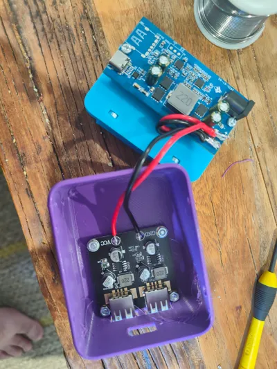
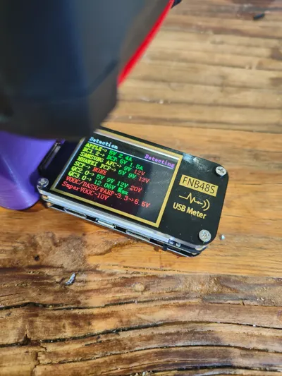
- SW2303 charging module/board (you can get this from ebay or Aliexpress). Some people have reported issues with some of these boards where it doesn't sustain 100W but I received a v1.1 and it was able to sustain a charge for an hour at 100W.
- USB-A QC charging board for USB-A charging: https://www.aliexpress.com/item/32953580059.html
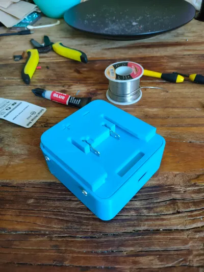
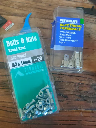
- M3x10mm nuts & bolts - I bought mine from Bunnings (https://www.bunnings.com.au/pinnacle-m3-x-10mm-zinc-plated-round-head-bolts-and-nuts-20-pack_p0247262)
- 6.3mm blade terminals - I bought the blue Narva ones from Bunnings (https://www.bunnings.com.au/narva-3mm-blue-electrical-terminal-male-blade-connector-14-pack_p4330755)
- Soldering iron
- 18AWG/7.5A wire - I bought some rolls from Jaycar (https://www.jaycar.com.au/p/WH3046)
Instructions:
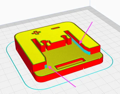
- Print all the parts. You need support as shown in the attached image.
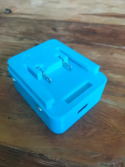
- Using a heat gun or some other heat source, heat up the blade terminals and remove the plastic insulation using pliers.
- Press the terminal connection end flat using some pliers.
- Solder some wire to the end of the terminals
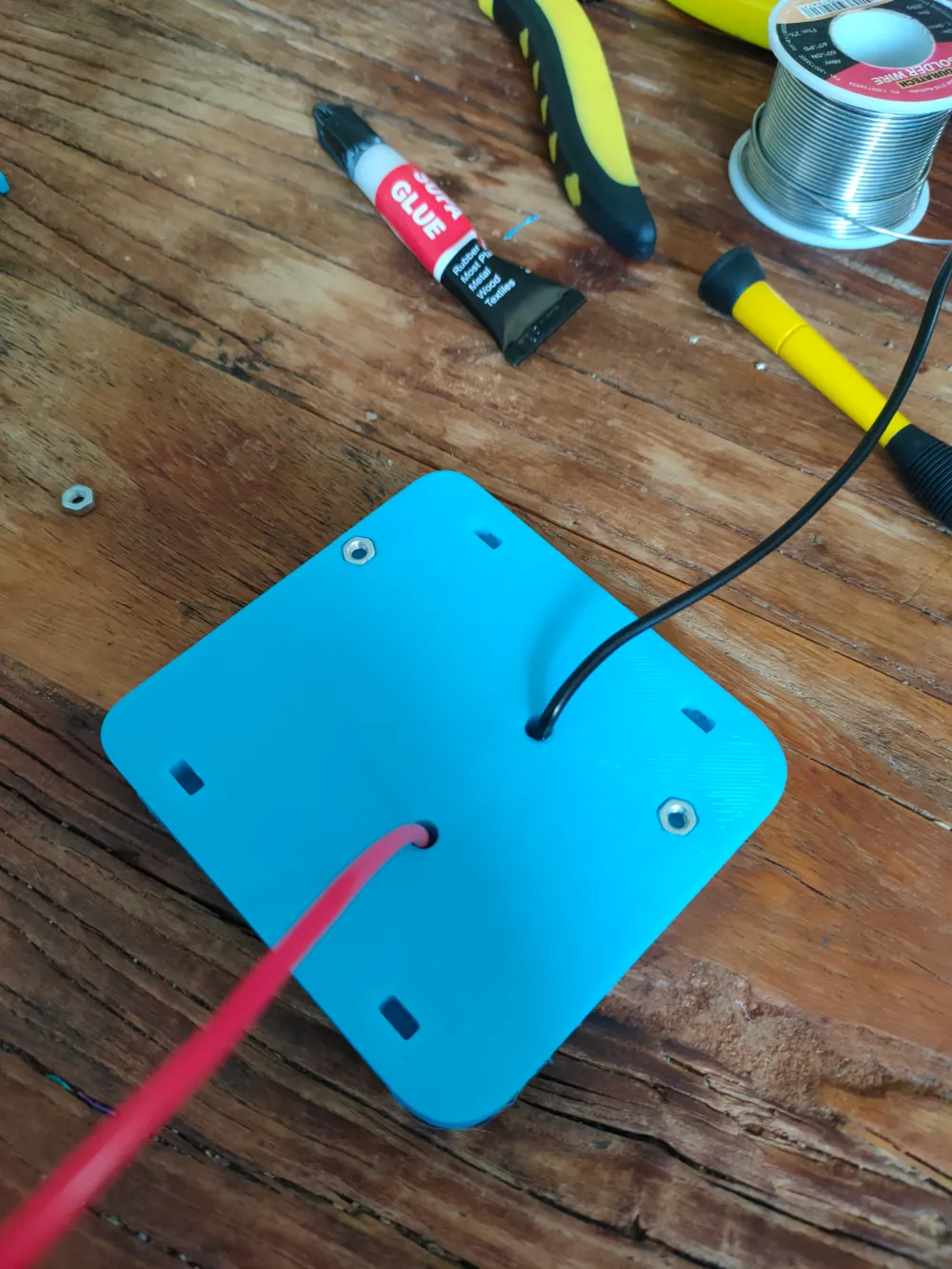
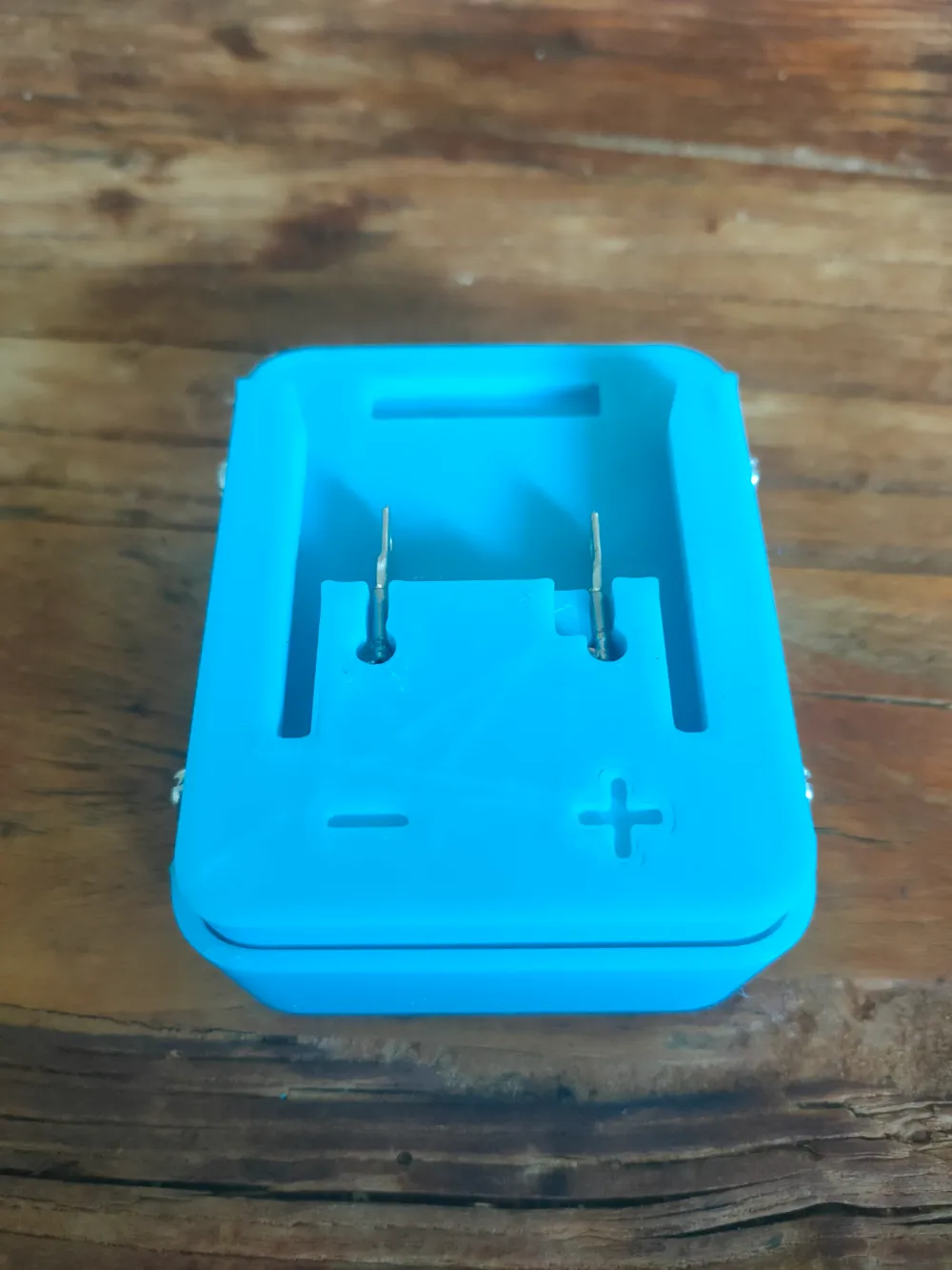
- Pull the wires through the holes in the base then press the terminals into their respective positive and negative slots. Once the terminals are aligned properly, superglue the terminals into place.
- Press the nuts into their recesses and use some superglue to fix them in there.
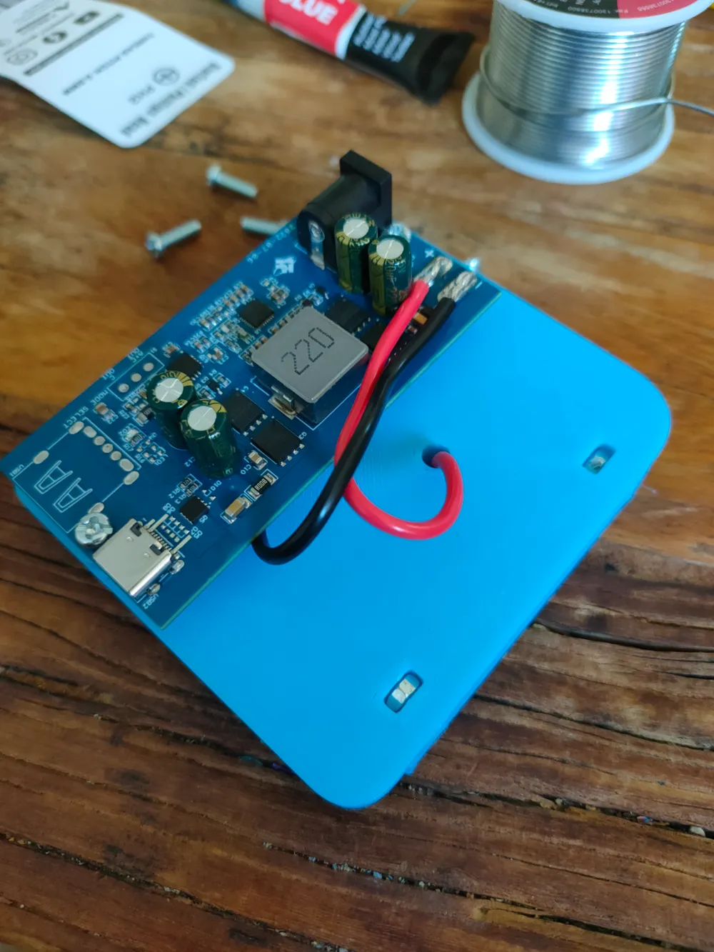
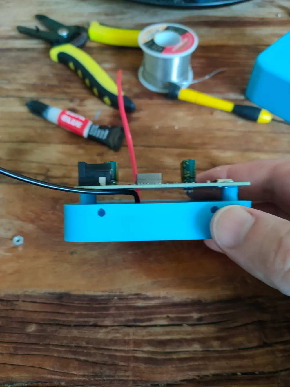
- Mount and screw in the SW2303 board onto the base ensuring to use the printed spacers.
- Solder the wires to the SW2303 ensuring that you have the polarity correct.
- Solder and mount the USB-A board into the top.
- Screw top onto the base.
License
This user content is licensed under a
Creative Commons Attribution-Noncommercial-Share Alike
Comment & Rating (7)