A Writing Robot Arm: The Drawbot


Print Profile(1)

Description
First, an effect shot

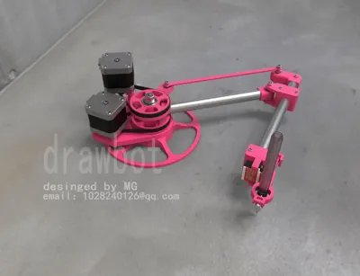
Next, a full family photo

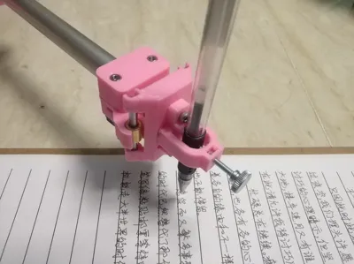
Let's look at the writing effect


Project Introduction
A desktop SCARA robotic arm, with a motion mechanism consisting of two 42 stepper motors and one 9g servo motor. The control board is a Mega 2560 and RAMPS 1.4. Other components are mainly 3D printed parts. The working area is A4 paper size. It uses national standard G-code and currently supports writing and drawing functions
QQ group for discussion 791947714
See test videos
https://youtu.be/NTBxLTUPyTU?si=kK8MbXBvQ_6qLob7
https://youtu.be/tPbYbp5LPhs?si=99UB9mAYLIAaEC__
https://www.youtube.com/watch?v=JfaiAnQvb0s
This project has been in progress since last month. The structure and code have been revised many times. Also, I've been too busy to post and share, so these past two days I'll print some parts and release an assembly tutorial
The software required is as follows (both links contain the same content, just download one)
Baidu Netdisk (for users in China)
https://pan.baidu.com/s/18yXWUpLg42WciHy6xodiBA?pwd=krjr 提取码: krjr
Google Drive (for global users)
https://drive.google.com/drive/folders/1Z0zM5VJ--ebthopvkgDU_kdO5pZJhkqG?usp=drive_link
Accessories kit purchase address
https://item.taobao.com/item.htm?id=1014022063556&mi_id=0000RvyG5r5gFKexPHN8P56AbPpiArThKv0HzF9AfO1-lg0&spm=a21xtw.29178619.0.0&xxc=shop
---------------------Mechanical Installation Tutorial-------------------
All parts used in the Drawbot, except for the printed parts and aluminum tubes, are standard components. The BOM table has been compiled and is shown below


Install the pen clip

If the servo cable is not long enough, extend it to 80cm. Install the servo bracket on one end of the longer aluminum tube, then install the servo. Thread the servo cable into the tube for hidden and neater wiring


Install the main and sub arms; the indicated hole center distance is 200mm

Indicated hole center distance 50mm

Due to cutting errors in the aluminum tubes, ensure the dimension shown in the diagram is 180mm during installation

Install the motor mount

Install the pulley, making sure to put on the timing belt beforehand and not forget it

The limit switch is normally closed. If you bought a normally open type, modify the wiring yourself, with the contact plate facing down

Install the stepper motor

Install two M4 screws in reverse as shown

Plug in the motor wires, wrap them with cable sleeves, and the mechanical part is complete

The electrical wiring diagram is as follows. For the servo, red is positive, black is negative, and brown is the signal wire. All pins under the 4988 driver module must be short-circuited to set the stepper motor to 16 microsteps. The power supply should be 12V with current greater than 2A
ATTENTION!!! The 12V power supply plugs into the red RAMPS 1.4 board, not the blue Mega 2560 board underneath. Plugging it into the wrong one can easily burn the mainboard
For the stepper motors, plug them in without regard to polarity first. If during later debugging, the home return direction is not towards the limit switch trigger, then reverse the motor connection

If the motor only jitters and doesn't rotate, there's a problem with the motor wiring sequence. Test with a multimeter; a pair that's short-circuited is one phase. As shown in the figure, the two red wires on the left are conductive and form one phase, and the two bright blue wires on the right are also conductive and form another phase. If the wire sequence is incorrect, use tweezers to pry open the terminals and swap them

---------------------Debugging Tutorial-------------------
Connect the Mega 2560 to your computer, open Device Manager - Ports, and find the corresponding port. If the computer cannot recognize the control board, you will need the control board driver, which you can request from the vendor

Use xloader to flash the hex firmware. Select the corresponding port, baud rate, and mainboard settings as shown in the figure, then click upload

Open Robotic Arm Master, select the corresponding port to connect

If the following return value appears, the connection is successful. If no return value appears, simply press the button on the control board

Software Interface as follows

Common control commands are as follows
G1 X10 Y10 linear movement
G28 home, needs to home after each power-on to determine the robotic arm's position
G90 switch to absolute coordinate system
G91 switch to relative coordinate system
G94 switch to Cartesian coordinate system
G95 switch to angular coordinate system
M3 servo pen down move to default pen down angle
M3 S15 servo rotates to 15 degrees
M4 L10 T40 set default pen down angle L, default pen up angle T (after using M4 to modify pen up/down servo angles, then use M3 M5 commands to raise/lower the pen to confirm if the angles are appropriate)
M5 servo pen up move to default pen up angle M92 X48.8 Y48.8 set motor resolution. If the motor step angle is 1.8° and it's 16 microsteps, just use the factory settings
M203 X2000 Y2000 set maximum motor movement speed
M201 X1000 Y1000 set motor movement acceleration
M205 X0.8 motor movement smoothness (explained below)
M503 view robotic arm settings parameters
M501 load user parameters (parameters saved to EEPROM)
M502 restore factory settings
M500 save user parameters (save to EEPROM)
M370 define current position as coordinate origin
M700 automatic calibration
All parameter modifications must be saved with M500, otherwise data will be lost after restarting
After the first connection, you need to send M502 to restore factory settings. Then, position the machine to the angle shown in the diagram, with the main arm parallel to the side of the motor mount, and a 45° angle between the main and sub arms. A4 paper can be folded to obtain a 45-degree angle

Click the automatic calibration button. The robotic arm will automatically home and trigger the limit switch. It will then determine the robotic arm's angle by calculating the number of steps moved to trigger the limit, complete calibration after a few seconds, and then send the M500 command to save the settings
After calibration is complete, next time you power on, simply return to the home position (click the small/medium house icon in Robotic Arm Master, which is the G28 command). If the robotic arm is reassembled, recalibration will be necessary
If lines are not straight after calibration, please confirm the accuracy of the following 3 dimensions after installation: both main and sub arms are 200mm long, and the distance between the center of the main arm and the main arm linkage bearing is 50mm

Send G28 to return to the HOME point, import the G-code exported by the G-code generation software, and you can start writing happily
The coordinate system is defined as follows: the X-axis is parallel to the side of the motor mount, the origin is offset from the rotation center as shown below, and the writing range can cover an entire A4 paper

------------------------ ----Control Code Section-------- -------------------------
The control board acts as the lower machine, its role is to interpret G-code sent from the upper machine. G-code contains motion coordinate values and some control commands. For motion control, the lower machine converts G-code into pulses to control stepper motors. Key here are the forward and inverse kinematics functions: determining the robotic arm's angles from known end-effector coordinates, or determining end-effector coordinates from known robotic arm angles
In most industrial SCARA robotic arms, the secondary arm's control motor is located on the main arm and secondary arm. The motor controls the angle between the main arm and secondary arm, which is a 'relative' angle SCARA. See figure below
Similar to the Drawbot's parallelogram structure, the secondary arm's motor controls the angle of the secondary arm relative to the world coordinate system, which is an 'absolute angle' SCARA
By transmitting through a timing belt, the motor is moved to a fixed base, also an 'absolute angle' SCARA
The motion algorithms for the two structures are slightly different. Marlin's built-in SCARA algorithm belongs to the 'relative angle' SCARA, which is easily overlooked here
Drawbot forward kinematics algorithm is as follows
void calculate_SCARA_forward_Transform(float f_scara[3])
{
float x_sin, x_cos, y_sin, y_cos;
x_sin = sin(f_scara[X_AXIS]/SCARA_RAD2DEG) * Linkage_1;
x_cos = cos(f_scara[X_AXIS]/SCARA_RAD2DEG) * Linkage_1;
y_sin = sin(f_scara[Y_AXIS]/SCARA_RAD2DEG) * Linkage_2;//Use this formula when the Y motor controls the rotation angle of the secondary arm relative to the world coordinate system
y_cos = cos(f_scara[Y_AXIS]/SCARA_RAD2DEG) * Linkage_2;//Use this formula when the Y motor controls the rotation angle of the secondary arm relative to the world coordinate system
delta[X_AXIS] = -x_cos - y_cos - SCARA_offset[X_AXIS]; //Get X value in user coordinate system
delta[Y_AXIS] = x_sin + y_sin - SCARA_offset[Y_AXIS]; //Get Y value in user coordinate system
}
SCARA_RAD2DEG is the radian-angle conversion constant, i.e., 180/π. Trigonometric functions use radian calculations, so all angles must first be converted to radians. Calculate x_sin x_cos y_sin y_cos using trigonometric relations
The yellow vector in the figure represents the end-effector position in the world coordinate system, (-x_cos - y_cos, x_sin + y_sin). Then subtract the user coordinate offset SCARA_offset to get the end-effector coordinate values in the user coordinate system
Inverse kinematics algorithm is as follows

void calculate_delta(float cartesian[3]){
float SCARA_pos[2];
static float SCARA_C2, SCARA_S2, SCARA_K1, SCARA_K2, SCARA_theta, SCARA_psi;
SCARA_pos[X_AXIS] = -cartesian[X_AXIS] - SCARA_offset[X_AXIS]; //Get X value in world coordinate system and negate it
SCARA_pos[Y_AXIS] = cartesian[Y_AXIS] + SCARA_offset[Y_AXIS]; //Get Y value in world coordinate system
SCARA_C2 = ( sq(SCARA_pos[X_AXIS]) + sq(SCARA_pos[Y_AXIS]) - (float)L1_2 - (float)L2_2 ) /(2*Linkage_1*Linkage_2);
SCARA_S2 = sqrt( 1 - sq(SCARA_C2) );
SCARA_K1 = Linkage_1 + Linkage_2 * SCARA_C2;
SCARA_K2 = Linkage_2 * SCARA_S2;
SCARA_theta = ( atan2(SCARA_K1, SCARA_K2)-atan2(SCARA_pos[X_AXIS],SCARA_pos[Y_AXIS]) ) ;//Main arm rotation angle, i.e., angle between main arm and -X axis
SCARA_psi = atan2(SCARA_S2,SCARA_C2) + SCARA_theta;//Secondary arm rotation angle, use this formula when the Y motor controls the rotation angle of the secondary arm relative to the world coordinate system
delta[X_AXIS] = SCARA_theta * SCARA_RAD2DEG; //Main arm rotation angle converted to radians
delta[Y_AXIS] = SCARA_psi * SCARA_RAD2DEG; //Secondary arm rotation angle converted to radians
}
}
cartesian[X_AXIS][Y_AXIS] are coordinate values in the user coordinate system. Adding SCARA_offset yields coordinate values in the world coordinate system
Where SCARA_pos[X_AXIS] vector direction is to the right, opposite to the original coordinate X direction, hence negated
#define L1_2 sq(Linkage_1)
#define L2_2 sq(Linkage_2)
L1_2 L2_2 are the squares of the pre-defined arm lengths
Then the square of the distance of line AB is sq(SCARA_pos[X_AXIS]) + sq(SCARA_pos[Y_AXIS])
In triangle ABC, with three side lengths known, cosC=(a^2+b^2-c^2)/2ab can be derived from the Law of Cosines
The supplementary angle of α is
arccos [ ( (float)L1_2 + (float)L2_2- sq(SCARA_pos[X_AXIS]) - sq(SCARA_pos[Y_AXIS]) ) /(2Linkage_1Linkage_2) ]//This is pseudocode; C language does not have an arccos function
SCARA_C2 is the negation of the cosine value of the supplementary angle
SCARA_C2 = ( sq(SCARA_pos[X_AXIS]) + sq(SCARA_pos[Y_AXIS]) - (float)L1_2 - (float)L2_2 ) /(2Linkage_1Linkage_2);
Convert the cosine value of α to a sine value
SCARA_S2 = sqrt( 1 - sq(SCARA_C2) );
Calculate SCARA_K1 SCARA_K2 based on trigonometric relations
From the figure, it is known that SCARA_theta +δ+β =π/2 and δ+γ =π/2
Then SCARA_theta =γ-β = ( atan2(SCARA_K1, SCARA_K2)-atan2(SCARA_pos[X_AXIS],SCARA_pos[Y_AXIS]) )
SCARA_psi = α+SCARA_theta = atan2(SCARA_S2,SCARA_C2) + SCARA_theta
Multiply by the radian-angle conversion factor to get the main and sub arm angle values
delta[X_AXIS] = SCARA_theta SCARA_RAD2DEG
delta[Y_AXIS] = SCARA_psi SCARA_RAD2DEG
Supplementary explanation of motion smoothness parameter settings: motion smoothness is the CNT value in industrial robots. Because velocity cannot change instantaneously, in polyline motion, if moving precisely to a vertex, the vertex velocity would be 0 or very slow. Therefore, a polyline is replaced by an arc, and the acceleration trapezoids of the two lines intersect. The set value is the velocity at the intersection point. The higher the setting, the faster the speed and the larger the rounded corner created in the path
License
You may create derivative works based on this object, provided that all such derivative works are published exclusively on the MakerWorld platform and include proper attribution to the original creator. You may not share, upload, host, distribute, or publish this object—or any derivative work of this object—on any other digital platform, marketplace, or distribution channel. Commercial use of this object and any derivative works is strictly prohibited. This includes, but is not limited to, selling, renting, sublicensing, or using the object in any context in which you receive monetary compensation or other financial benefits.
Comment & Rating (8)