M1A2 Abrams Hunter-Killer


Print Profile(1)

Bill of Materials

Description
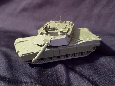
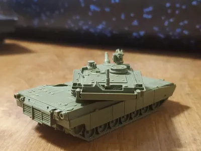
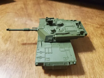
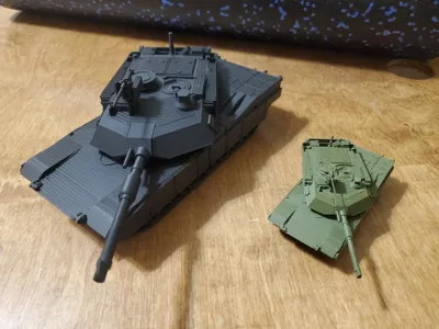
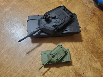
This is a detailed model of the M1A2 Abrams System Enhancement Package tank with the M153 high-profile Common Remote Operated Weapons System. I've never been super-satisfied with the details of any of the other Abrams models floating around the 3D printing space, so I decided to take this opportunity to follow the mantra “if you want it done right, do it yourself”.
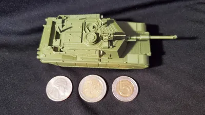
The challenge for this one was to push the limits of the 0.4mm nozzle in producing small details. Therefore, the tank is in a weird scale (approximately 1/80). To get it in 1/72, increase the size of all the parts to 108%. For 1/35, bump the size up to 220%. In its original scale, the tank is sized to fit a 608 bearing between the turret and hull. I have included a 3d printable blank to allow it to be assembled without the use of a bearing, which may be necessary at different scales. Scaling and printing a bearing will probably also work, but that's outside of my purview.
This model was designed with the limitations of an FDM printer in mind. I have tested all the parts on a 0.4mm nozzle, and they work well. This model is great for 0.2mm nozzles (printed the turret on one), and would be amazing if resin printed. I would not recommend any nozzle larger than 0.4mm at the default scale. It looks good scaled up to 1/35.
As a little background, I've been a tanker for the past 12 years, and an Abrams Tank Commander for a little over 7 years. I've done my best to do the tank I'm serving on justice, but nobody's perfect. If I'm missing a detail that isn't due to nozzle size (and if you're correct about that detail), leave a comment and I might release an upgrade part just for you!
Please note that this model requires glue.
I've printed and tested this model well over a dozen times. The print profile has all of the correct orientations and custom settings, but for those of you printing from the .stls, here's an overview:
General: If printing at default size, 0.12mm or 0.08mm layers are recommended. Print using Arachne Engine.
HULL:
Left Track Assembly.stl: Clone this and mirror it to get the right tracks. Figuring out settings for this piece was the hardest part of the entire design. I've gotten the best results printing it laying on the “inside” with the road wheel arms touching the build plate, then using tree supports with 0.16 top Z distance.
Left Skirt Assembly.stl: Clone and mirror for Right skirts. No special settings needed.
Lower Hull.stl: Print with the top surface (the side with the big hole) to the bed with supports enabled.
Upper Hull.stl: Print with the bottom surface (large flat section) to the bed. No supports required. You can also print this on its back surface, which reduces the obvious stepping on the front slope, but I've found that really badly affects the panel line quality on the back deck.
Rear Assembly.stl: Print on the large flat surface, no supports required. Please note, the slicer may give you a warning about floating cantilever. This is false, it prints fine.
Front and rear hull alignment blocks: Print these however you feel like.
TURRET:
Lower Turret V2.stl: This is the weird one. Best quality is from printing on the rear of the turret, with the part angled upwards. Needs at least a 3mm brim, and supports with a 30 degree or more threshold. The slicer wants to put the seams at the side of the turret on the tow cables, this will mess them up. I painted a seam down the middle of the bottom and it worked well.
Upper Turret V2.stl: Print flat on the bottom, no supports needed. This part will greatly benefit from smaller layer heights.
Mantle and Gun Barrel.stl: Paint on some supports. No seriously, put as many tree supports on this as you can. It doesn't actually need supports, but if you don't, it will not come out well. Essentially, the printer needs to be printing something else between layers on this part. Alternatively, you could print two of these at once with no support, as long as they're not close to each other on the build plate. This problem isn't nearly as bad if you scale up the model. Paint a seam on the bottom of the gun.
Bustle Rack.stl: Print on the flat bottom, no supports. Once again, the warning about floating cantilever is a lie.
L Sponson.stl: Clone and mirror for right sponson. Print flat on the inside surface, it's the only completely flat surface on the part.
Center Bearing Blank.stl: Only needed if you aren't using a 608 bearing (or appropriately scaled printed bearing). Print on a flat surface with no supports.
CROWS:
(Note: I've separated this assembly into its own build plate for people who might not want to print it. It's EXTREMELY small and fragile, even scaled up to 1/35.)
CROWS Base and Servo.stl: Print on the flat back, no supports, at least 3mm brim. Like the gun tube, the printer needs to be printing something else between layers for this for the entire height of the barrel. Unfortunately, I don't think you can get away with just printing 2 at a time due to the extremely thin geometry. I've included a very precise block in the print profile to give the layers time to cool. If printing from the .stls, just throw something else on the bed that's taller than this piece and you'll be fine. Use a scraper to remove this part from the bed, and don't squeeze it too hard or it will shear along the layer lines.
CROWS Ammo Box.stl: Print on the base of the brass catch basket (the basket-shaped part) with supports enabled.
.50 Rear.stl: Print on the flat bottom with a minimum 3mm brim.
ASSEMBLY:
- Slide the front and rear hull alignment blocks into the lower hull.
- Line up the slots on the upper hull and press the upper hull onto the alignment blocks (Glue if necessary)
- Place glue on the top surface of the left track assembly and on the upper portion of each road wheel arm. With the sprocket towards the rear of the tank, line up the support rollers along the top of the track with the “U”-shaped guides on the lower hull and glue in place. Repeat for the right track assembly.
- Place glue on the bottom of the rear exhaust assembly. Line the rear assembly up with the tab on the back of the upper hull and glue in place.
Place glue along the very bottom of the left side of the upper hull. Line up the left skirt assembly with the front fender extension and the rear fenders on the rear assembly, then glue in place. Repeat for the right skirt assembly.
The hull is now complete. Insert a 608 bearing, properly scaled printed bearing, or the center bearing blank into the hull.
- Slide the upper and lower turret parts together, and glue in place (note: some sanding may be required depending on your build surface.)
- Place glue on the top half only of the boxes in the bustle rack where they meet the turret. Place glue on top of the extension on the rear of the upper turret part. glue the pieces together, ensuring the bustle rack is level with the upper and lower turret when viewed from the sides and rear.
- Place glue on the flat inside portion of the left sponson. line up the top of the sponson with the nearest edge on the turret, and line up the 3 sponson rails with the bustle rack rails, then glue in place. The sponson should be touching the bustle rack. Repeat for the right sponson.
Place glue on the flat base of the mantle and gun assembly, then glue it to the slot in the front of the turret. The bottom of the gun mantle should be flush with the lower turret.
The turret is now complete. Insert the turret into the bearing or blank mounted in the hull.
- Place glue on the inside of the CROWS ammo box, and glue it to the left side of the CROWS base and servo assembly, ensuring the basket on the ammo box is flush with the rear of the base and servo assembly.
- Place glue into the top channel on the CROWS base and servo assembly, then install the .50 rear into the channel.
- Glue the completed CROWS assembly into the square recess on top of the gunner's sight on the turret.
As usual, I hope you enjoy. I put a lot into these models, and I always appreciate a like or a boost if you enjoy them. Also, if you show up to ABOLC with these for your terrain models, I'll give you a crisp high five before tearing into your TMK (IYKYK).
License
You shall not share, sub-license, sell, rent, host, transfer, or distribute in any way the digital or 3D printed versions of this object, nor any other derivative work of this object in its digital or physical format (including - but not limited to - remixes of this object, and hosting on other digital platforms). The objects may not be used without permission in any way whatsoever in which you charge money, or collect fees.
Comment & Rating (49)