Search models, users, collections, and posts
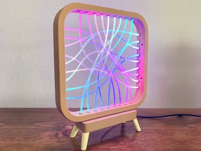
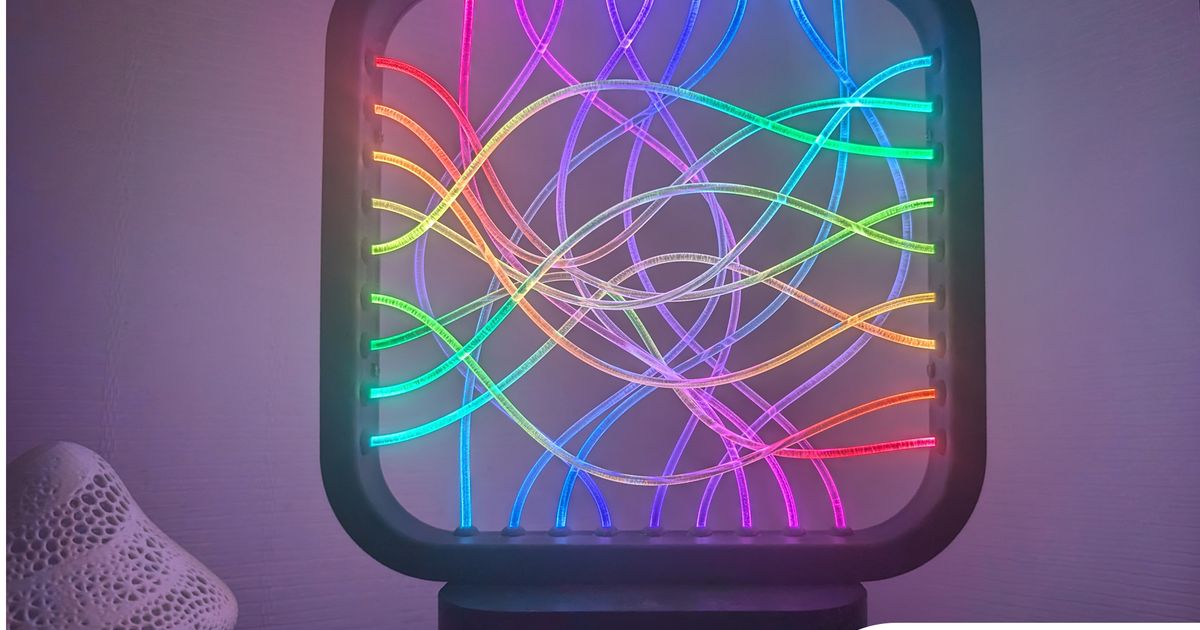
Fiber Optic LED Light Mid-Century Modern
Remixed by
IP Report


Print Profile(2)

0.6mm nozzle, 0.24mm layer, 2 walls, 15% infill
Designer
6.2 h
5 plates

V2 Updated parts 0.2mm layer, 2 walls, 15% infill
Designer
10.4 h
6 plates
Open in Bambu Studio
Boost
34
126
4
1
20
7
Released
Description
This is a slight remix of the awesome model by @urzhiataer from Printables. The entire base was redesigned to give the model more aesthetics and a Mid-Century Modern vibe.
Colors I used: Matte PLA Wood Brown, Matte Beige
Urzhiataer's Instructions from the initial model.
BOM
- 5 meter of fiber (diam 3mm) (https://fr.aliexpress.com/item/1005002987759286.html)
- 1x ESP32 WROOM
- 1x USB C (https://fr.aliexpress.com/item/1005007148475800.html)
- 1 meter of ws2812b (36 leds) (60 leds / meters) IP 30
- 5v 2/3A usb power
- optional ESP32 case (here i printed this : https://makerworld.com/en/models/186291)
- some wire (24 - 20 AWG)
- 4 x M3-12 (to attach the frame to the base) or glue (not recommended)
- 4 x M3-12 (to attach the lid under the base)
- 4 x M3 - 6 (to close the frame with the lid frame) or glue
Instruction
- print the elements
- Prepare the ESP32 by installing WLED (directly from the WLED site https://kno.wled.ge/ ; https://install.wled.me/ )
- cut 4 strips of 9 LEDs, solder them with about 5cm of wire (24-20 AWG) and a length of 15 cm at the input of the LED strip. Pay attention to the direction of the LEDs (look at the small arrow).
- Test the leds before assembly
- Cut 18 pieces of fiber (25/23 cm) Tip, make a cut with a knife, then break the fiber at the notch for a clean cut.
- Place the 4 ribbons in the frame, make sure that the LEDs are facing the holes. Start placing the pieces of fiber, resting on the LEDs, this will hold the strip in place)
- Once everything is in place, test again
- Close the frame. (4 M3- 6 like picture) or glue
- Pass the input cables through the hole in the base, attach the frame to the base. Place the USB plug, solder the +5V to the +5V of the LEDs and another for the +5v of the ESP. Same with the GND.
- Connect the +5v, the GND, and the data wire of the LEDs to the ESP32
- Test again
- You can place the ESP32 in the case, and glue the case in the base (cleaner) or directly glue the ESP32 with a glue gun in the base)
This remix is based on
License
This user content is licensed under a
Creative Commons Attribution-Noncommercial-Share Alike
Comment & Rating (4)