X-Axis Drill Guide for Idler Removal/Conversion


Print Profile(2)


Description
DISCLAIMER: THIS MODIFICATION CAN/WILL VOID YOUR WARRANTY. PERFORM THIS MODIFCATION AT YOUR OWN RISK.
Background
This is a drill jig for locating holes in order to remove the pin holding the smooth idler pulley on the X-Axis in order to change out for a toothed pulley.

Bill Of Materials
- (Recommended) QTY: 1 - X-Axis Carbon Assembly
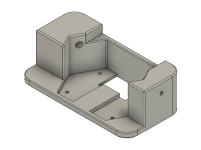
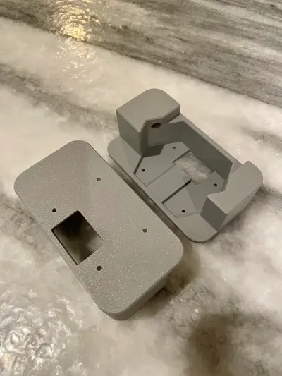
- QTY: 2 - Printed Drill Guide
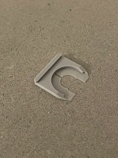
QTY: 2 - Printed Shim Tool
0.2mm nozzle at 0.1mm first layer and 0.05mm remaining layers with maximized wall count
- QTY: 1 - 5mm (0.201" or #7) Drill Bit
- QYY: 1 - 3mm (0.125") Drill Bit
- QTY: 1 - 2mm hex key (included with printer) or something similar to use as a punch to remove the pin and a rubber mallet
QTY: 2 - Genuine Gates 20T, 6mm Belt Width, 5mm Bore, toothed idler
M-IDLER-T-GT2-P20-6-A-P5-H100
https://www.filastruder.com/collections/gates/products/gates-2gt-idler?variant=15443755728967
https://e3d-online.com/products/gates-belts-pulleys-and-idlers?variant=41205372289083
QTY: 4 - 5mm ID x 7mm OD x 0.2mm TH shims
https://www.amazon.com/dp/B091YBHD43?ref=ppx_yo2ov_dt_b_fed_asin_title
Idler Removal
- I highly recommend completing this installation using a new X-Axis Carbon Rod Assembly. It will allow you to work on the new assembly without having to remove your old assembly until the modification is successfully completed. You will need to print items prior to performing the modification. The drill guide was designed taking measurements from my specific carbon rod assembly, however, it is possible that your assembly may be different as Bambu actively upgrades their design while in production.
Print 2 of the drill guides. This helps to support the x-axis carbon rod assembly while drilling and ensures the holes have not become too large from the previous drilling operation if you were to re-use on the opposite side.

- By hand, chase the holes of the printed guide and ensure the drill bit is a tight fit and perpendicular to the entry face
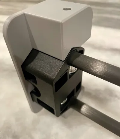
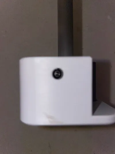
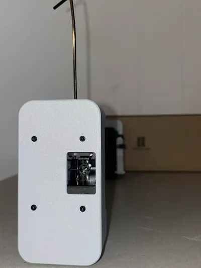
Attach the drill guides to the carbon rod assembly using QTY:4 per side of the 2mm plastic forming screws securing the Y slider cover plate. You can also use a clamp to hold the guide onto the rod assembly. Pay close attention to orientation to ensure you remove the drill to remove the correct pin/pulley.

Ensure the 5mm hole is concentric with the pin hole/pin by using a flash light to look down the guide. If it is not, ensure the assembly is completely seated against the print and check again. Ensure the guide is installed in the correct orientation for the pin you are trying to remove as the pulleys are NOT symmetric about the rod centerline.

Using a 5mm or 0.201 (#7) drill bit, slowly start to drill out the carbon rod. Once you feel the drill bit hit the pin, stop drilling. This hole is needed to create clearance to be able to drive the pin out past the rod. In the image below, you can see where the drill bit contacted the pin

- Using a new/sharp 3mm or 0.125" drill bit, VERY slowly drill through the opposite side. You will be drilling on a sloped surface then along the rib so your drill bit will naturally try to flex and wander, so it is important that the drill bit is very sharp, you are perfectly perpendicular, and move slowly. Mine initially did not come out perfect but was was able to wallow out/angle the drill slightly to dig into the rib a little bit more.
Once both the 5mm and 3mm holes are drilled, you can use your included 2mm hex key or punch to tap out the pin through the 5mm hole. I confirmed it can be done with the included 2mm hex if you take your time (mine ended up bending while tapping). I then used a proper punch on the other side and it was significantly easier.

Repeat for the opposite side. When you are done, you will have QTY: 2 pins, QTY: 2 smooth idler pulleys and QTY: 4 shims (5mm ID X 7mm OD x 0.3mm TH).


Idler Installation
First, place one of the printed shims on top of the Gates idler pulley.

Carefully insert into the carbon rod end block. Using a hex key or similar, insert through the pin hole and move around to line up the idler and shim. Using a flashlight, look down the bore to verify alignment. Once the pulley is aligned, insert the pin by hand and push in until it reaches the idler and hold both temporarily in place.

Flip the carbon rod assembly over and carefully insert/wedge the top 5mm x 7 mm x0.2mm shim between the idler and end block. The shim should be center and flush with the end block before proceeding.

Using the printed shim tool, carefully slide between the idler and the housing, while keeping the shim centered between. Fully insert this printed tool until it bottoms out on the idler flange.

Verify the shim is not blocking the hole by looking through the backside of the end block.

Once you verify the bore is clear, tap the remaining length of the pin in until it bottoms out against the rib. I used the printed drill guide to hold the carbon rod assembly while I tapped the pin into place.

Enjoy!


License
You shall not share, sub-license, sell, rent, host, transfer, or distribute in any way the digital or 3D printed versions of this object, nor any other derivative work of this object in its digital or physical format (including - but not limited to - remixes of this object, and hosting on other digital platforms). The objects may not be used without permission in any way whatsoever in which you charge money, or collect fees.
Comment & Rating (7)