
Project: 2M/70cm J Pole antenna frame HAM Radio
Print Profile(1)

Description
Project: 2M/70cm J Pole Ladder antenna for HAM Radio
I had purchased a 2M ladder antenna and it worked well. Although being portable and could roll up to use at different locations, it soon developed a weak point and the solid wire broke. And then the solder joint broke, etc... Being a HAM, I wanted to build my own antenna and tried several different types of wire. I experimented mostly in the 2M range: HAM, MURS, marine, etc… (Also harmonics are good enough in the 0.7M range.) Though the lengths were always close to the same length (Wavelength), I found that 16G multi-strand strand electrical copper wire worked best for me. I designed a modular antenna structure to accommodate the diameter of this wire and the different wire lengths (from my math). It also helped keep the wire parallel. I found this to be more durable than the commercial ladder antenna with the solid wire. I have rolled it up and unrolled many times. I use a Jackite fiber glass pole or just string it up a tree to hang away from other metal objects or poles. WORKS GREAT!
NOTE: The 3D model is complete and no extra parts are needed to assemble the parts printed. However, to make a functional antenna you will need the following:
What you will need:
- A graphical Antenna Analyzer. You will have a hard time if you do not have access to a graphical antenna analyzer. I use the RigExpert 650AA since it will quickly draw a graph of the SWR range. There are other manufacturers out there so please leave comments on how yours worked.
- Soldering iron: To solder the coax core to the long side (A) and the ground to the short side (B) of the wire on each side of the loop (C). See Chart for lengths.
- Wire: I used 16G multistrand wire. Print a single 1” section and determine if you need to scale up to fit your wire.
- COAX with Connector of choice. I used 1 foot of RG58 coax with a SO-239 connector on one end since all my Coax cables are PL-259 as a standard. But any connector you want to use should work fine. The other end of the short 1 foot cable will be soldered to the wire as indicated. RG58 is what I designed the coax mount section.
- Wire cutters for adjusting frequency as indicated using Antenna analyzer. Tuning the antenna.
- Optional Ferrite core on coax under loop to smooth out the frequency. Not really necessary but it is more smooth with the ferrite core. Find one that snuggly fits the coax you are using. For my RG58 coax, I used 7mm ferrite core.
- Tie wraps: I used about 5 6” tie wraps to secure the coax near the solder segment.
- 3D Printer to print the following plate. I used PETG for flexibility and strength on my Bambu Lab X1C.
- Layer height of .10
- No supports
- Textured or Smooth plate
- OTHER:
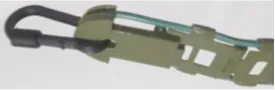
Carabiner: Instead of a paracord loop, I printed a nice sturdy carabiner about 2” long that fit nicely through the top hole of the antenna. I do not know where I got it from but this one worked well and was easily scalable.
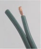
Example of wire: Single or dual wire will work fine. The wire I used was dual lamp cord wiring. The two wire cords were easily pulled apart, so a single multi-strand wire was used for each antenna. The diameter of the wire will need to slide through the guides on the support structure.
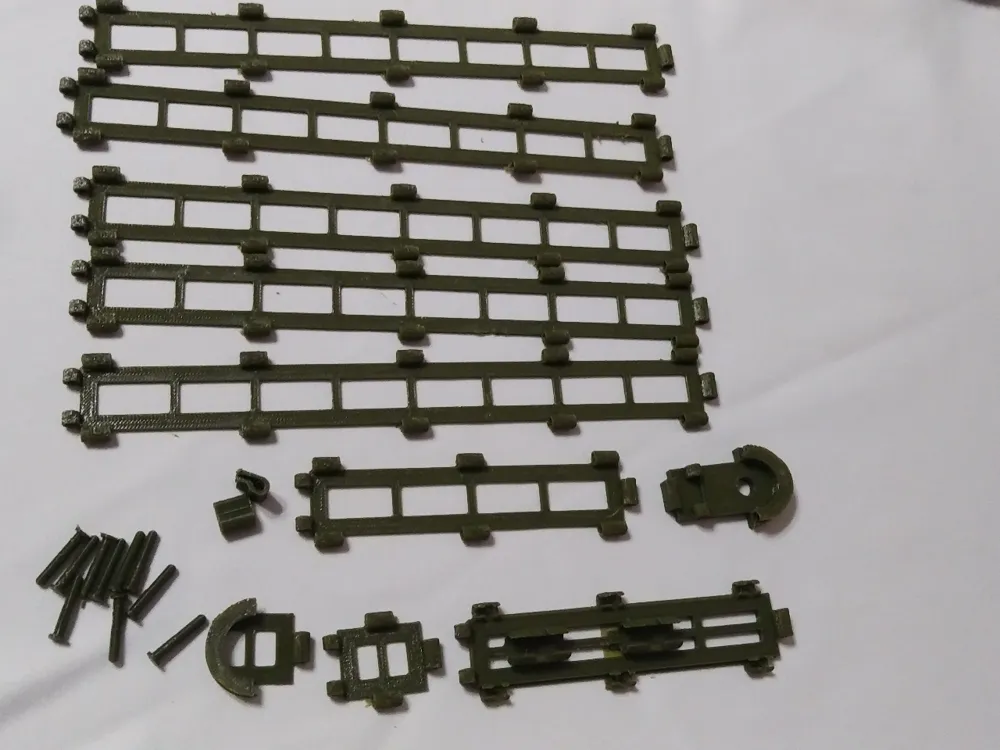
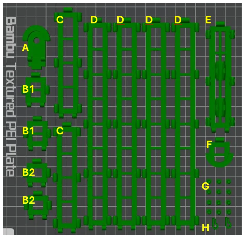
Parts on the plate: This should be about right for any 2 Meter antenna. You can print individual sections to make the wire ends end up closer but at least an inch apart as described later in this instruction.
Print one 1” (B) section to verify wire guides will work with your wire. Determine scale % to scale up each piece if needed.
- Top section – Qty 1
- Short sections – Qty 4
- 4” sections – Qty 2
- 8" sections – Qty 4
- 4” Coax Mount section – Qty 1
- Bottom Section – Qty 1
- Axle Joint Pins – Qty 12
- Clips – Qty 2
Assemble Antenna support ladder structure:
| 1. Start assembly in order of the list above using Pins to lock the sections in place. The last part of the pin has a ring to lock it in place. You can push it out if needed to remove or replace a section. | ||
| 2. Connect Coax Mount Section (E) and Bottom (F) to make the bottom assembly and hold to the side. You will use this later. | 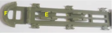 | |
| 3. The Top (A) and Bottom (F) was designed with supports that will need to be cut out to lay wire in grove. Then connect to the first section to snap in place. | 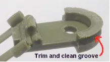 | 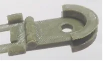 |
| 4. Be careful not to break guides when snapping the pins in place. Be careful when using pliers to avoid breaking guides. The pins can be pushed out from the other side if needed. | 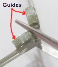 | |
Now with the TOP and the BOTTOM assembled, you can wait to build the rest after cutting wire and soldering to the loop.
Wire length chart by frequency:
- The length of wire to cut starts with the target frequency.
- Example, if you want midpoint to be about 152 MHz for MURS frequencies. Use the midpoints of 150 and 155 of A+B+C=Total Wire length. Otherwise, use the length as shown for the frequency you want.
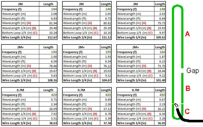
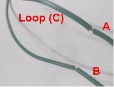
2. Create a split in the plastic jacket of the wire to make the sections about the correct lengths. The important section is the Loop to get as close as possible. Loop C starts at length B. Estimated total wire length is what to measure.
3. Use bottom assembly to hold coax and wire off plastic for soldering aware from plastic to avoid melting. Pre-tin the wire and coax.
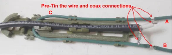
4. Solder coax core to long side of loop where Loop C and Section A meet .
5. Solder Coax ground to short side where Loop C and Section B meet.
6. Trim and Inspect Solder joints
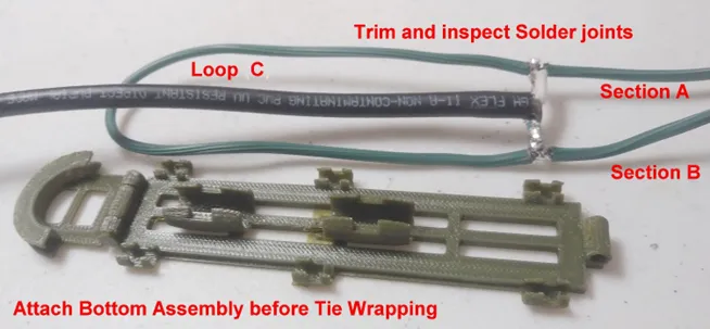
7. Attach bottom assembly to the larger sections and work your way up to the smaller and TOP section.
8. Attach Loop and Coax to the bottom section and feed wire though guides before using tie wraps.
9. If the ends overlap an inch or two, do not worry, you will be cutting while tuning the antenna assembly.
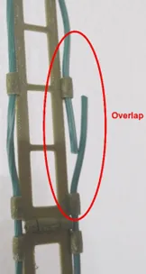
10. Tie Wrap as you like but secure the solder section well and bottom.
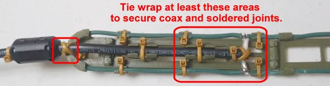
Tuning the Antenna using your Analyzer.
- Using a short cable that you can work with your antenna analyzer, hang antenna away from objects like a beam or hook in ceiling.
- Take an analyzer reading after each cut.
- Trim 1/8” segments from the end of Section B and then take a reading,
- Then trim Section A and take a reading.
- NOTE: Each cut will move the SWR valley to the smaller frequency side and will lower the SWR but only to a point. If you get two movements but not a lower SWR, then stop cutting. You can cut little by little on each side but stop if it stays level or starts to rise.
- Repeat until you get to desired tuning level.
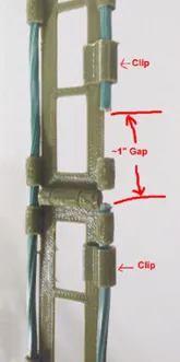
When tuning is completed where you want it, be sure to replace or add segments so the ends are about 1” apart. This will require pulling wire back out from the top and using segments to adjust the ends. The gap helps with SWR.

Waterproofing: you can waterproof with liquid tape / Caulk. Also end of wires. Use just enough to seal.
I have not experienced a noticeable change when sealing the coax solder side and a dab on the end of each cable.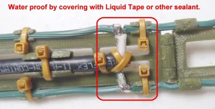
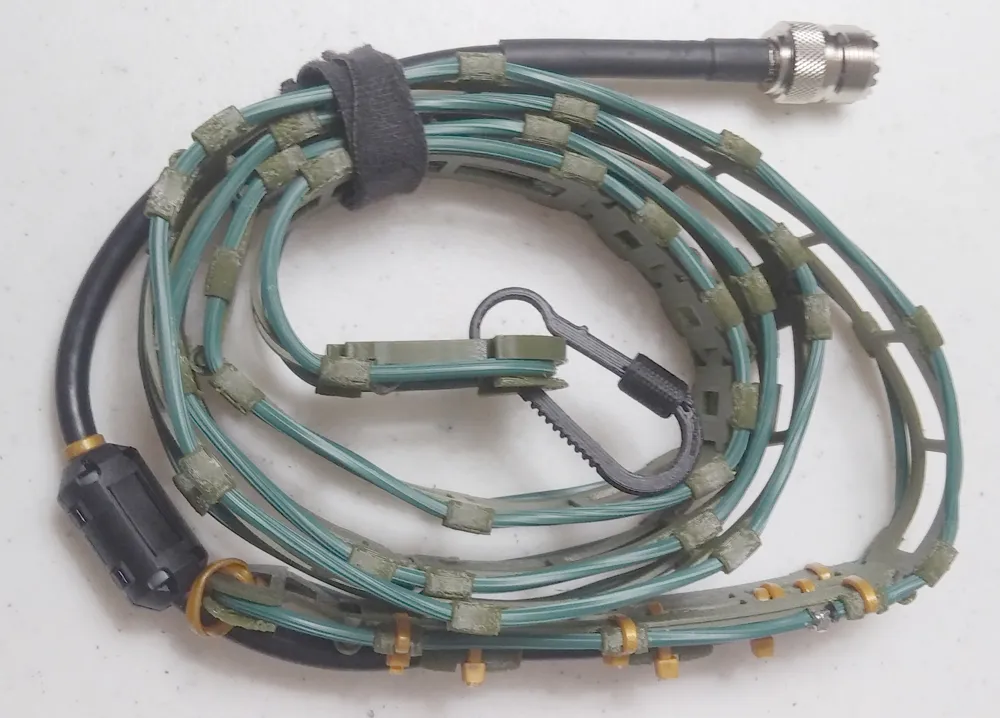
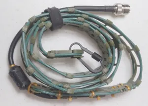
5. Picture of rolled up antenna ready to deploy.
Example of Antenna Results:
Example 1: My goal here was to create a MURS antenna but ended up making a really great HAM antenna as well.
The antenna analyzer results with a Ferrite Core (Green) and without a Ferrite core (Red). Works fine without the ferrite core and I could not tell the difference in Rx or Tx. Both versions work fine but the analyzer graph is smoother with the ferrite core.
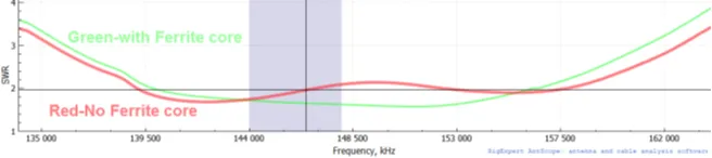
Example 2: I wanted to make a MURS antenna and chose to split the difference on the 150 and 155 MHz charts. My Loop (C) was right at 9.67” for 152Mhz target. After trimming the ends to get it to where I wanted, I achieved these results.

Enjoy,
KD5JUN
John
Documentation (1)
License



Comment & Rating (6)