Search models, users, collections, and posts

CVJ (Constant Velocity Joint) Fidget Toy

Print Profile(2)

All
P1S
P1P
X1
X1 Carbon
X1E
A1
A1 mini
H2D
H2D Pro
H2S
P2S
H2C
X2D
A2L

CVJ - Single Joint
CVJ - Single Joint
Designer
59 min
1 plate
5.0(3)

CVJ - Double Jointed
Designer
1.1 h
1 plate
5.0(1)

Open in Bambu Studio
Boost
45
96
10
7
137
67
Released 

Description

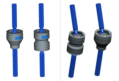
This Birfield-type Constant Velocity Joint is very addictive to fiddle with.
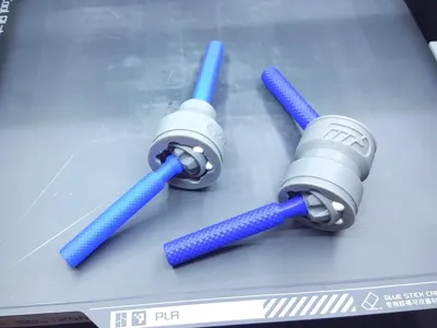
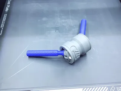
Although it requires two hands to operate it turns pleasantly smoothly, while it will transmit a surprising large amount of torque over a large angle, up to 45° for the single CVJ version, twice that for the double CVJ coupler.
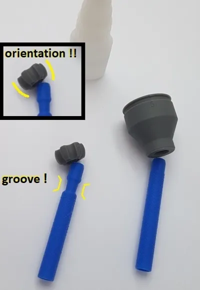
I've added some knurling on the shafts to add grippiness for easier handling.


Interestingly, I've used exactly these type of CVJ's in my RC-car that I designed and built some years ago as it's shown in my banner image, so I know they're very pragmatic, as well.


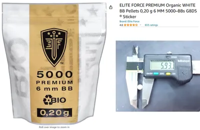
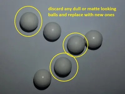
Tolerances for this 'toy' are pretty tight and for smooth operation it's essential to use balls of the right material and dimension.
I've added an image of the BB balls I use for all my CVJ and bearing needs.


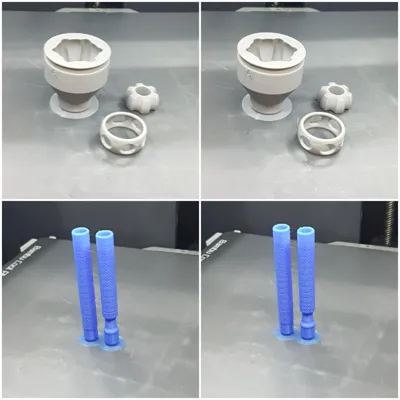
After printing the shafts need to be glued into their respective parts (see images), and it is crucial to take notice of the orientation of the inner race on its (correct) shaft, it will not work when flipped !


Assembly is easy, but a bit fiddly (see the attached image for a schematic guide) :
1. after glueing, glide the cage over the inner race on its shaft, notice: the cage has no orientation, it works both ways
2. insert the combination into the housing part. Attention: tight fit, the holes in the cage should glide over the narrow edges ot the housing
3. maximize the angle between the shafts and by rotating the different parts align the grooves of the housing and inner race with the holes in the cage
4. insert the first ball and by rotating 60 degrees to the next groove incrementally keep adding balls
5. the last ball will go in pretty tightly, but with a bit of force it should snap into place


Please note:
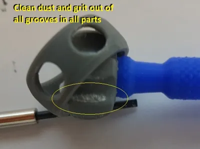
- because of the relative roughness of 3D printed parts dust and grit will accumulate in the grooves and ways after a few days of turning, which will make the joint choppy and jerky: this will need to be cleaned ! 
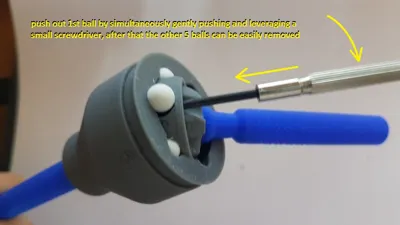
- when dis-assembling, removing the balls is tricky for the first of the six balls, see attached images for some tips and tricks for that, the remaining balls will easily detach
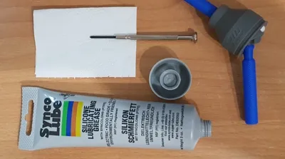
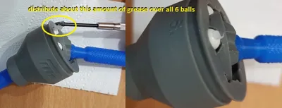
- after a thorough cleaning (wiping down with a rag or cloth), and possibly replacing worn (matte) balls, re-assemble and apply some small drops of grease
- Fortunatey, the cleaning needs to be done only once ! After that it will run for a long, long time
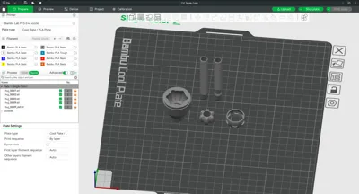
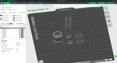
 

Printing :
- as of now PLA is the preferred material due to its hardness, toughness and printing quality, other materials are to be tested
- as the shafts are are long and thin and printed vertically I advise to use a brim
- for all other, rotating parts it is essential to not have a noticeable seam, I use the 'Random' Seam position, I never tried a Scarf joint type seam, might work
- the remaining settings are standard


For anyone interested in some background information see:
http://archive.is/xVEk


Note: as usual, any stereo images are of the cross-eyed type.
Link: https://en.wikipedia.org/wiki/Stereoscopy

Comment & Rating (10)

(0/1000)

My warmest congratulations, thank you for this contribution - a truly working model The 3D printing was unproblematic The entire 3D model was printed with PETG (model + support material) Only the ball cage had to be printed with support material The assembly of the joint itself requires a little practice, but it works out in the end Scaling the model to a smaller dimension should probably be unproblematic A result that delights every 3D printing fan Steel ball diameter 6mm https://www.amazon.de/s?k=sourcing+map+25Stk.Pr%C3%A4zisionskugeln+Steel+balls+6mm+solid+chrome+steel+G10+f%C3%BCr+ball+bearing+wheel&;__mk_de_DE=%C3%85M%C3%85%C5%BD%C3%95%C3%91&ref=nb_sb_noss My practical application example is the connection of a cordless screwdriver to drive a spooler for filament spools
(Edited)
The designer has replied
Show original
0
Reply
Many thanks for your detailed words of appreciation That pleases me greatly Also many thanks for the pictures and of course for the boost I am curious about the mentioned use case In the past, I myself have designed and used similar constant velocity joints (with slightly smaller steel balls) in two other applications Here are links if there is interest https://www.youtube.com/watch?v=vV67iu4Ujqk https://www.youtube.com/watch?v=CIUF9oO1_gw The constructive remarks regarding (support) material are also much appreciated, thank you for that One final remark so that the joint can be used to its maximum potential: the two shafts should actually be applied inversely to achieve the largest possible angle This means: the shaft with the groove should be fixed into the hub, the 'smooth' shaft into the housing See also the image below In the above configuration, the joint works just as well, but with a smaller maximum angle between the shafts I wish you much success with the mentioned project
Show original
0
Reply
The following photos show an application of the constant velocity joint on a spooler which is driven by a cordless screwdriver (1) The constant velocity joint was provided with a corresponding internal square connection on the housing (2) For this purpose, the desired internal square was modeled, printed out, and glued into the housing of the constant velocity joint (3) The other end of the constant velocity joint was retained (original) and serves for connection with the cordless screwdriver
(Edited)
GIF
Show original
0
Reply
Print Profile
CVJ - Single Joint
(1) My warmest congratulations, thank you for this contribution - a really working model. (2) The 3D printing was unproblematic. (3) The entire 3D model was printed with PETG (model + support material) (4) Only the ball cage had to be printed with support material. (5) The assembly of the joint itself takes a little practice, but it works in the end. (6) Scaling the model to a smaller size should be unproblematic. (7) A result that will delight every 3D printing fan.
0
Reply
(1) My warmest congratulations, thank you for this contribution - a really working model. (2) The 3D printing was unproblematic. (3) The entire 3D model was printed with PETG (model + support material) (4) Only the ball cage had to be printed with support material. (5) The assembly of the joint itself takes a little practice, but it works in the end. (6) Scaling the model to a smaller size should be unproblematic. (7) A result that will delight every 3D printing fan. Steel ball diameter 6mm https://www.amazon.de/s?k=sourcing+map+25Stk.Pr%C3%A4zisionskugeln+Steel+balls+6mm+solid+chrome+steel+G10+f%C3%BCr+ball+bearing+wheel&;;__mk_de_DE=%C3%85M%C3%85%C5%BD%C3%95%C3%91&ref=nb_sb_noss My practical application example is the connection of a cordless screwdriver to drive a spooler for filament rolls.
0
Reply
Print Profile
CVJ - Single Joint
The profile uploader has replied
0
Reply
Thanks for your review !
0
Reply
Print Profile
CVJ - Double Jointed
The profile uploader has replied
0
Reply
Thank you for the great review !
0
Reply
Boosted
Print Profile
CVJ - Single Joint
0
Reply
No more

License

This user content is licensed under a Standard Digital File License.

You shall not share, sub-license, sell, rent, host, transfer, or distribute in any way the digital or 3D printed versions of this object, nor any other derivative work of this object in its digital or physical format (including - but not limited to - remixes of this object, and hosting on other digital platforms). The objects may not be used without permission in any way whatsoever in which you charge money, or collect fees.