Darth Maul LightsaberSaber


Print Profile(1)

Description
DarthMAUL Saber
DarthMAUL Saber Arduino code and libraries
https://drive.google.com/file/d/1f50G5wBJoSad_9DOkryAZF6pWBe82mmI/view?usp=sharing
Edit: 28.8.2024 Video - final composition and electronics:
Edit: 28.8.2024 Video - For an idea of how the parts fit together. Some parts need to be glued before assembly!
3D printing
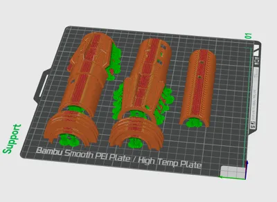
Print the parts on a 3D printer. Maintain the orientation of the parts as shown in the images. Use a minimum of 10 perimeters. Layer height 0.2mm. The parts are divided based on whether they need supports or not. You can use BRIM for better adhesion to the bed.


Remove the supports from the parts. To ensure proper fitting of the parts together, it is necessary to sand down the contact areas between the supports and the part. The parts are intentionally oriented in this way for strength and ease of printing (minimizing supports and sanding). Some parts need to be glued together. Use high-quality plastic adhesive.
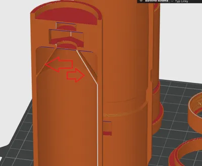
Part Bat B has modeled supports that need to be removed.


If you are making two swords and you want to join them, you also need to remove three plugs and insert an M10 nut into the hole.

Glue together parts "Ring A", "Ring B", and "Ring C".
Glue the part "body on off" and "inside on off". Be careful, the opening for the switch must be concealed!
Glue the part "body mode" and "inside mode". Be careful, the opening for the switch must be concealed!
The bottom part of the handle consists of multiple pieces that need to be glued together. Remove the supports from part "Bat B", or remove the plugs if you want to join 2 swords. If you want to join 2 swords, you need to insert an M10 nut into the bottom part. (Ideally, glue the nut - it will improve the strength of the part). Then glue parts "Bat B" and "Bat A" together. Then gradually slide on rings "A", "B", "C", "D", "E", and "End". These rings will reinforce the handle and create the handle design.
After gluing, you will have 4 parts that will be joined by screws. Be careful, the threads may be a bit tight, but you just need to screw and unscrew them a few times to wear them down a bit...
To join two swords into one, you need to print the "joining part". I print it in two pieces (no supports needed). Screw an M10 threaded rod about 6-7 cm long into the joining part. It may be difficult, but it will work. (You can slightly enlarge the hole with a drill - depending on the printer settings and its tolerances). This joining part will be connected to the handle with the embedded M10 nut. If you did not insert the nut into the handle at the beginning, it will not be possible to join the swords.
Electronics
I bought the components from local online shops, but you can definitely find them on AliExpress or in your local online stores.
Here's what I used:
Arduino Pro Mini https://techfun.sk/produkt/arduino-pro-mini-precizny-klon/
Gyroskop PMU6050 https://techfun.sk/produkt/gyroskop-akcelerometer-mpu6050/
MP3 Player: https://techfun.sk/produkt/mp3-prehravac-mini-df-player/
RGB led strip 2x1m: https://techfun.sk/produkt/led-rgb-pasik-ip30-30-60-144-led-1-2-5-metrov/
Polycarbonate tube: (outer diameter 30mm, inner diameter 26mm, length 200cm)
2x10kohm resistor for the color change buttons.
You will also need 1x switch for turning the sword power on and off. 2x buttons for changing the color and extending/retracting the sword. 1x speaker - I used speakers from an old laptop. 1x 18650 battery - I also took it from an old laptop. I also recommend a charger for 18650 batteries - I use IMAX. Additionally, some connectors, soldering iron, small screws, and a micro SD card. I used what I had at home...
The switches I used were salvaged from old PCs. They are 8x8x8 mm cubes, similar to these but larger. https://techfun.sk/produkt/tlacidlo-6-pin-dpdt-uzamykatelne/?attribute_pa_rozmery-tlacidla=7x7-mm Attention, you need to verify which two pins you will use. 2 pairs are connected before pressing the button, and 2 pairs are connected after pressing the button. Connect the middle pin and the outer pin...
Schema:

ATTENTION: The gyroscope PMU6050 in the diagram, and the one I had at home, had swapped VCC and GND! Check the polarity of all components!
I used 2x1m RGB LED strips with 144 LEDs per meter. I used a 1m long tube. Since I needed some space for cables, I cut off the last approximately 7 LEDs from the LED strips. If you use a different number of LEDs per meter (e.g., 60 LEDs/m), you need to adjust this number in the code. However, I found 144 LEDs/m to work best for me.
I connected the VCC, GND, and Data pins of both LED strips so that they ended in one connector.
I glued the LED strips together (you can use an aluminum profile for LED strips and stick the LEDs on both sides) and wrapped them in foam foil used for insulation under floating floors, which you can buy in hardware stores (1m2 = 2€). I then wrapped the cylinder with adhesive tape. This can be avoided if you buy a frosted tube instead of a clear one.
In the attachment, I am providing the complete code and sound files.
Put the contents of the "sounds" folder onto an SD card and insert the card into the DF Mp3 Player.
Upload the contents of the "libraries" folder to your Arduino libraries folder. This folder is usually located in C:\Users\admin\Documents\Arduino.
To upload the program to the Arduino Pro Mini, you will need an external programmer or another Arduino board through which you will program the Arduino Pro Mini. (Use Google 😊).
I had my own board made at https://jlcpcb.com/. I have a few left.


Comment & Rating (11)