
3000ma LiPo Battery Pack with
Print Profile(1)
Description
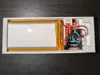
Portable 5V LiPo Power Bank Case (3000mAh with IP5306 & JST-PH Output)
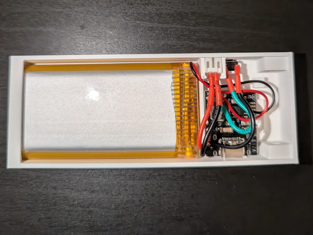
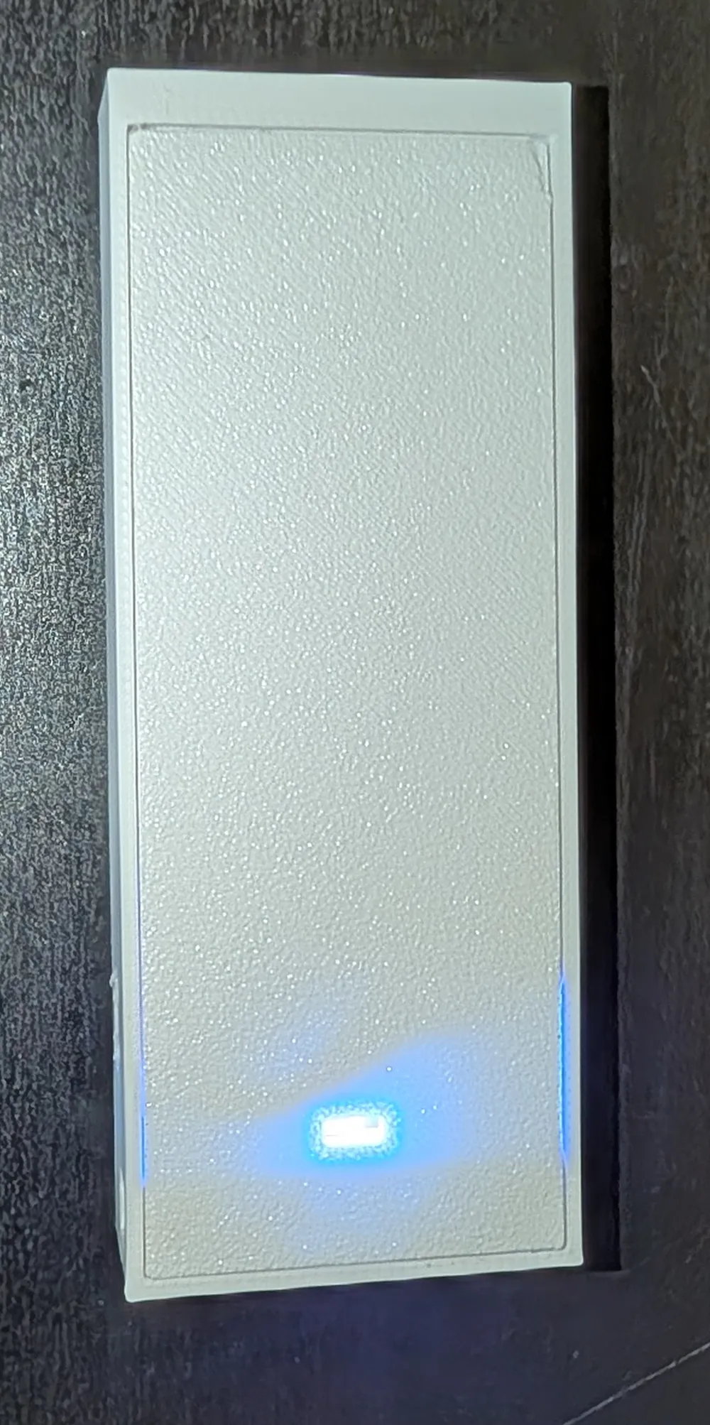
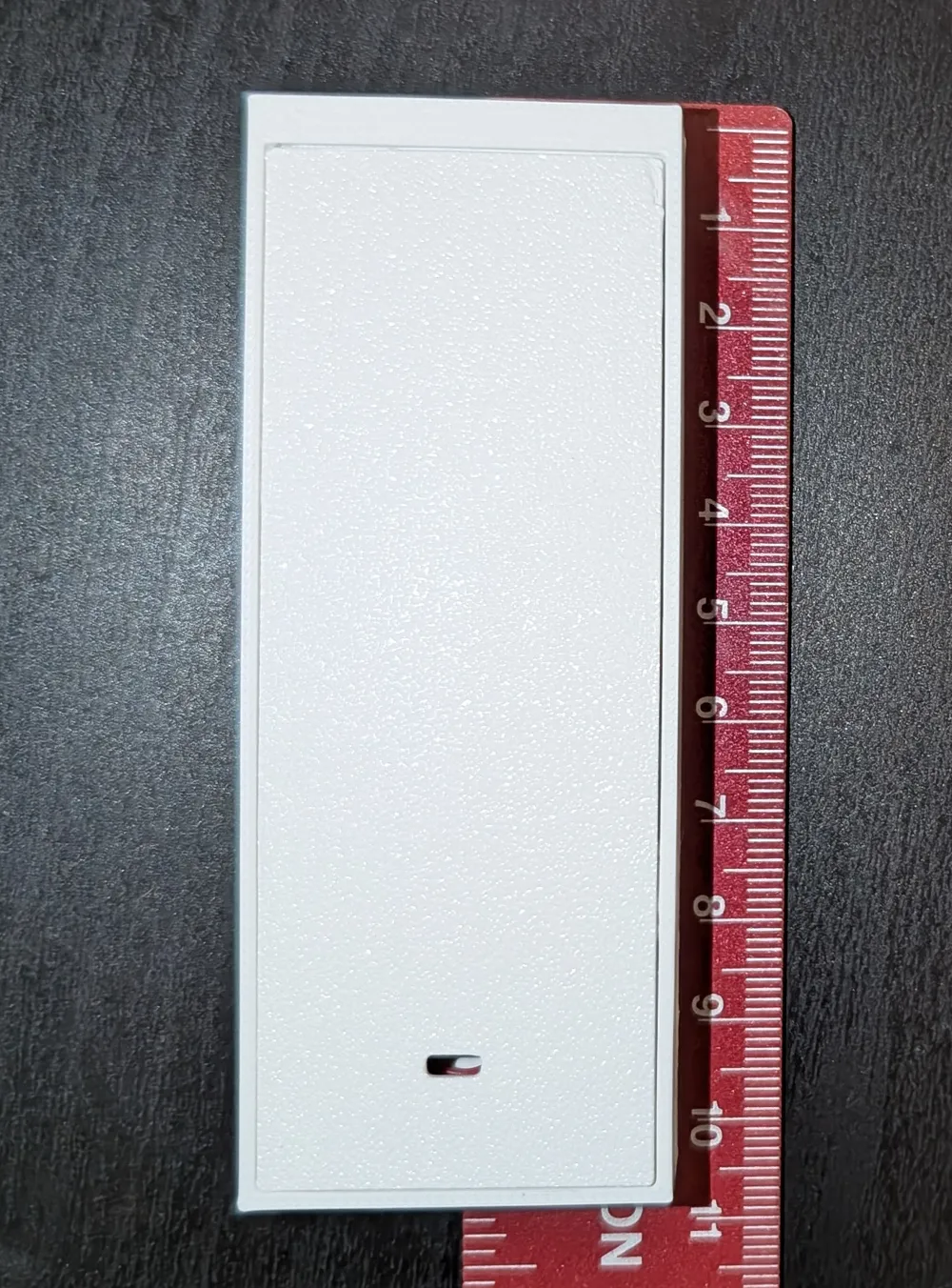
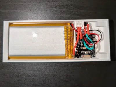
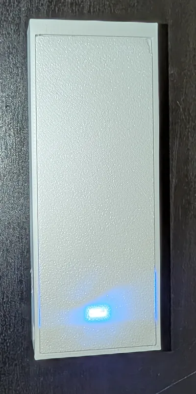
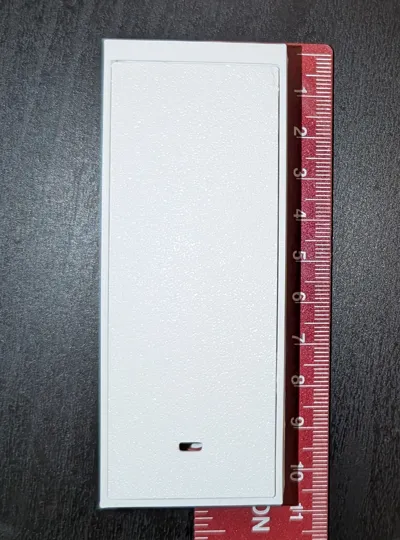
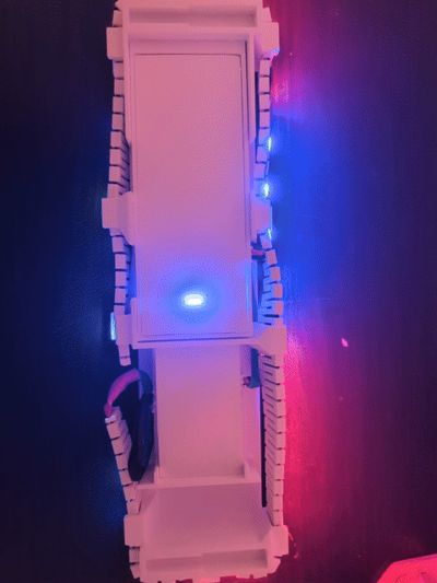
This is a compact, 3D-printed enclosure designed to house a portable power system for your DIY electronics and microcontrollers (like ESP32, Arduino, or Raspberry Pi Pico). It features an integrated charging/boost circuit, an accessible momentary power switch, and a secure JST-PH 2.0mm pitch output port to easily connect and swap different projects.
🚀 Features
- High Capacity: Tailored to fit a high-capacity 3000mAh 1S LiPo battery.
- Smart Charging & Boosting: Uses the IP5306 board for efficient Type-C charging and reliable 5V/2A power boost.
- Convenient Control: Features a dedicated cutout for a 6x6mm momentary tactile switch.
- Project-Ready Output: Built-in mount for a JST-PH 2.0mm pitch connector, making it incredibly easy to plug in your projects without loose wires.
- Compact Design: Minimizes footprint while cleanly organizing the internal components.
🛠️ Bill of Materials (BOM)
To build this project, you will need the following components:
- Power Module: IP5306 5V 2A Type-C Boost Converter Board
- Battery: 3.7V 3000mAh LiPo Battery (1S)
- Output Connector: JST PH 2.0mm Connector Kit
- Power Switch: 6x6mm Tactile Push Button Switch Kit (Use the 6x6x4.3mm button from this kit)
- Hardware: M3 Hex Socket Screw and Nut Assortment Kit] (Project uses M3 nuts and 10mm M3 screws)
⚠️ Important Safety Warning
❗LiPo Battery Caution: To connect this specific battery to the IP5306 board, you will need to cut the factory JST-1.25mm connector off and solder the leads directly to the board. NEVER cut both the positive (red) and negative (black) wires at the same time. Doing so will bridge your flush cutters/scissors, causing a dangerous direct short circuit. Cut, strip, and solder one wire completely before touching the other.
🔧 Assembly Brief
1. Prepare the Components: Solder the momentary switch and your JST-PH 2.0mm connector leads to the designated spots on the IP5306 board.
2. Wire the Battery: Carefully prep and solder the battery leads to the board's power inputs (adhering strictly to the safety warning above). Double-check your polarity!
3. Mount the Electronics: Slide the IP5306 board into its internal slots, aligning the Type-C port with the exterior cutout.
4. Install the Switch & Connector: Press-fit the 6x6x4.3mm tactile button and the JST-PH connector into their respective external housings.
5. Secure the Lid: Slip the M3 nuts into the dedicated capturing slots on the lid. Line the lid up with the base, and thread the 10mm M3 screws through the bottom to lock the case together.
License

You shall not share, sub-license, sell, rent, host, transfer, or distribute in any way the digital or 3D printed versions of this object, nor any other derivative work of this object in its digital or physical format (including, but not limited to, publishing derivative works outside the Makerworld platform or hosting on other digital platforms). The objects may not be used without permission in any way whatsoever in which you charge money or collect fees. Subject to the above restrictions, derivative works may be published only within the Makerworld platform, and all such derivative works must be licensed under the same SDFL‑C license, without modification or additional terms. You may download the digital versions of this object, 3D print it, and display images, videos, or usage demonstrations of 3D printed versions of the object on personal social media platforms or Makerworld official channels, provided that no digital versions of the object are shared or distributed.


Comment & Rating (0)