
Trackside Factory (TSM#03) for Z & N-Scale
Print Profile(6)





Description
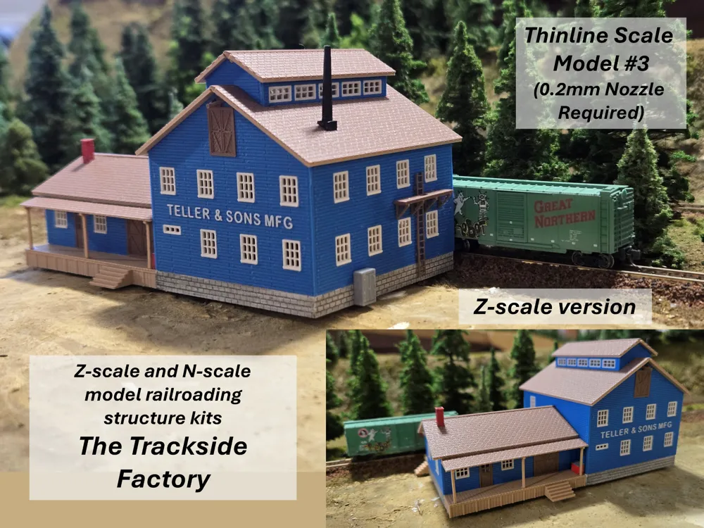
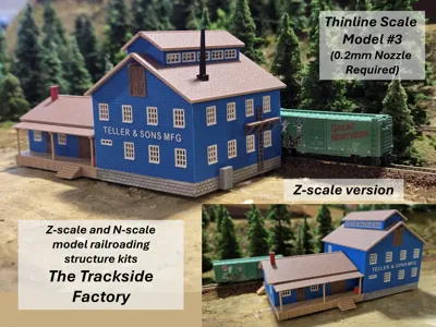
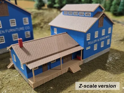
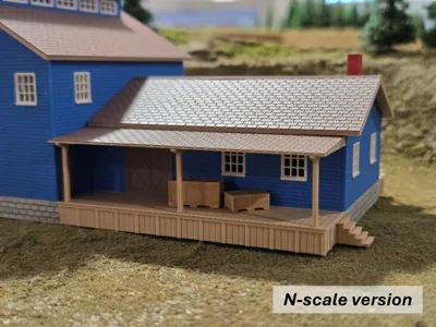
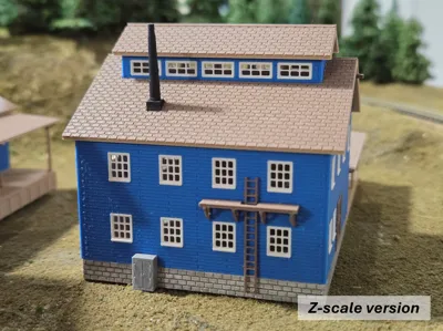
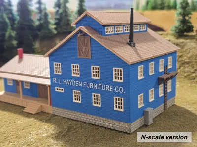
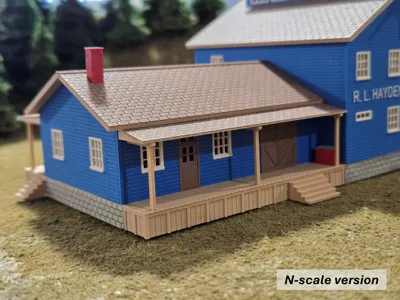
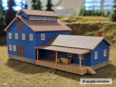
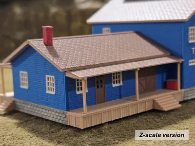
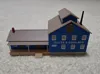
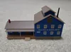
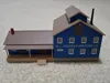
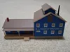
This model is the third in a series of “Thinline Scale Model” structure kits for Z-scale and N-scale model railroading.
[Note: the HO-scale version of this kit is available here: https://makerworld.com/en/models/3036818-the-trackside-factory-ho-scale-edition#profileId-3414170.]
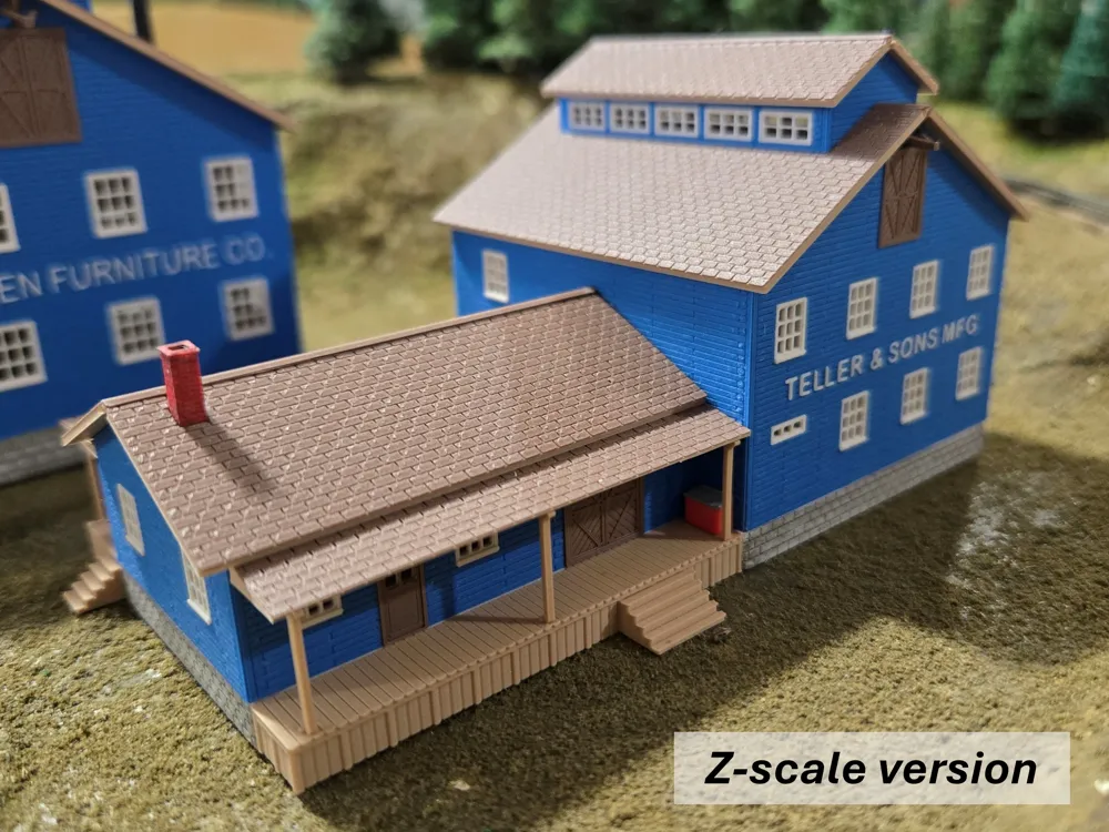
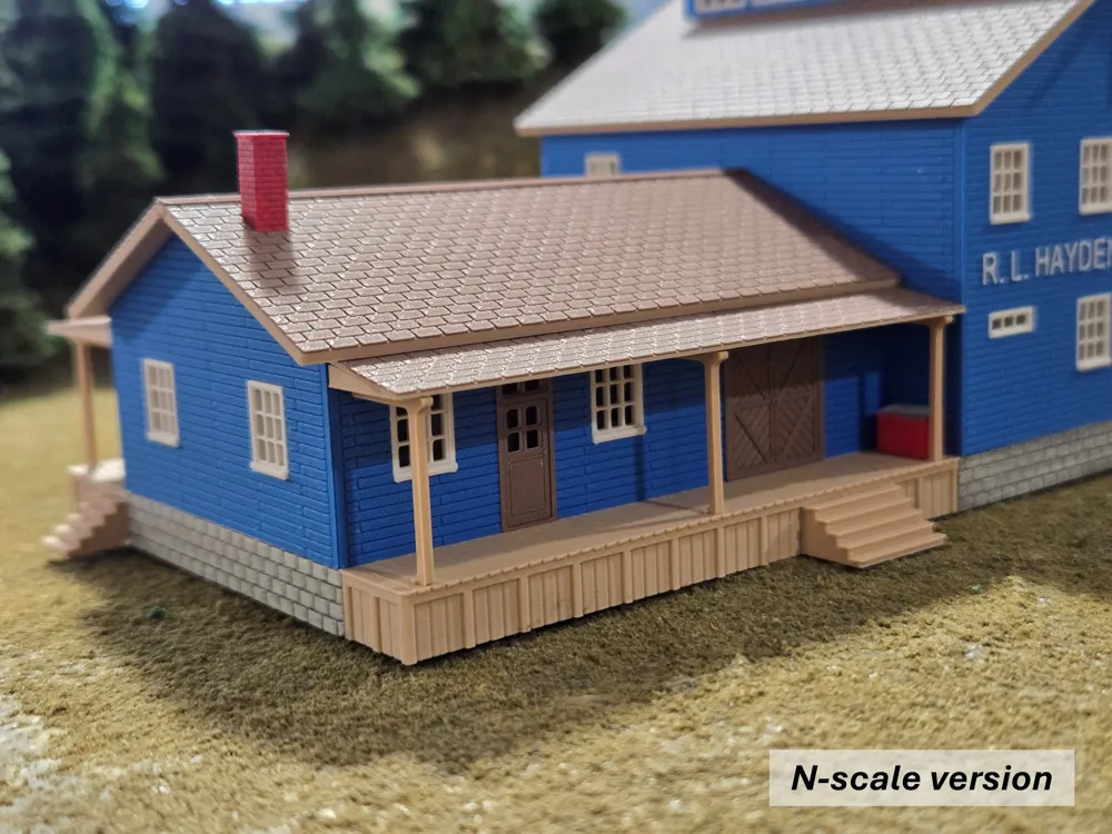
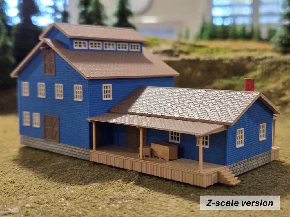
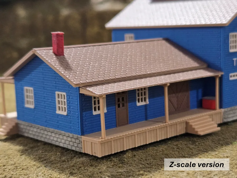
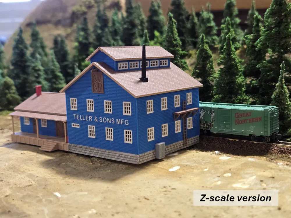
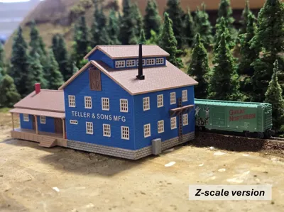
The Trackside Factory (TSM#03) - This structure kit is for a factory that could be located off of a track siding. For my layout, this factory will be receiving lumber from a lumber mill down the line and producing wood-based products, such as furniture, for shipping out to market via the railroad. To see other kits in this series, including HO-scale versions, please visit my collection page: https://makerworld.com/en/collections/15297762-model-train-projects.
| I designed this model in SolidWorks inspired by an original design by a former member of our Z-scale modeling club - he did market a laser-cut wood kit for a short while (as fannocreekdesigns) but alas those kits are no longer available so he graciously gave me permission to craft my model as a likeness of his. Given my model is for 3d-printing, I've completely re-engineered the way that the kit is made and assembled, and I've made other design changes based on how some interior aspects of the factory would change some of the exterior appearance. And, after many failed attempts to recreate an exposed support structure under the trackside dock and front deck that would print reliably in one piece, I chose to enclose the underside of both dock and deck. | 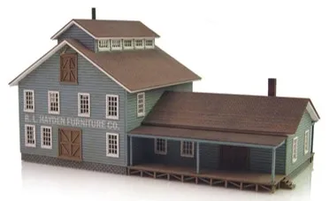 |
Important Note: Before proceeding to print and build these kits, please note the following special requirements needed to produce good results. Also, please read through the entire description to understand all of the assembly steps required.
- For printing, a 0.2mm nozzle and a clean smooth build plate is required - this model is specifically designed for using a 0.08mm layer layer height and a 0.22mm line width for the Z-scale model. The N-scale model uses a 0.11mm layer height and a 0.22mm line width.
- This kit includes both two-color and three-color prints - an AMS is required.
- Supplied needed: fast setting (5-10 seconds) CA adhesive with a toothpick or tool for spreading along mating edges; and a selection of acrylic paints / brushes for painting the model (if desired).
- Tools needed: a good bed scraper tool for removing some of parts from the smooth build plate - I found the bed scraping blade supplied with the printers by Bambu Lab to work well for this purpose (most beneficial was its thin sharp blade for lifting very thin prints).
The Print Profiles - Three profiles each are available for each model train scale (Z or N) of this structure kit, the profiles generally differ by single (P1S, A1, H2S, etc.) and dual-nozzle (H2D and H2C) printers, and also an A1 Mini-specific profile. Please note that all of the profiles include a number of parameter changes from the standard print profiles that probably should not be tampered with if you want good results. One of the more important profile variances is that I've significantly slowed down the nozzle speed, travel speed and acceleration to help assure the best result printing the detail features of these models - I've specifically supplied separate profiles based on direct-drive nozzle count because changing the printer of a single-nozzle profile to a dual-nozzle printer (and vice versa) may cause the speed settings to be lost in the profile. I highly recommend that you use the appropriate single or dual-nozzle profile matching your printer capability, and I include the X2D with the single-nozzle printers since its auxiliary nozzle is not recommended for use with a 0.2mm nozzle.
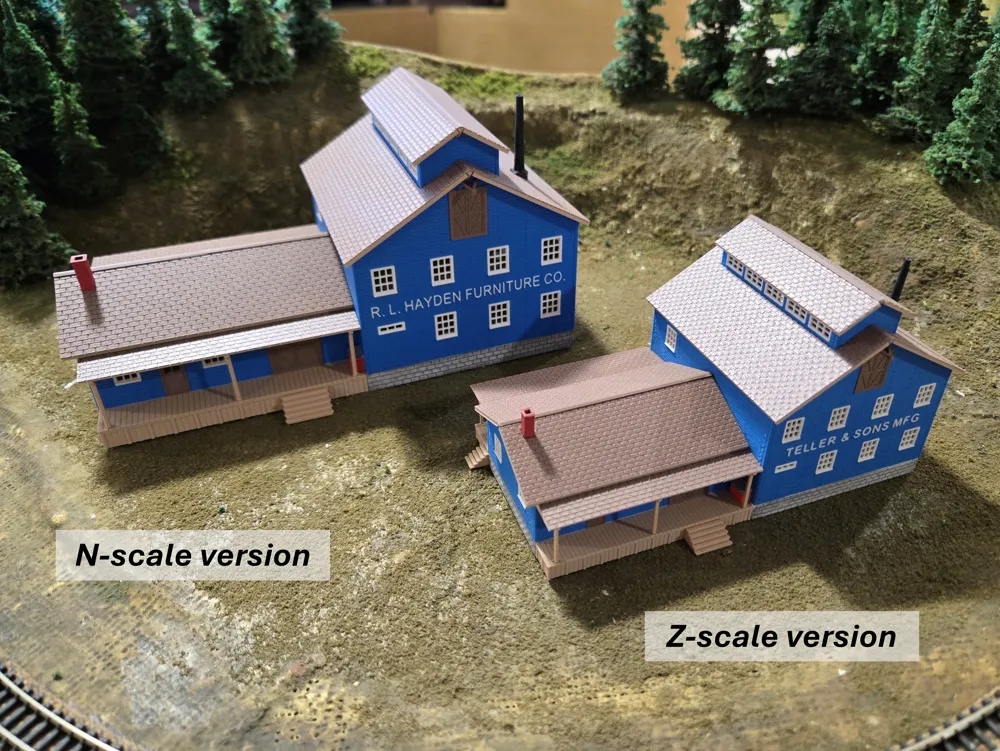
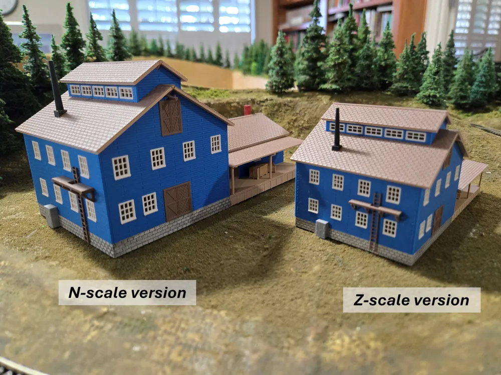
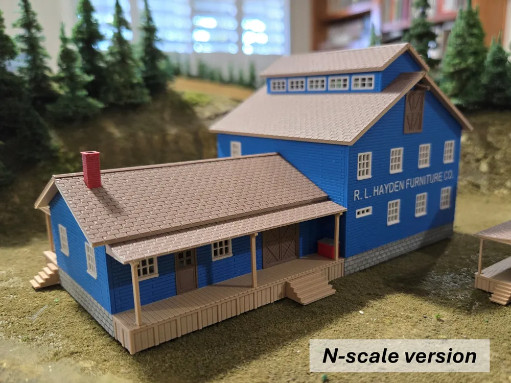
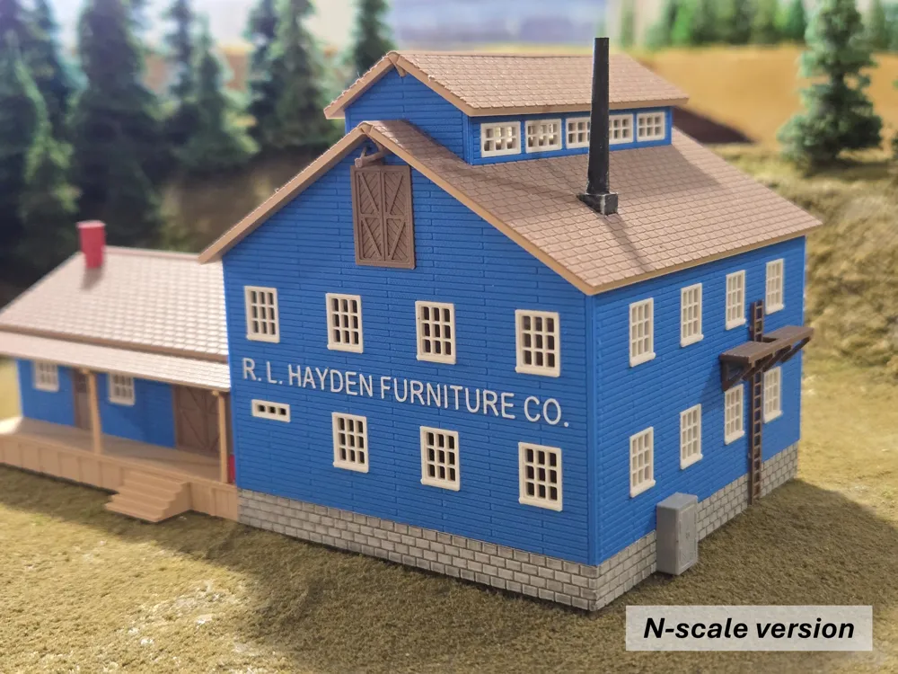
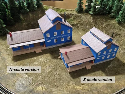
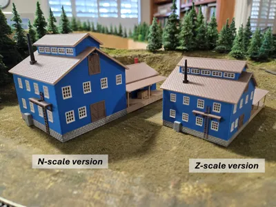
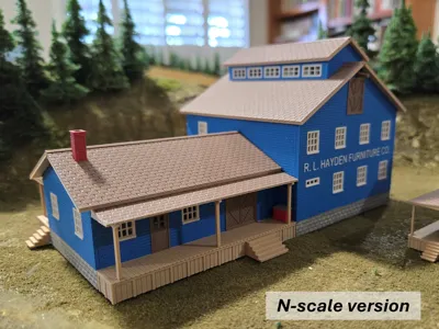
Important note regarding the factory name: The original laser-cut wood kit included decals for naming the factory, a choice of either “R. L. HAYDEN FURNITURE CO.” or “TELLER & SONS MFG”, the latter one being the one I'm planning to use on my Z-scale layout. For the Z-scale profiles, I've only included the “TELLER & SONS MFG” choice as the other name is too long to print cleanly. For the N-scale profiles, I've included both naming options with the “R. L. HAYDEN FURNITURE CO.” as the default choice - if you prefer “TELLER & SONS MFG” on your N-scale model, find the build plate where the wall with the name appears and deselect the named wall you don't want and select the named wall that you do want. Make sure that only one of these walls are selected for printing … if both are selected, Bambu Studio should complain and you will need to deselect one to proceed; if none are selected, you will be missing a wall in the print so make that one is selected. If you have questions about any of this, please feel free to reach out to me.
- One final note … you can optionally remove the name from the wall by deleting the text element, or you can attempt to change the name to something you prefer but please note that you should take care to recenter, left to right, the text on the wall after you edit the name. Also note that the text tool when used on a textured surface such as these walls can be a bit finicky with sometimes distorting the placement of individual characters so you might have to mess around with it a bit to get it to behave. I've taken some care to make sure that the text fits nicely when positioned vertically across the siding boards. And finally, most of the text fonts available will not print well at these scales which is why I've focused on the two sans-serif fonts used in the profile.
Important note before removing the parts from the build plate: After printing your model, please only remove the parts after the build plate has completely cooled to room temperature. Many of the model parts are extremely thin (e.g., between 0.64 and 0.8mm in Z-scale) and can be easily damaged. Some of the parts can't be removed simply by flexing the build plate so with the build plate removed from the printer and set firmly on a work surface, use a sharp bed scraper tool to very carefully work up and lift each individual part by working slowly around the edges of the part. When removing some of the smaller parts, such as the L-shaped awning supports, you may want to place your hand over to capture them as they will tend to fly off once released from the plate.
Choosing Filaments - In my profiles, I've chosen to use Bambu Lab PLA Matte filaments as I prefer the surface finish over PLA Basic. With the model based on four colors as set in the profiles, all of the major elements of the model could be left as printed but there are a small number of details that I recommend be painted to help finish the model (see below for painting recommendations). I've tried to minimize the number of color changes needed on each build plate in the profiles to keep purge waste as low as possible.
=== ASSEMBLY INSTRUCTIONS ===
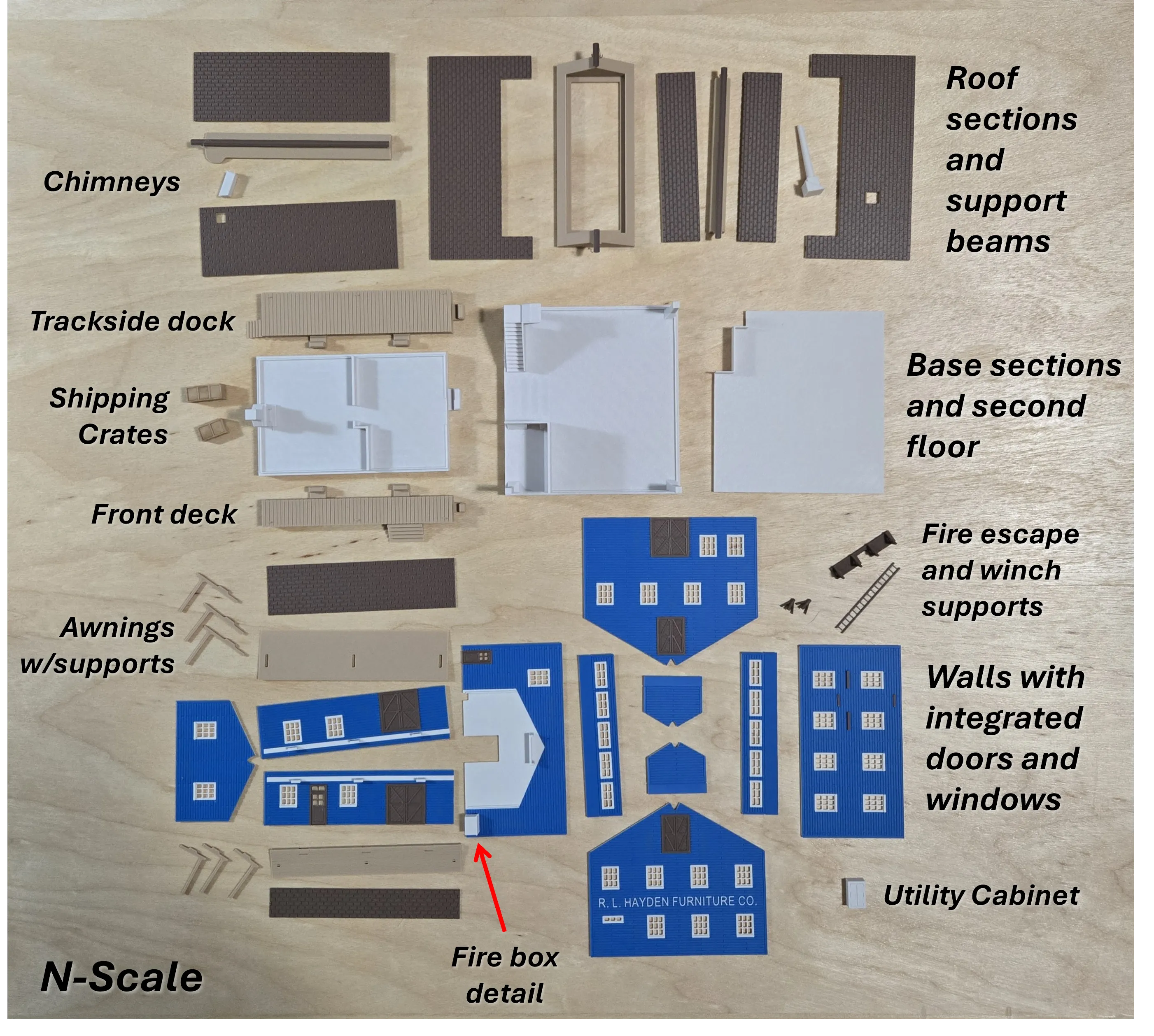
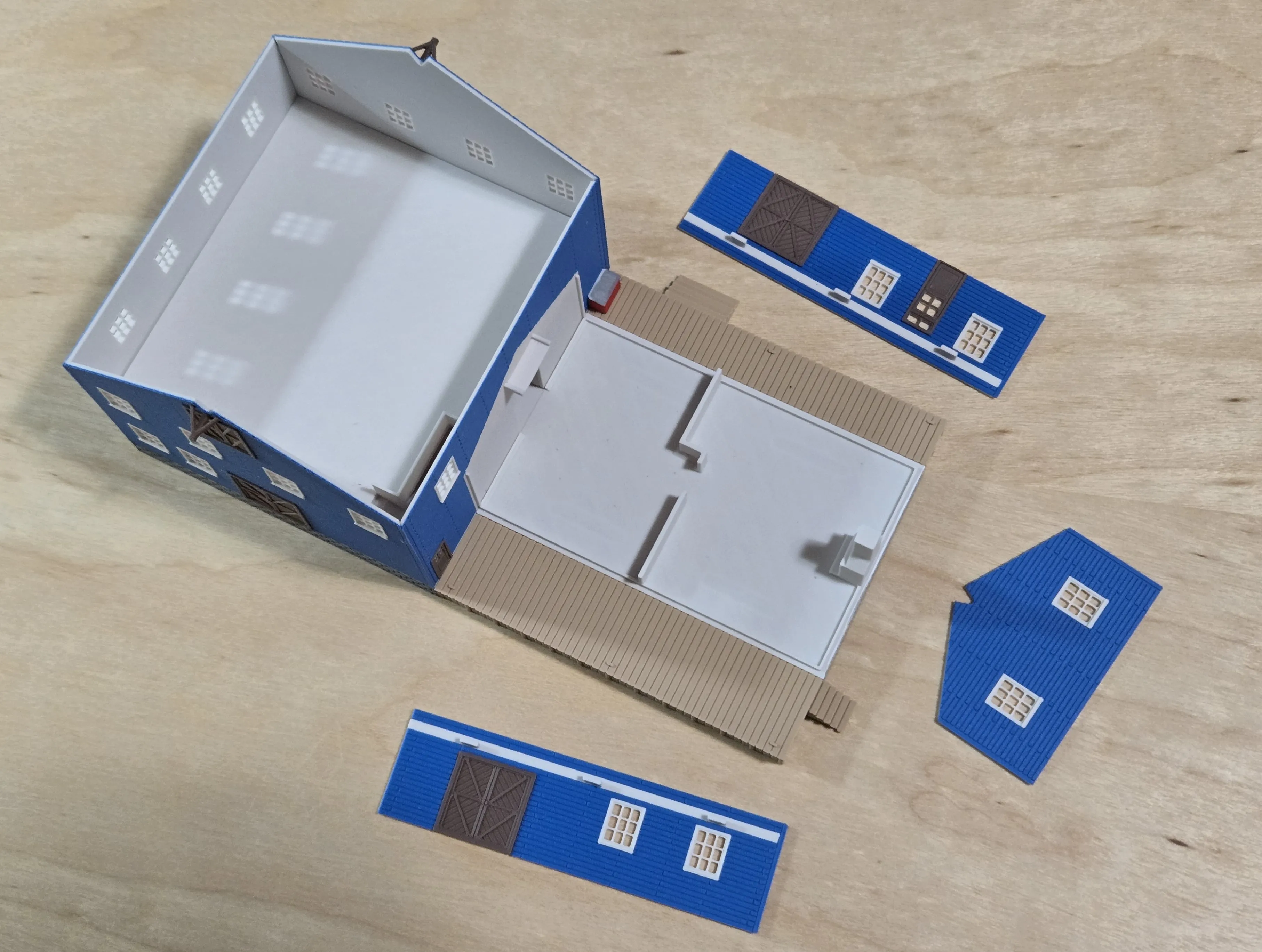
This diagram provides a general overview of the kit parts. The Z-scale and N-scale kits have the same set of parts - in terms of design, only the two small winch supports differ between the kits as the detail of the N-scale supports could not be reliably replicated in Z-scale. While these instructions are illustrated with pictures of the N-scale kit, the instructions are the same for the Z-scale kit.
=== Painting and Window Glazing Recommendations ===
At a minimum, I would suggest adding some diluted color washes to give a more weathered look to the structure. Before assembling the kits in the photos, I choose to paint the lower masonry block surfaces of the two white bases to help bring out the detail. I first coated the masonry surfaces with a white acrylic gesso and after that dried thoroughly, I worked it over with a thinned coat of ‘tarnished’ black, the gesso helps to create a more receptive surface for the paint on the plastic.
- For those interested, here is an Amazon link to the Micro-Mark Acrylic paints I've used on my models: https://a.co/d/0fMC2PB2.
There are a number of details in this kit that should be painted prior to assembly. This include the two chimneys, the utility cabinet, the shipping crates, and the firebox as seem in the following photo. The firebox is an integrated feature of the middle wall and it takes a bit of extra care in painting it without getting paint on the wall siding (blue) - note that I chose to paint the lid in gray with the rest of the box in red. For the crates, I only chose to dirty them up a bit to help differentiate them from the dock color.
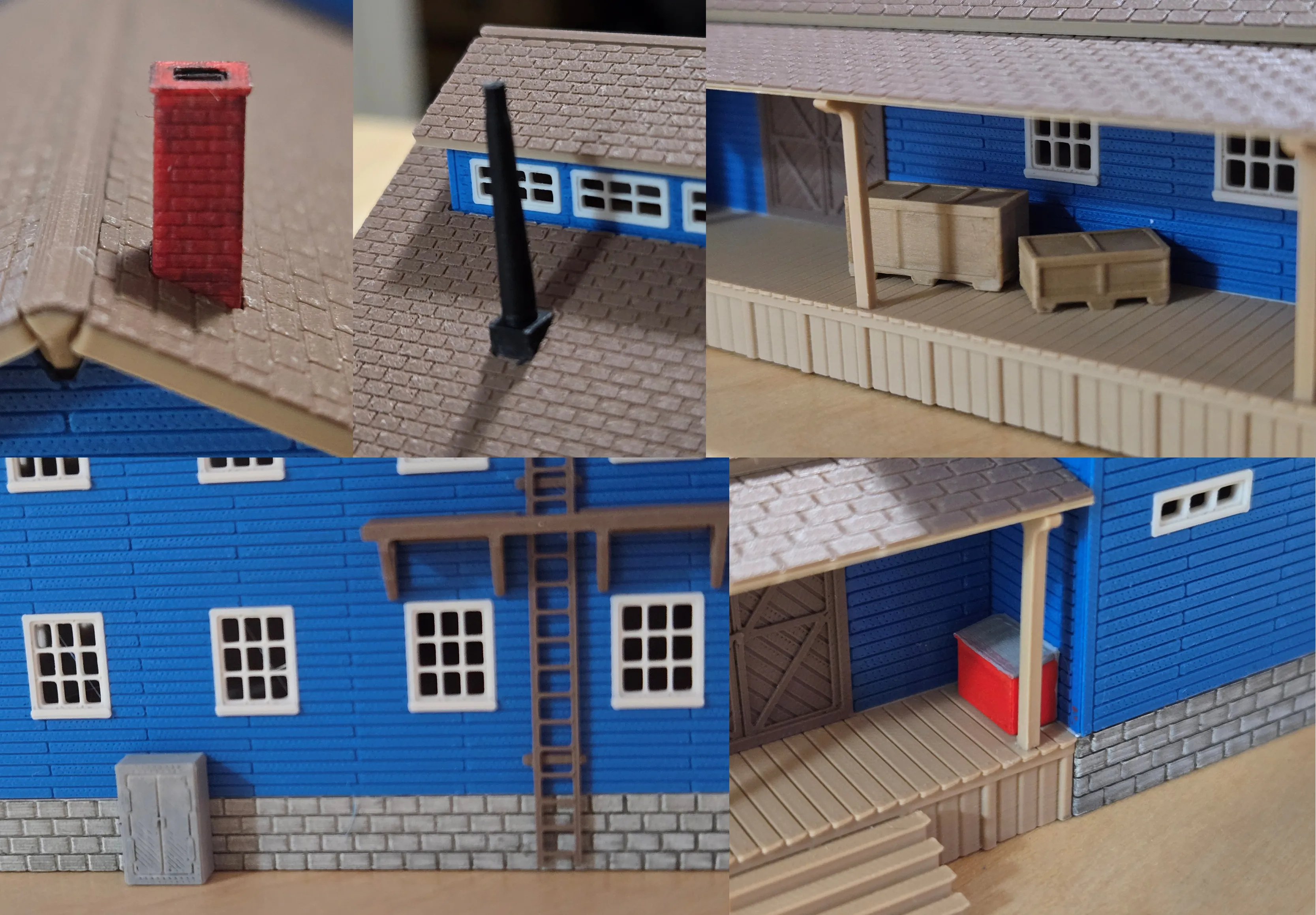
Note: If you choose to change the filament colors to either reduce the number of filaments or simply to picking more neutral colors with a plan of painting the model, you should consider painting individual parts prior to assembly although adding weathering detail is often done with the overall model built up. Using some paint color washes can help enhance the details while also making the building not appear as it was just build yesterday :-).
If you want to add window glazing (simulated window glass), I would suggest that being done either before attaching the walls to the base, or at least right after attaching the walls to the base - going beyond those steps in the assembly process will make it difficult to adding glazing. You also need to consider that if you are painting the model, care must be taken to not get paint on your window glazing so the painting versus glazing order becomes important.
- I'm still messing around with different techniques for glazing 3d-printed models … either using a clear film/plastic material or something like this clear adhesive by Microscale Industries (https://a.co/d/0gy3e33L) that can also be used to form small windows on models (this stuff can be a bit tricky to get it to work right but I've successfully used similar, unfortunately discontinued by Micro-Mark, products in the past.
=== Starting with some sub-assemblies ===
There are a number of sub-assemblies to complete prior to starting the general assembly of the kit. It is recommended that before applying adhesive, you study all of the photos closely to see how parts are supposed to fit once assembled. Once each is completed, set it aside until needed in the general assembly.
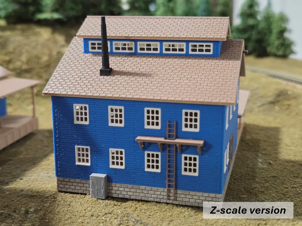
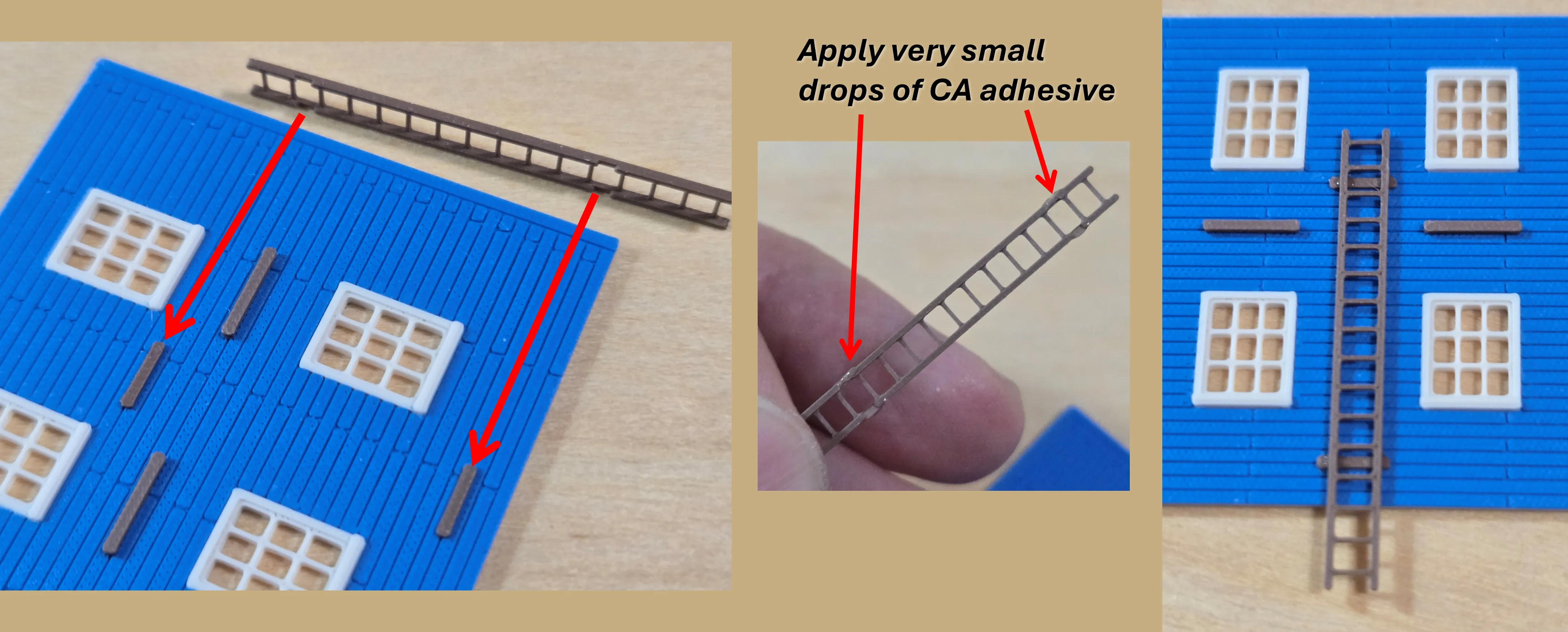
The Fire Escape
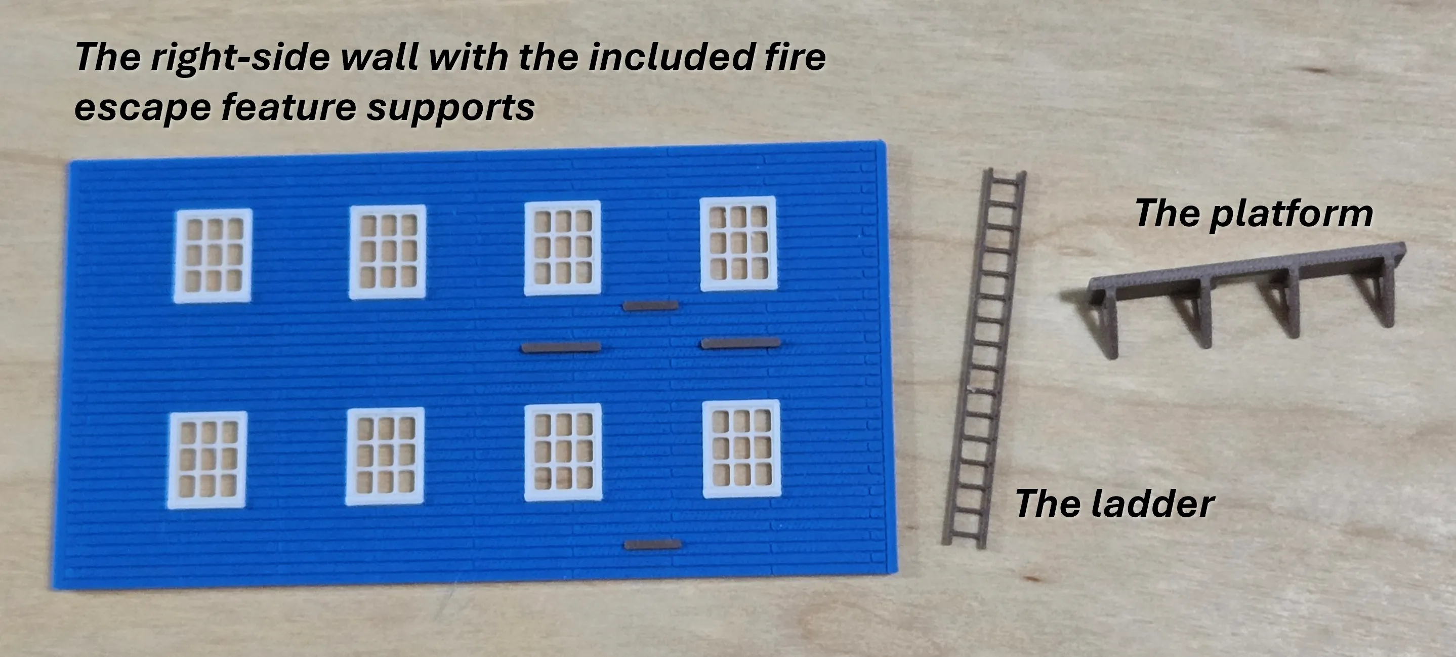
Note the alignment of the underside notches of the ladder to the support features of the wall - make sure to get the ladder in the proper orientation with the shorter piece of the ladder above the top notch and the longer piece of the ladder below the bottom notch (and extending below the wall once attached. Also take care to center the latter, left to right, on the provided supports. This can be a rather delicate job and using some tweezers might be helpful.
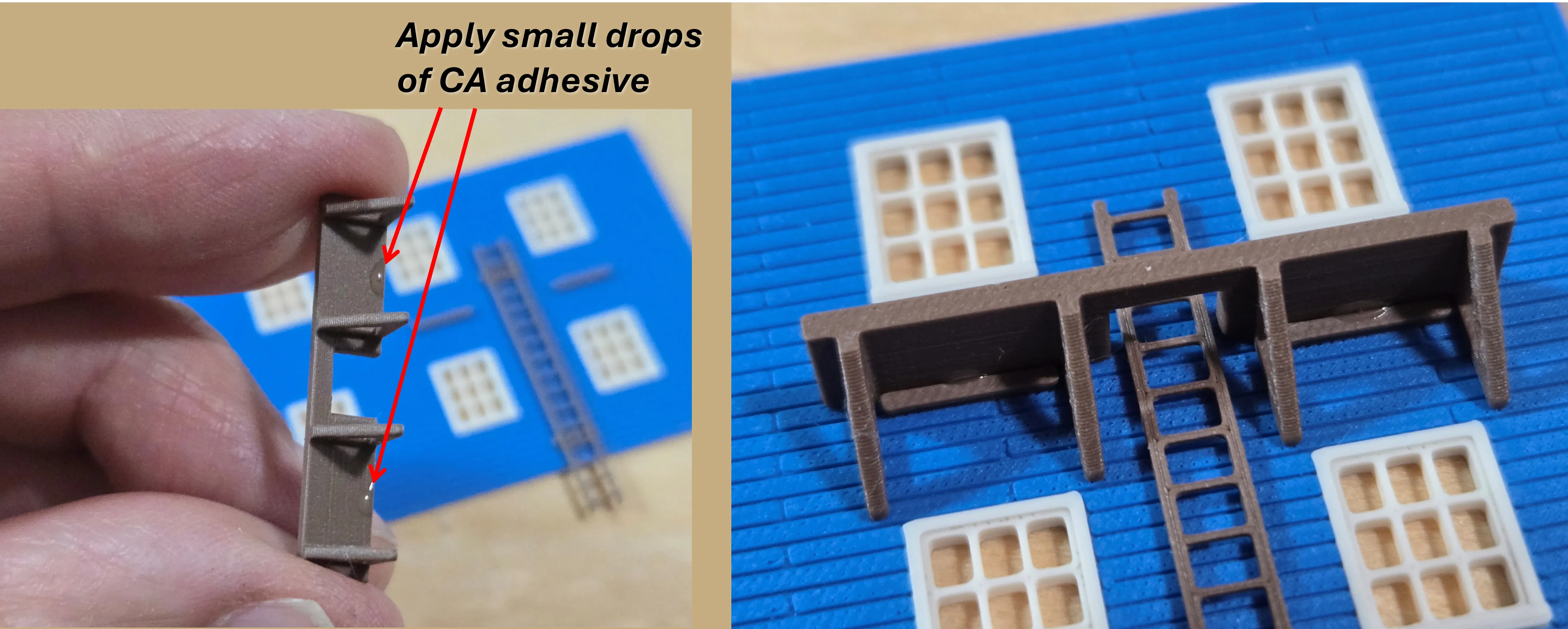
Note the alignment of the escape platform with the two provided wall supports centered beween the platform leg structures.
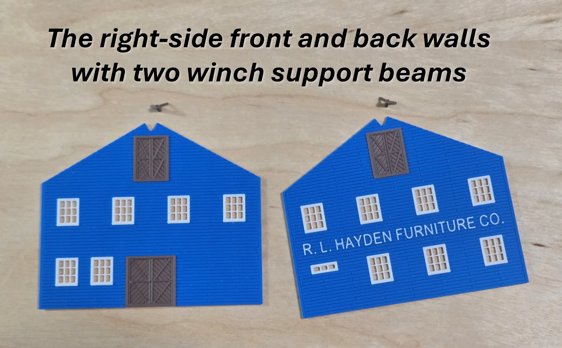
The Winch Support Beams
The winch supports are two small parts that look somewhat like mini-tripods.
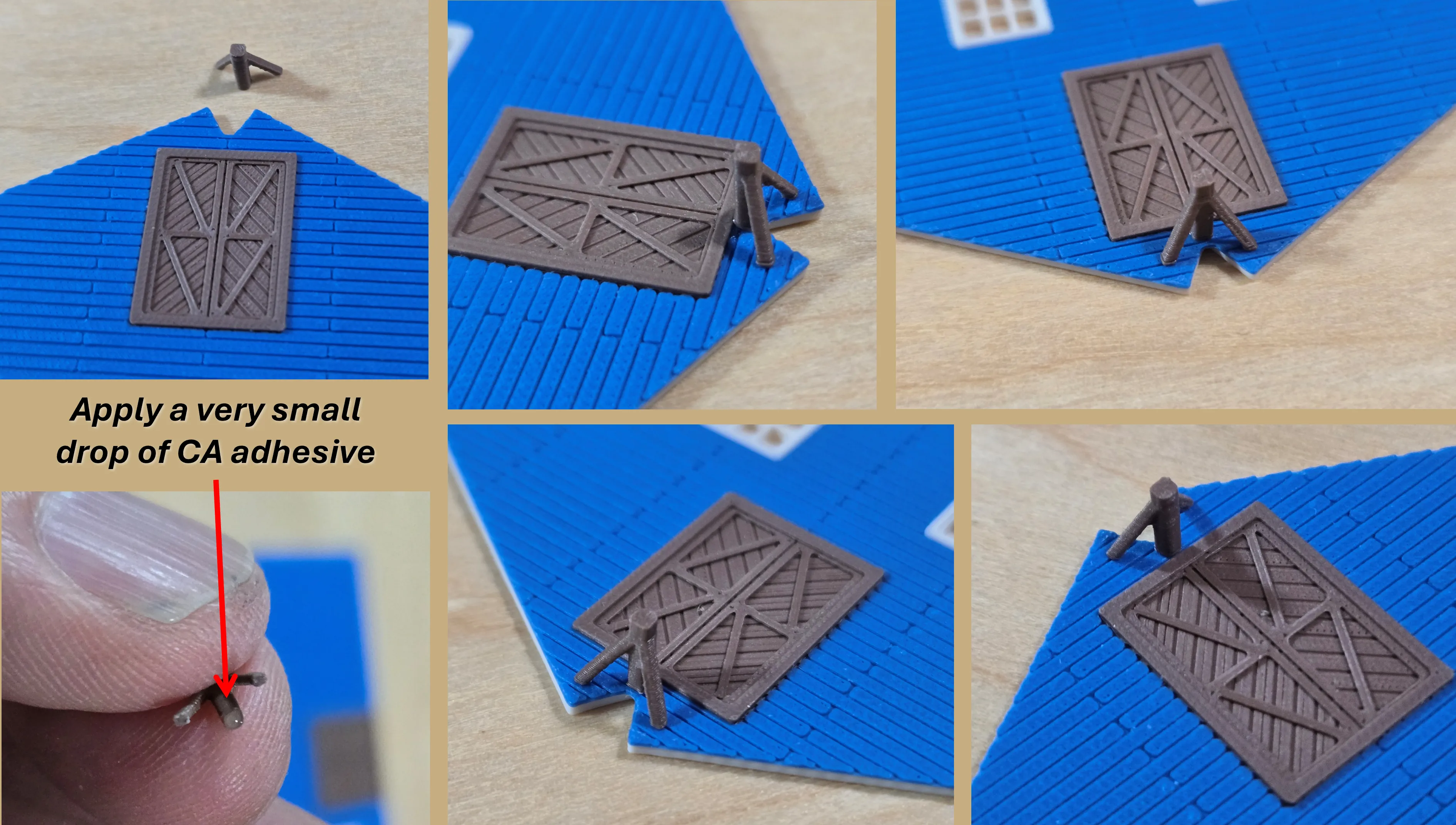
Note the alignment of the winch support relative to the top of the door and the notch in the wall.
The awning platforms with supports
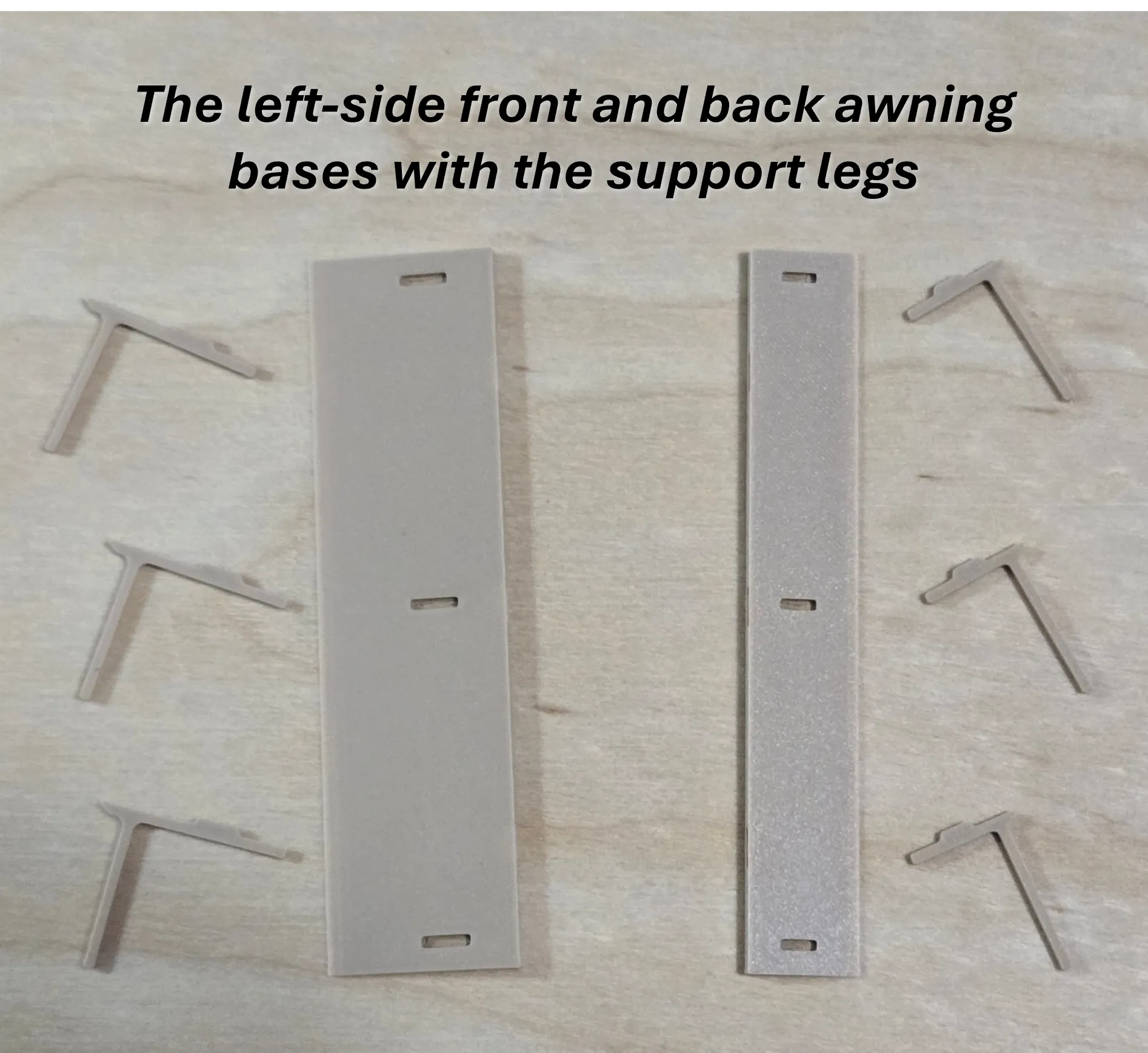
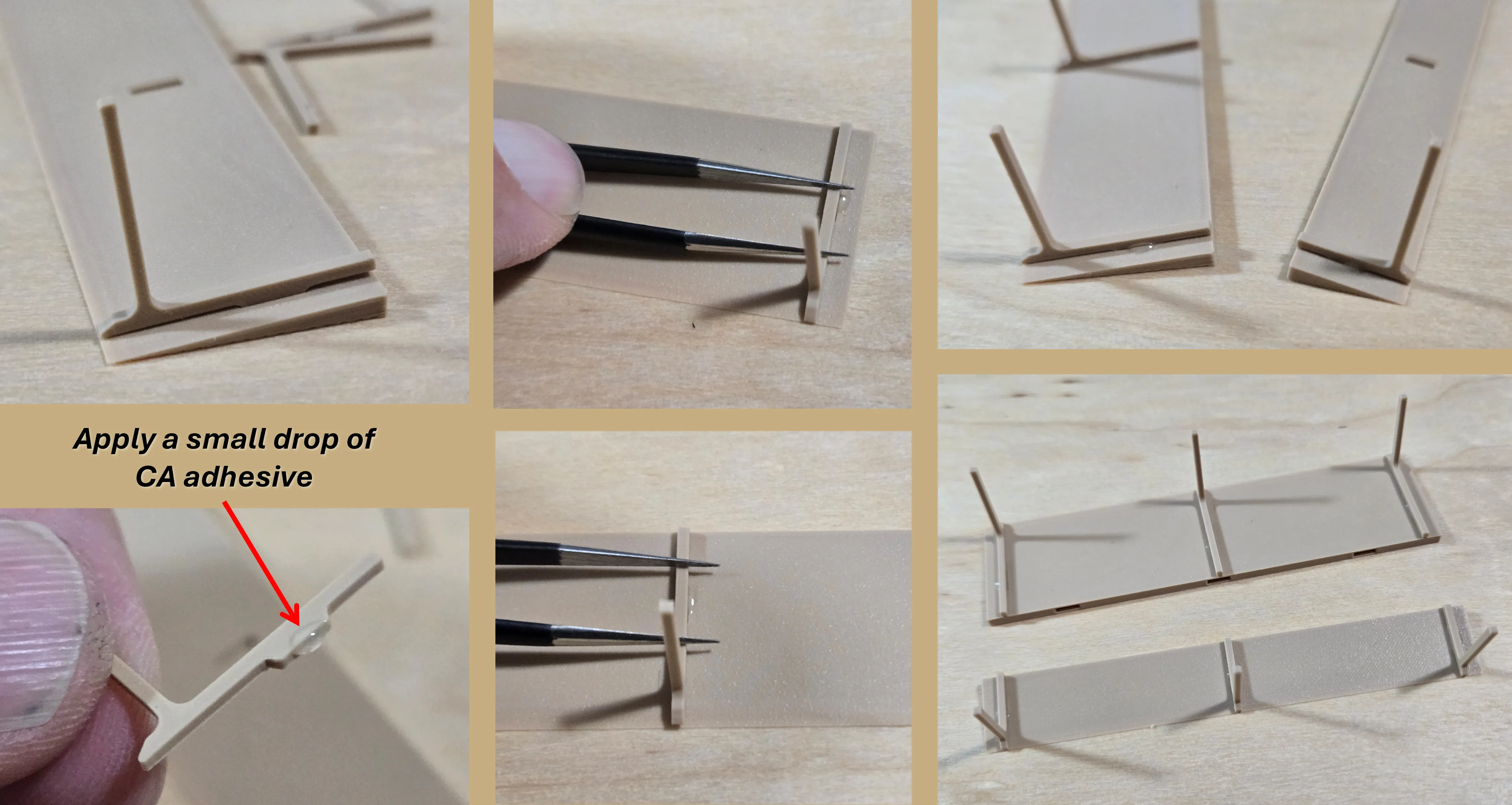
Note that the support legs have bumps that fit into the underside slots of the awning bases. Also note that the leg of the support is positioned closest to the thinner edge of the awning base. Key to this sub-assembly is to make sure that the supports sit flush against the surface of the base with the leg standing straight up, left to right, from the base. The larger awning platform is for the trackside dock and the smaller one is for the front deck.
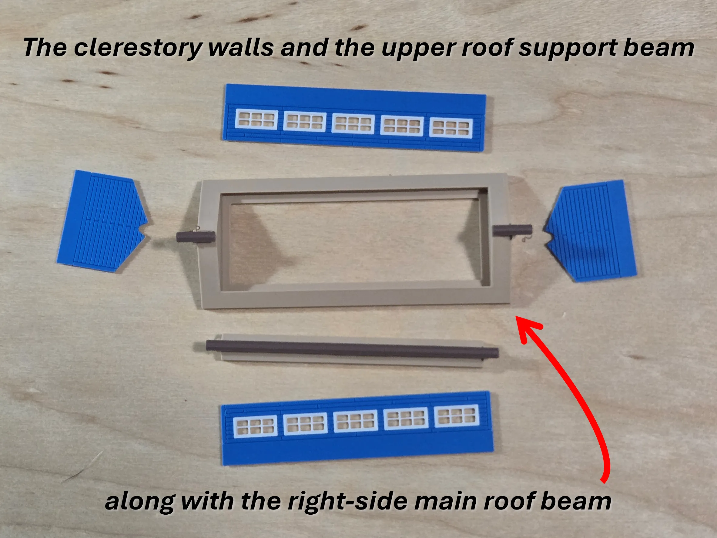
The clerestory
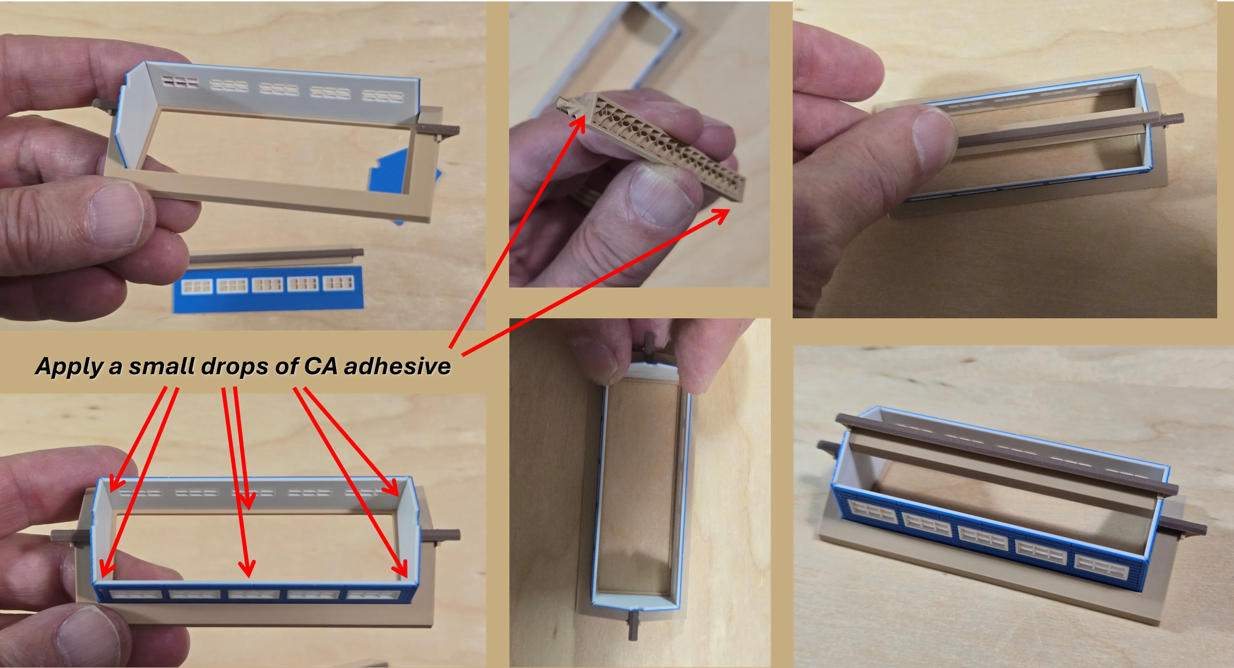
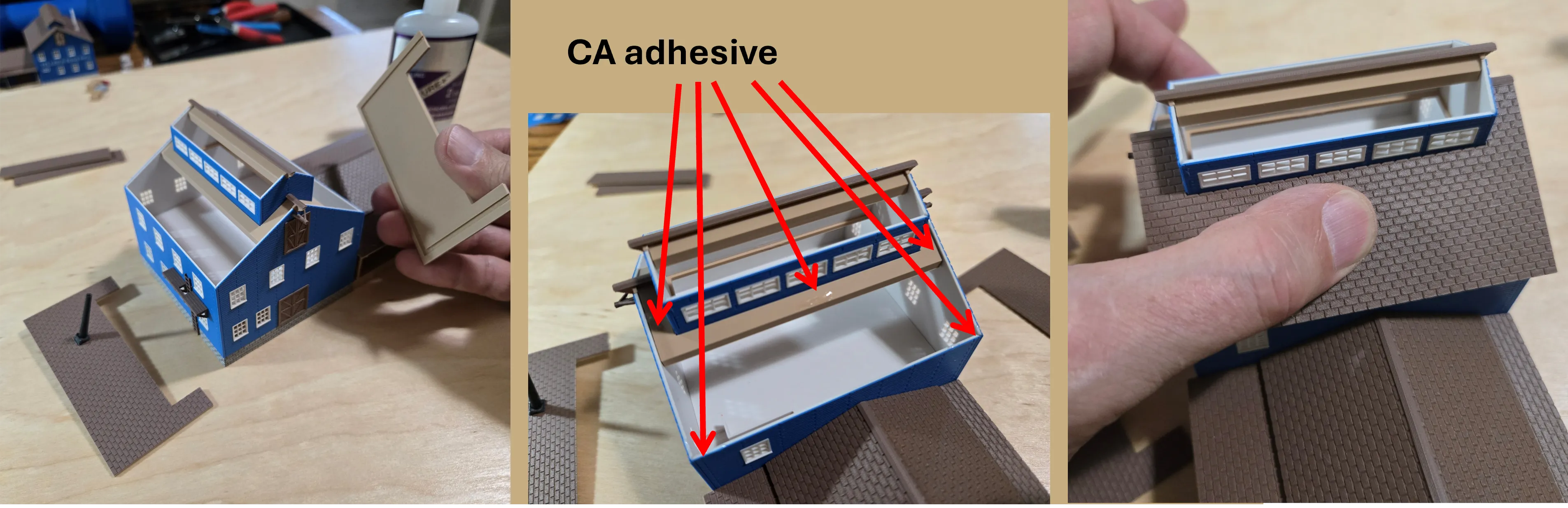
Note that the four walls fit well within the inside cavity of the main roof beam base. Once they are in position with all of the wall edges lined up and with the walls firmly seated down within the cavity, add the adhesive drops where the walls meet and with a couple more at the base on the longer walls down where they meet the base, and hold everything in position, making sure not to disrupt that the wall edges appear properly aligned with no obvious gaps. The upper beam can then be added with adhesive on the small flat surfaces of the beam to glue to the inside of the end walls when set into the alignment gaps.
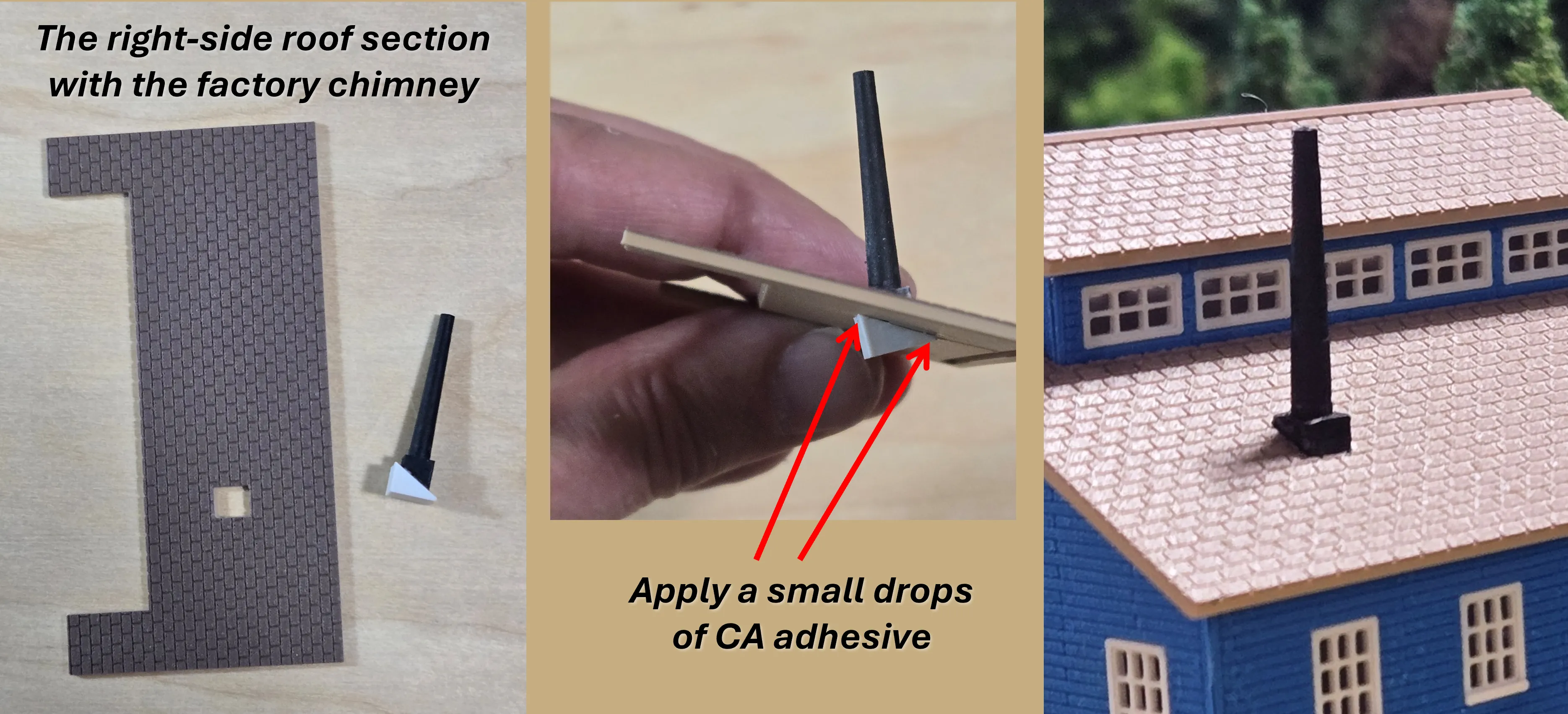
The right-side chimney
Note that the chimney needs to be inserted from the underside of the roof section and oriented with the thicker side of the chimney wedge base positioned toward the large gap side of the roof. Once you have the chimney firmly seated flush to the underside of the roof, apply some adhesive to hold it in place. The chimney wedged base serves to orient the chimney vertical once the roof is installed on the model.
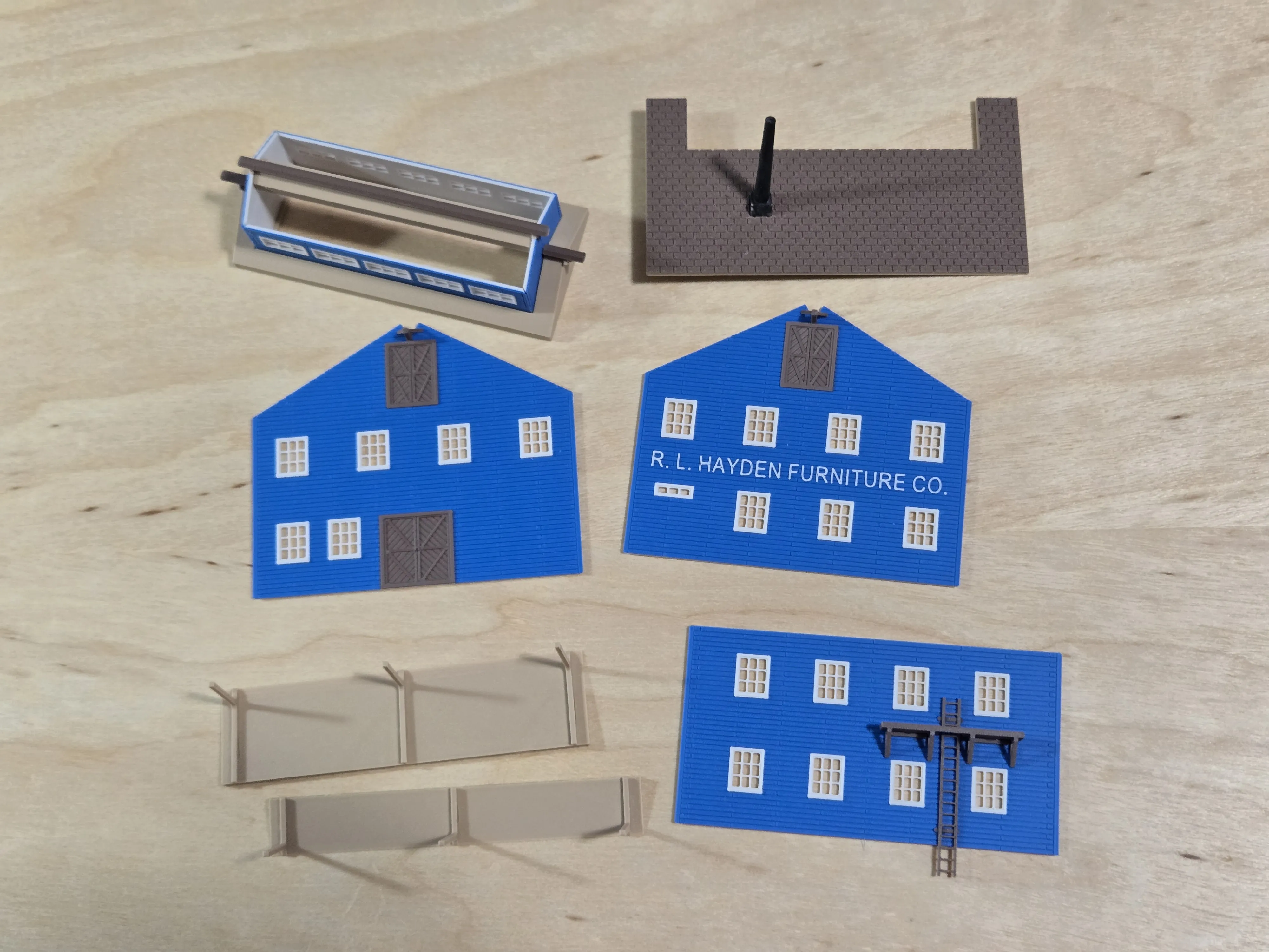
Now you should have the following sub-assemblies ready for use when starting the general assembly of the factory.
=== Assembling the factory ===
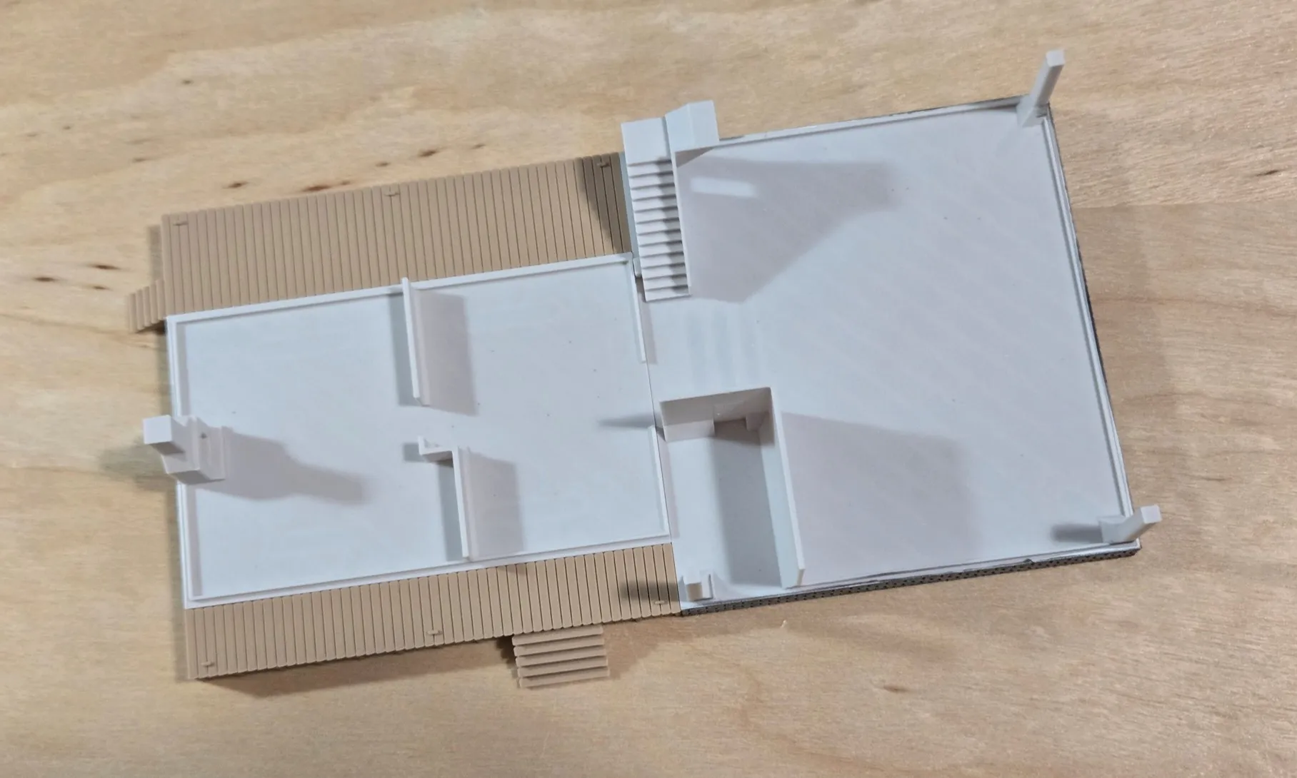
The base
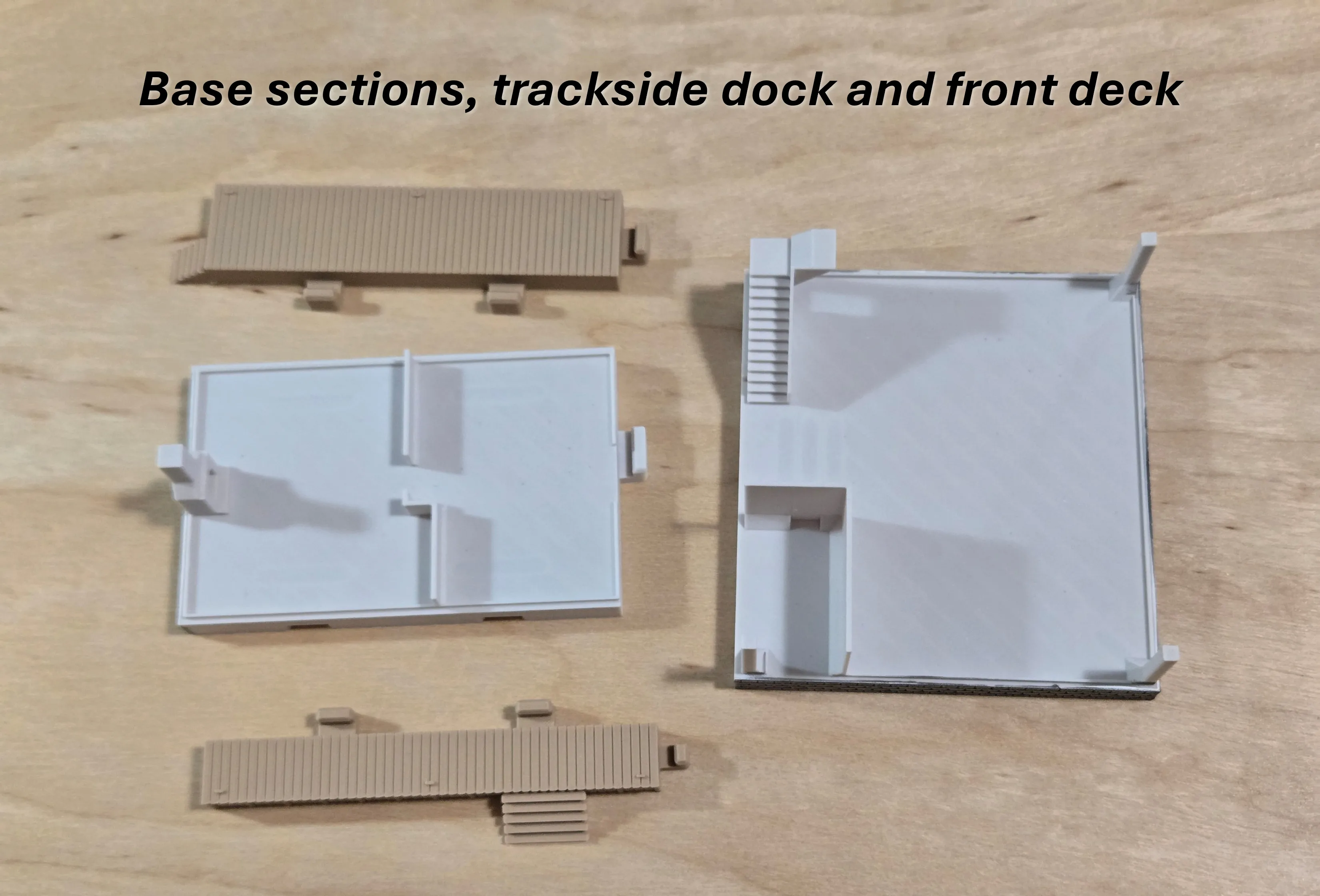
Each of the interlocking tabs on the left-side base, the trackside dock and the front deck have corresponding receiving slots on the right-side base, and for the dock and deck, also on the left-side base. Gently press each tab into its corresponding slot and work each in until its fully inserted and flush … it helps to place the assembly on a solid surface and press things down from the top but be careful to not damage any of the other features on the bases when doing this … I've strengthened the underside of the bases in the areas around the slots to facilitate pressing down in those areas.
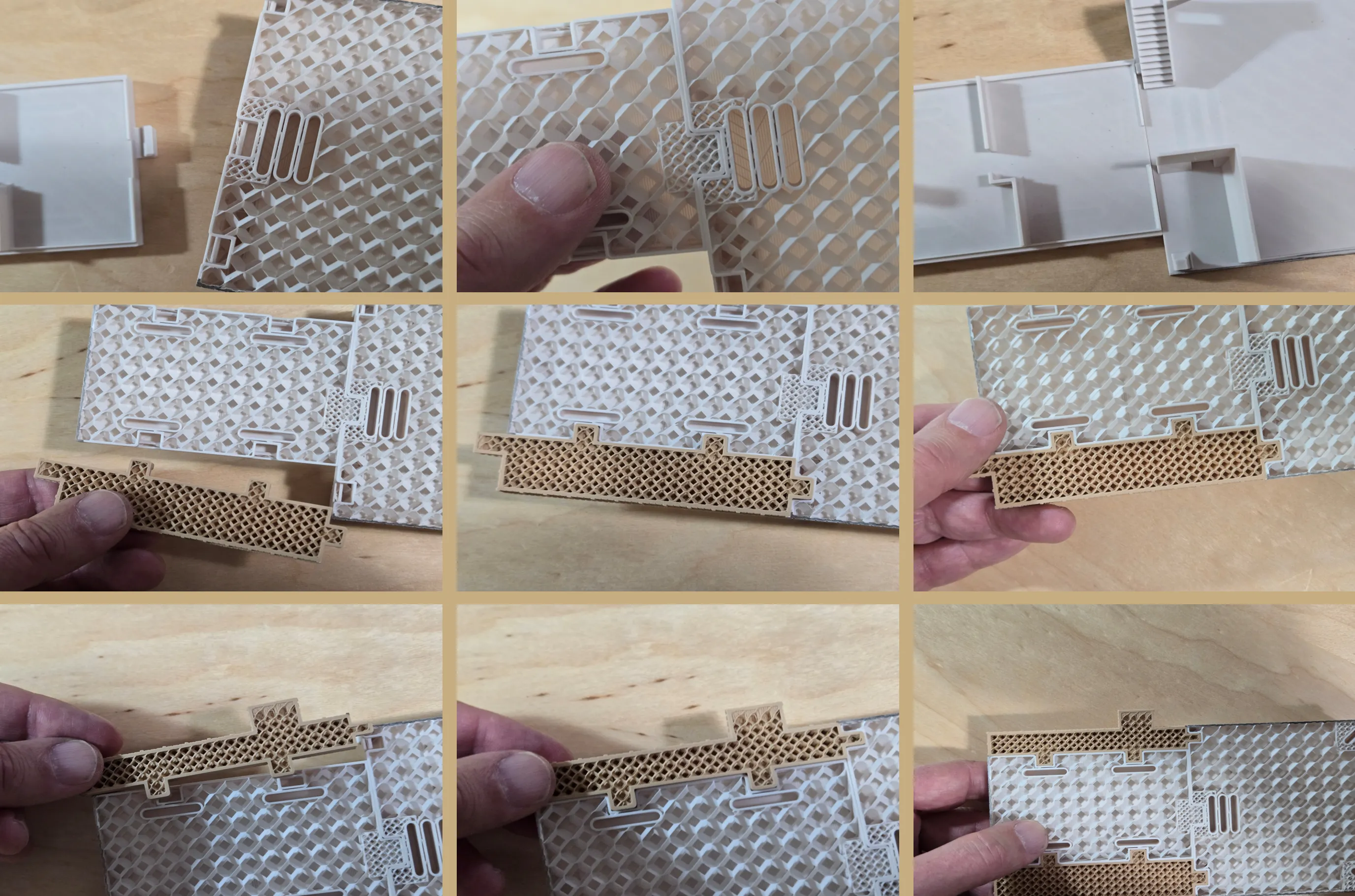
While these four parts are designed to hold together without need for gluing, you may choose to add some CA adhesive to the mating joints underneath once the parts are mated up flush together.
The right-side walls
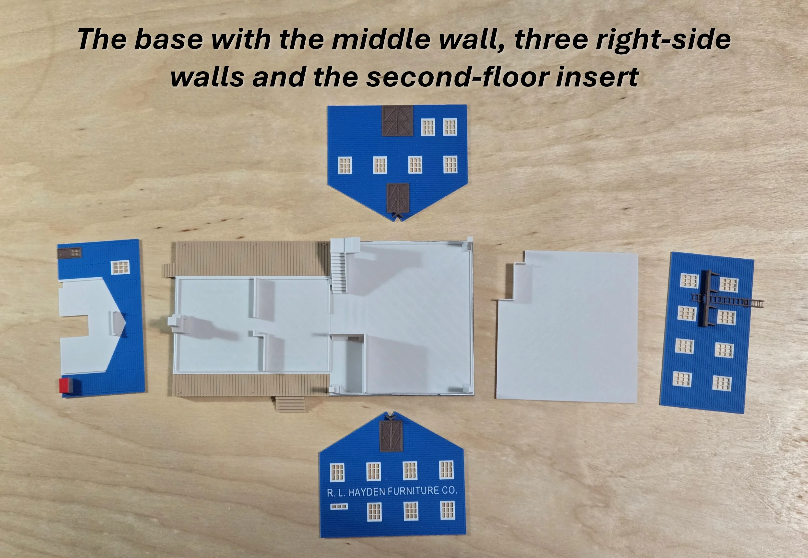
Start with the middle wall … note the alignment notch position where the middle should lock into place. Make sure that the wall sits flush with the side of the stairway and other vertical features of the base.
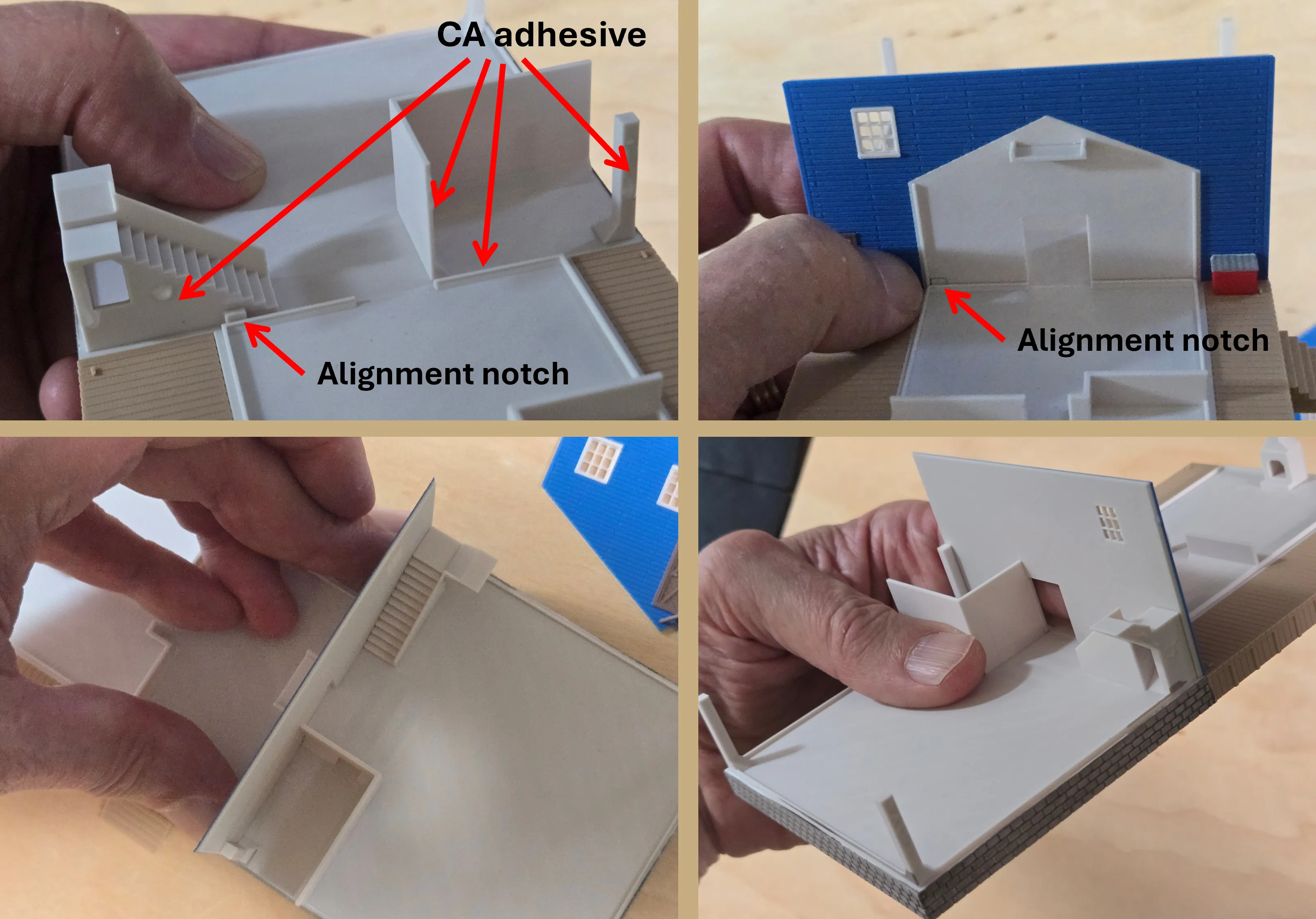
Next is the back wall … apply adhesive drop to the exposed surfaces of the vertical features as well as a small drop along the inside edge of the middle wall and a mid-point along the bottom edge … if all goes according to plan, once in place, the edge between the middle and back walls should line up very nicely.
Continue with the front wall … apply adhesive drop to the exposed surfaces of the vertical features as well as a small drop along the inside edge of the middle wall and a mid-point along the bottom edge.
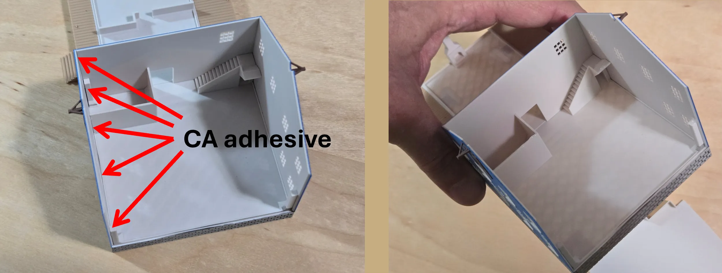
Next is installing the second floor insert … note the orientation of the second floor insert and how it aligns at the top of the stairway. Apply adhesive drops at the tops of the vertical features of the base and then place the second floor insert within the structure and flush down on those features. After the floor is in place, you may choose to add some more adhesive to help secure the front and back walls to the second floor.
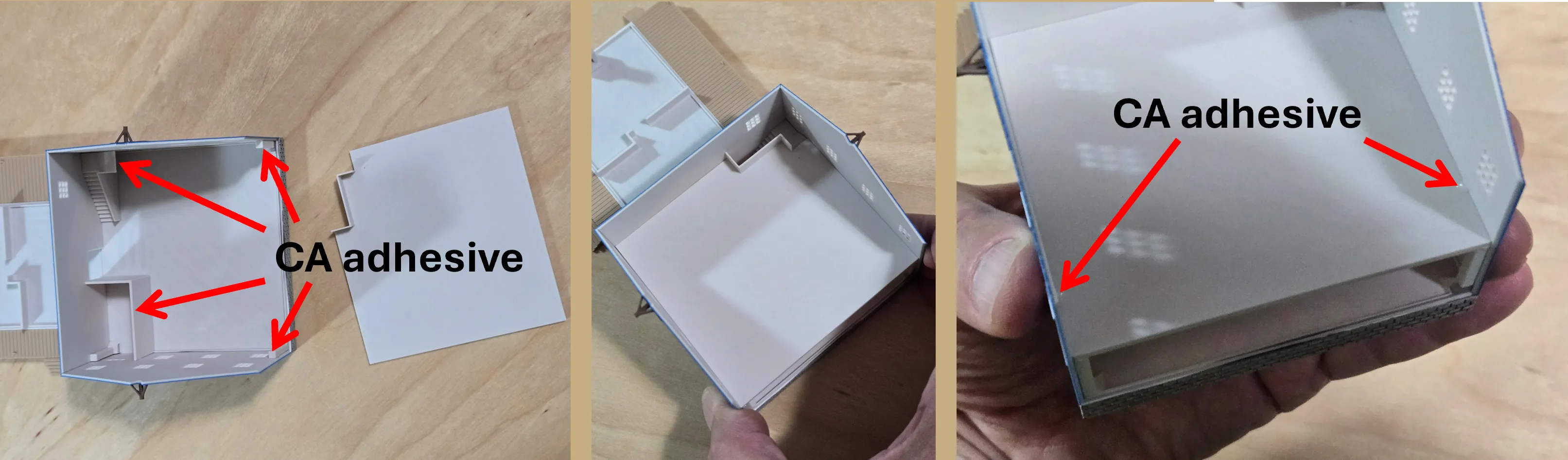
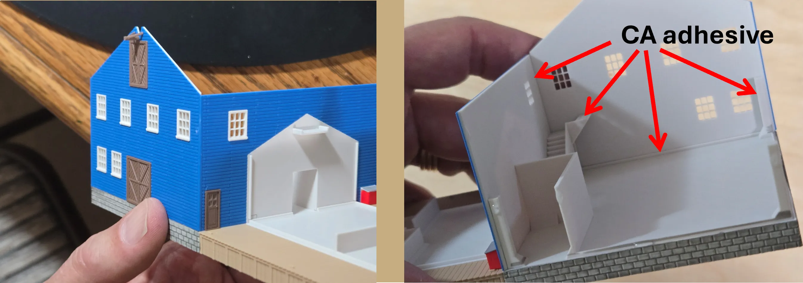
Finally, adding the right-side wall sub-assembly with the fire escape … take care not to damage the ladder when handling this wall section. Again, apply small adhesive drops to the exposed surfaces where the wall will sit.
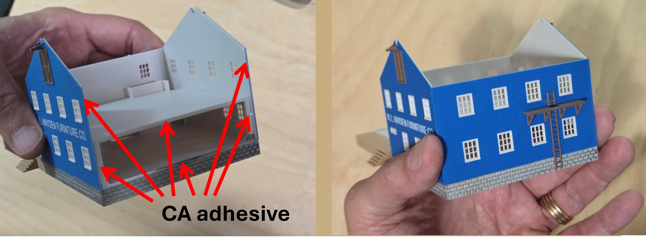
The left-side walls
Starting with the back wall, apply small adhesive drops where shown and assure that the wall is flush with the base alignment edge and vertical features once in place.
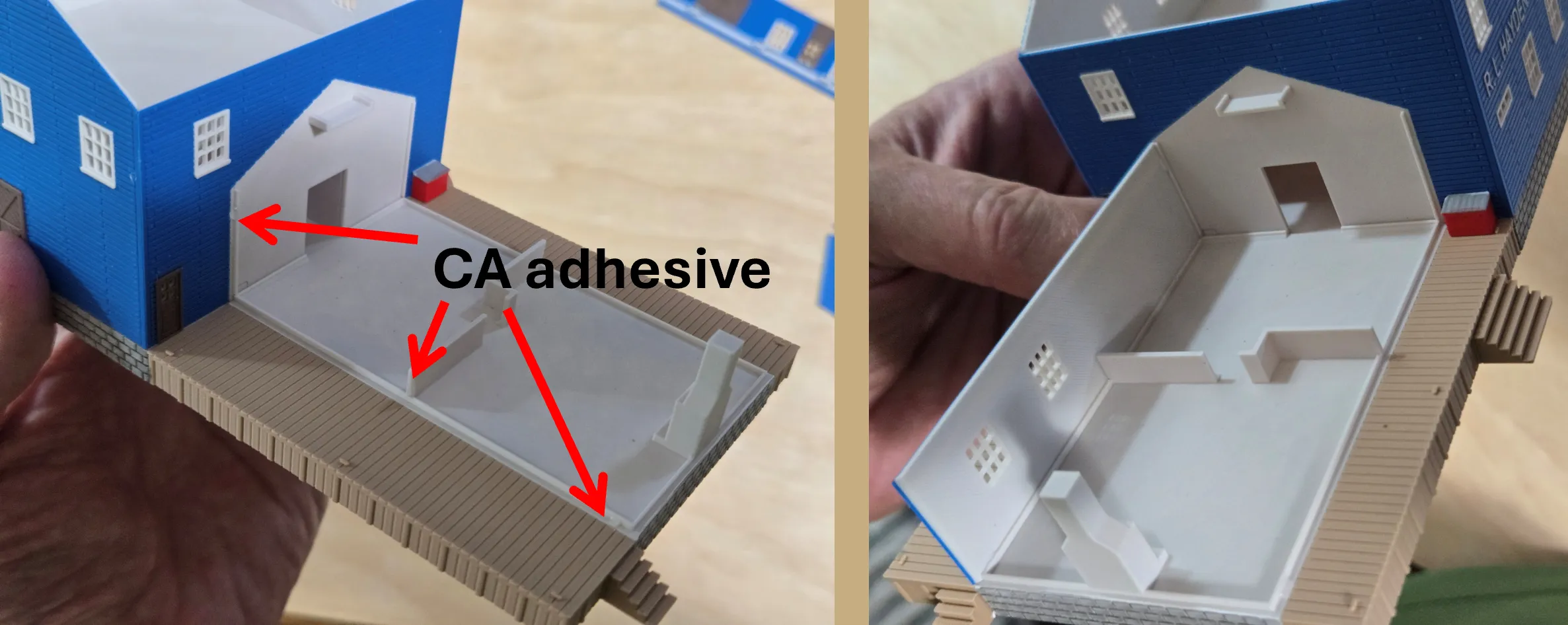
Next, add the front wall ...
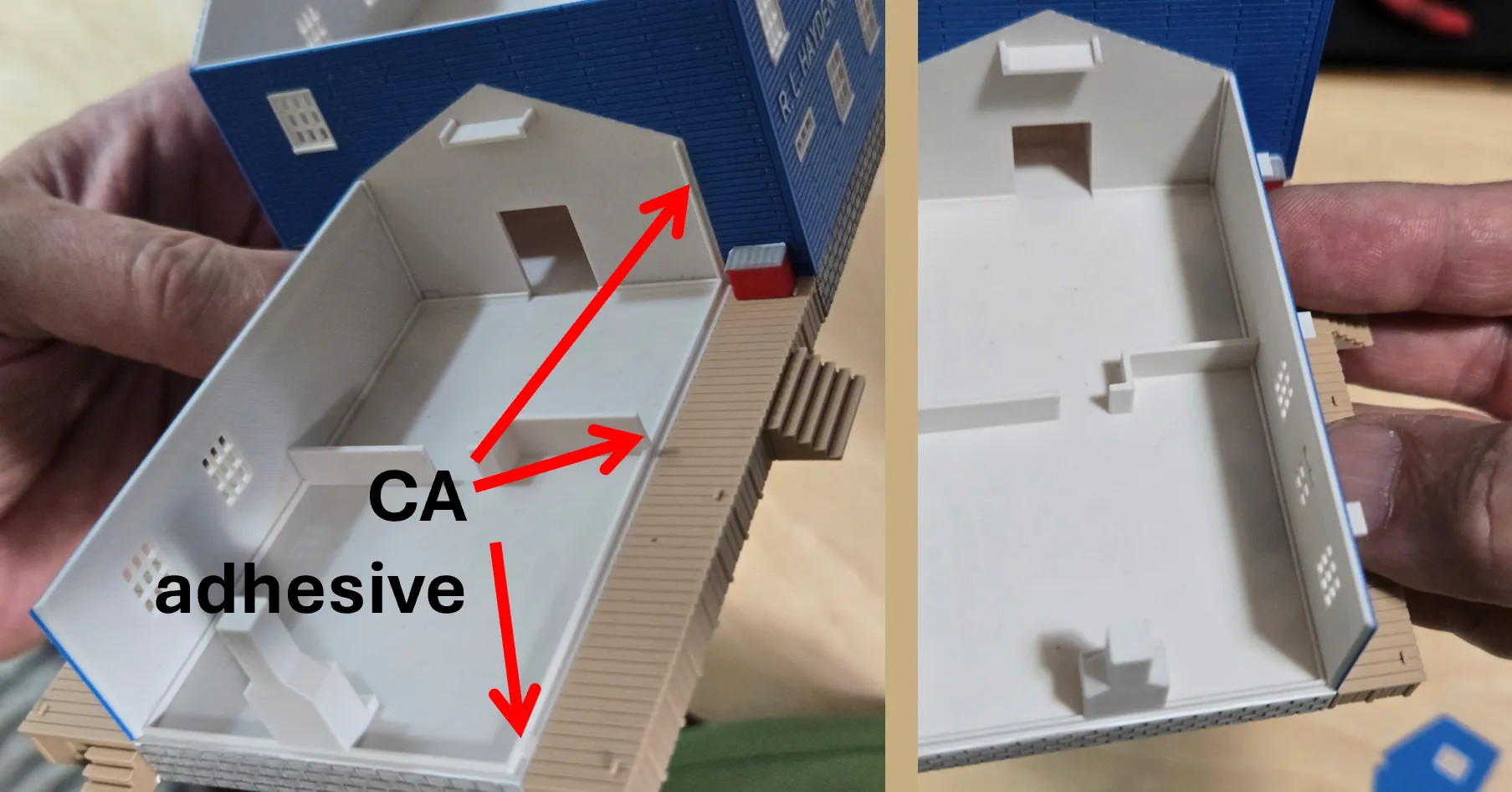
Finally, add the left-side wall using the vertical surface of the fireplace feature for adhesive and as a supporting surface for the wall.
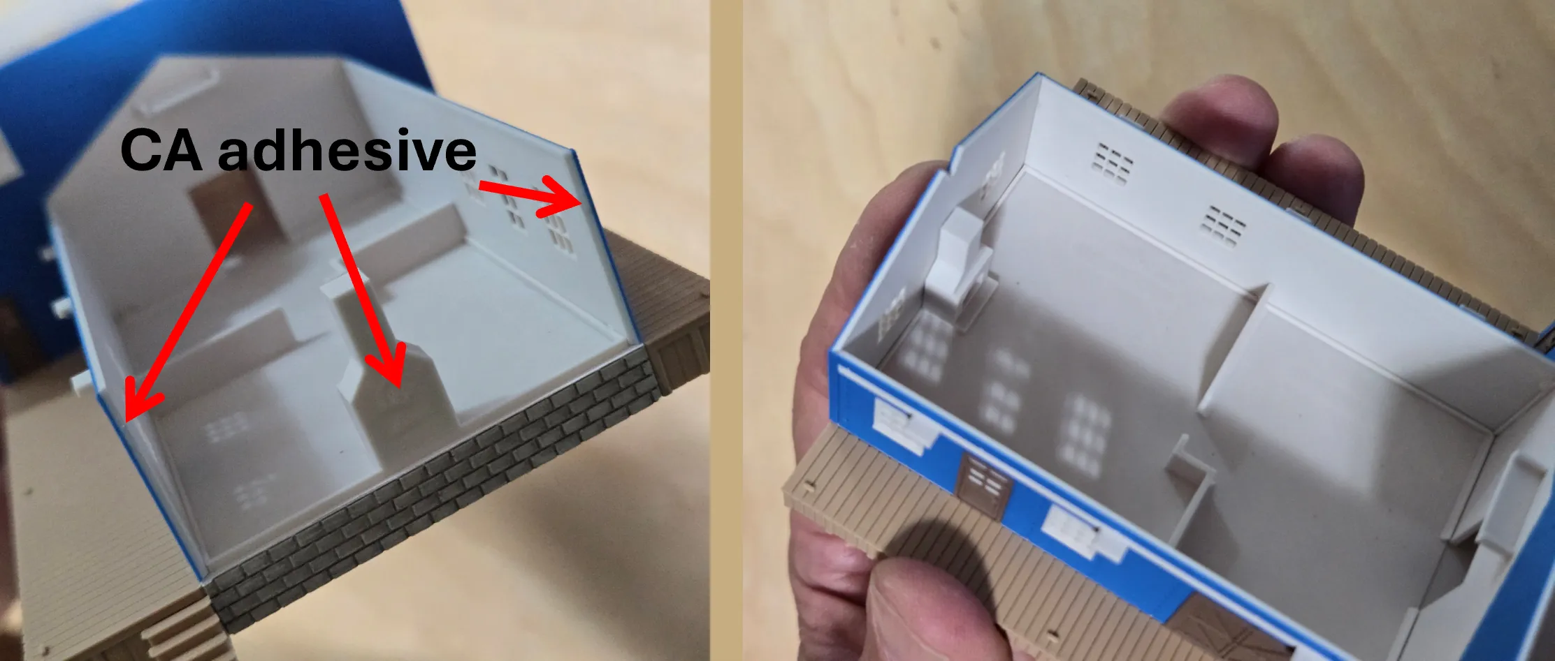
The awnings
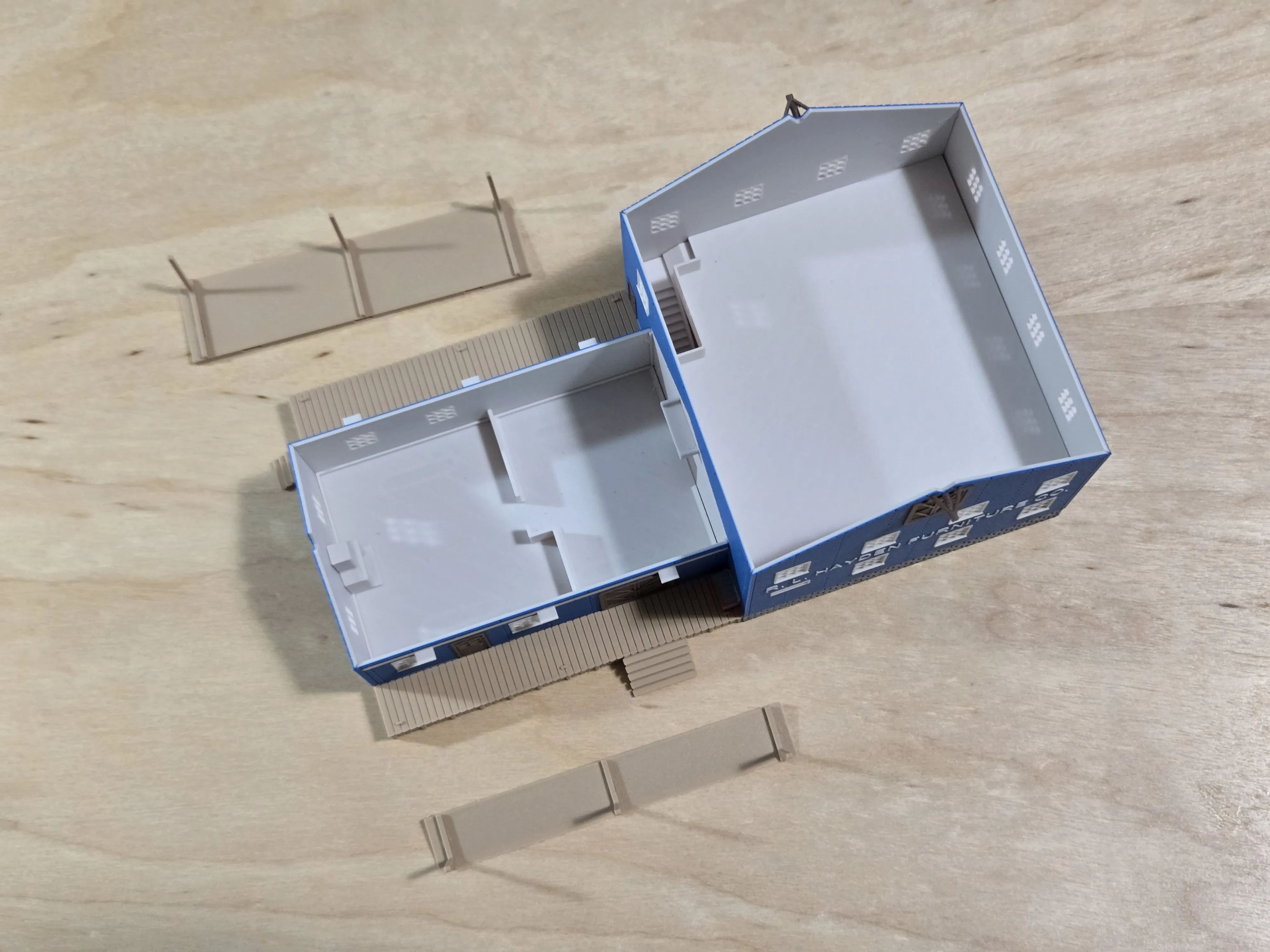
Each awning sub-assembly has three slots that are designed to align with the three support tabs on the left-side front and back walls.
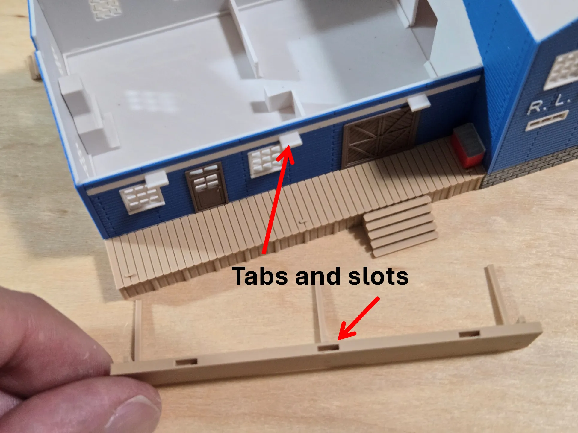
To install each awning sub-assembly, gently press the slots over the corresponding tabs … make sure to not damage the awning support legs while doing this. I generally start with one of the end slots followed by the opposite end slot, making sure that the middle slot is in its proper place as I press them together. Place a finger inside the wall as support while pressing the awning base flush to the outside of the wall. No adhesive is needed at this point.
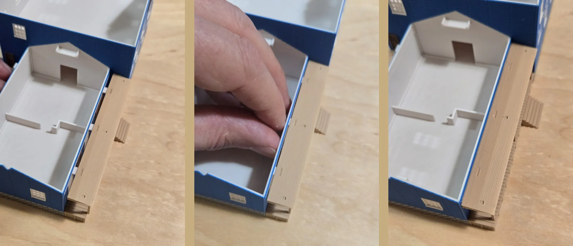
Repeat with the awning against the back wall. Make sure that the awning bases are flush with the walls before proceeding … it may take some persuasion but do be careful to not damage anything while working them on.
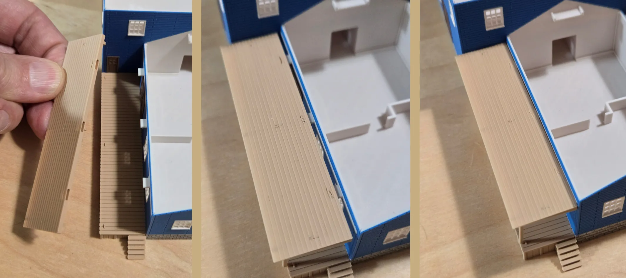
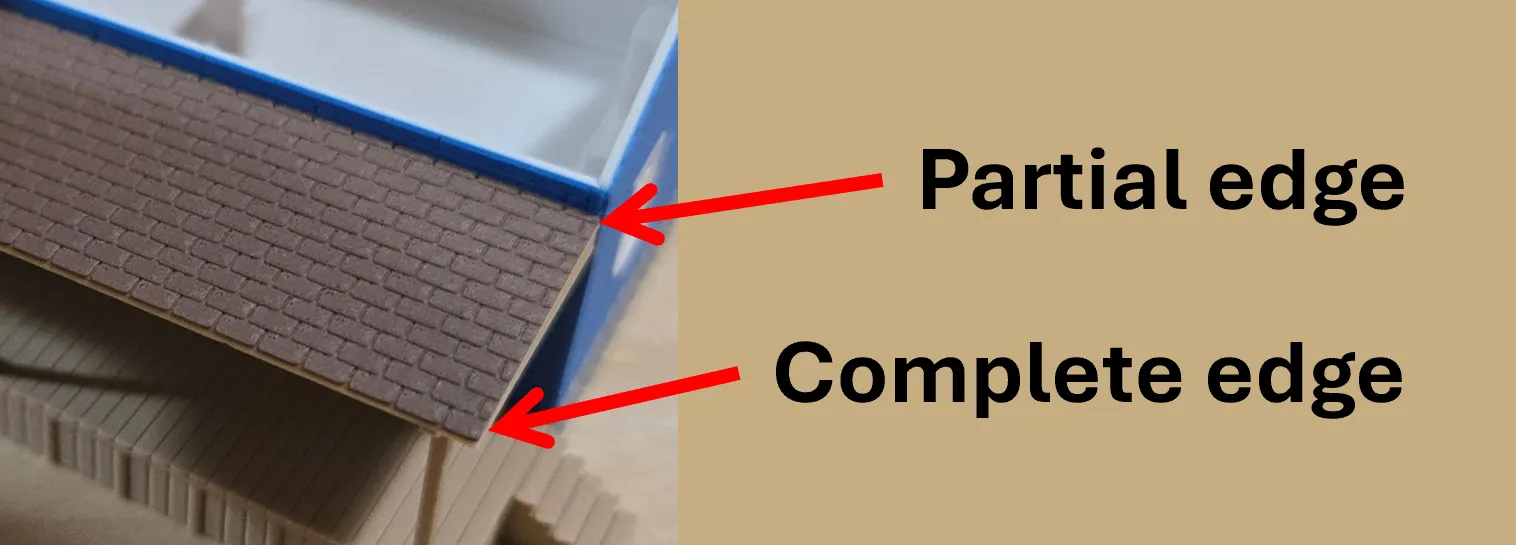
Now is time to install the awning top surfaces. Examine the awning surface parts closely … note that one of the long edges of each will have a complete shingle row and the other a partial one, the partial row should end up mounted close to the wall so that the complete row of shingles is exposed along the outer edge of the awning.
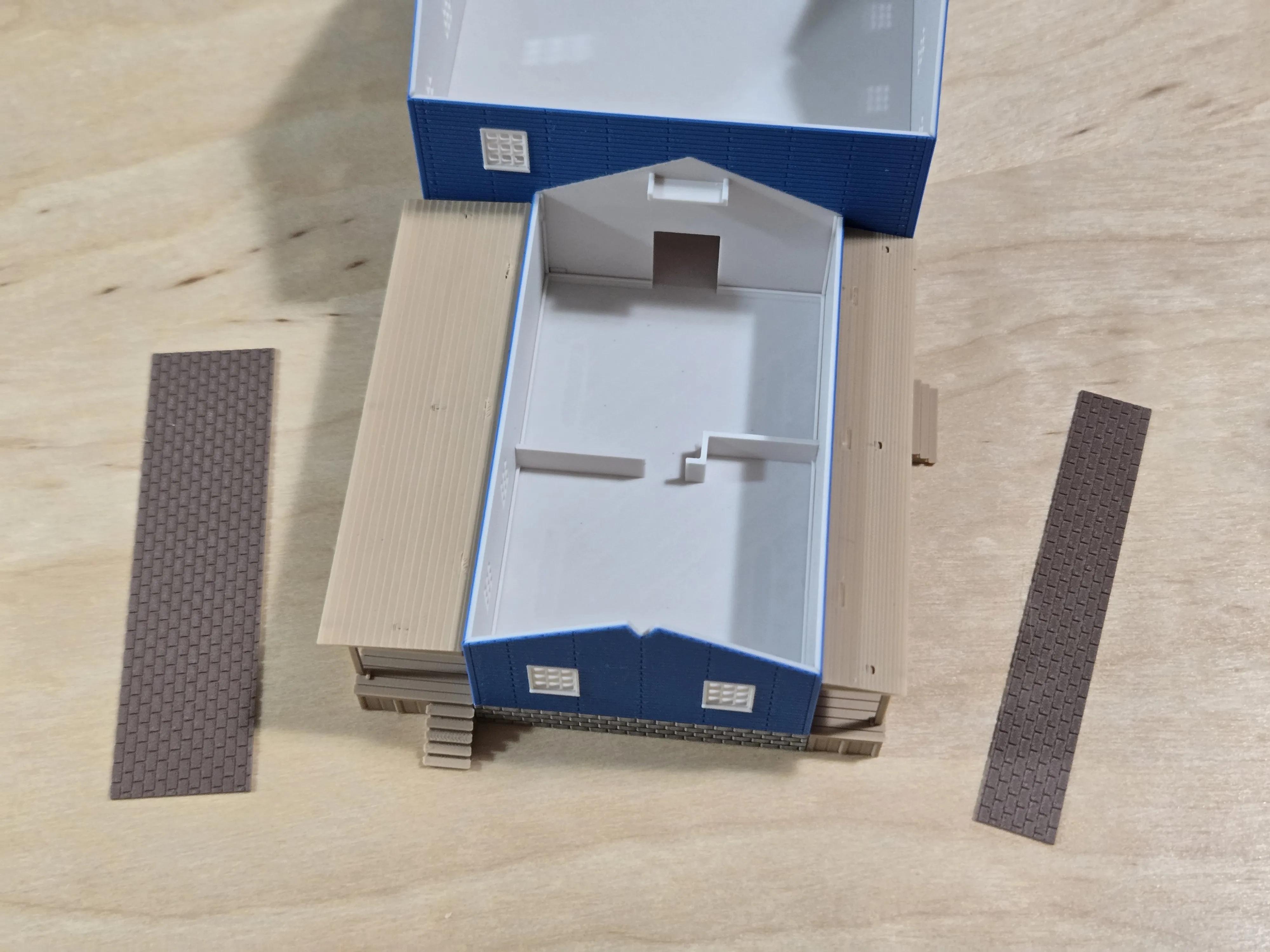
Apply adhesive drops along the edges close to the wall and the outside edge of the awning. (If, as you move the awning surface pieces into place, a bit of adhesive gets pushed up into the crack where the awning base is pressed against the wall, that would not be a bad thing :o).
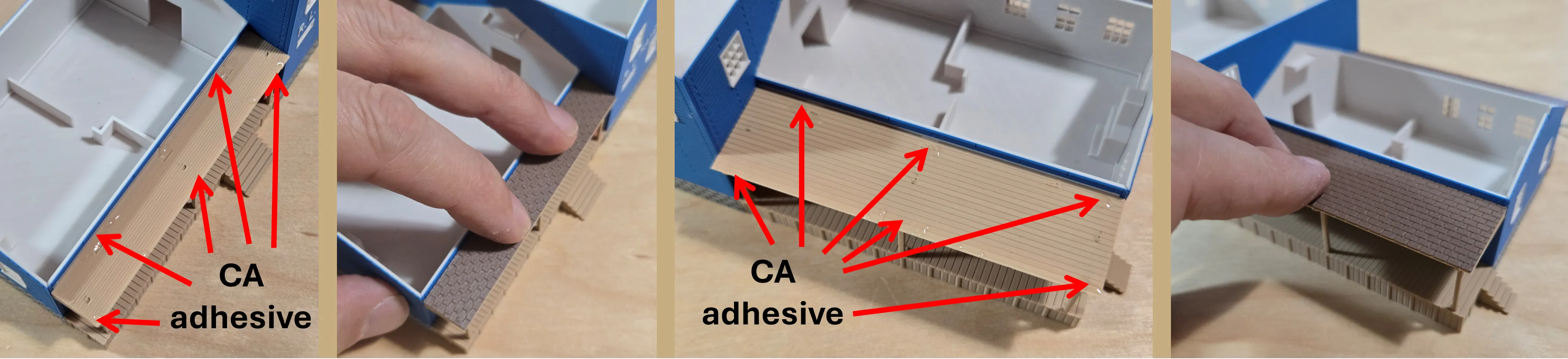
Now it is time to add some adhesive to keep the awning legs in the proper place … for this, you will need either a toothpick or another way to gab a small drop of adhesive behind each of the legs where they will sit up against the leg alignment features of the dock and deck.
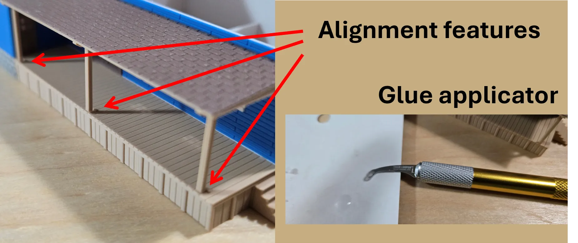
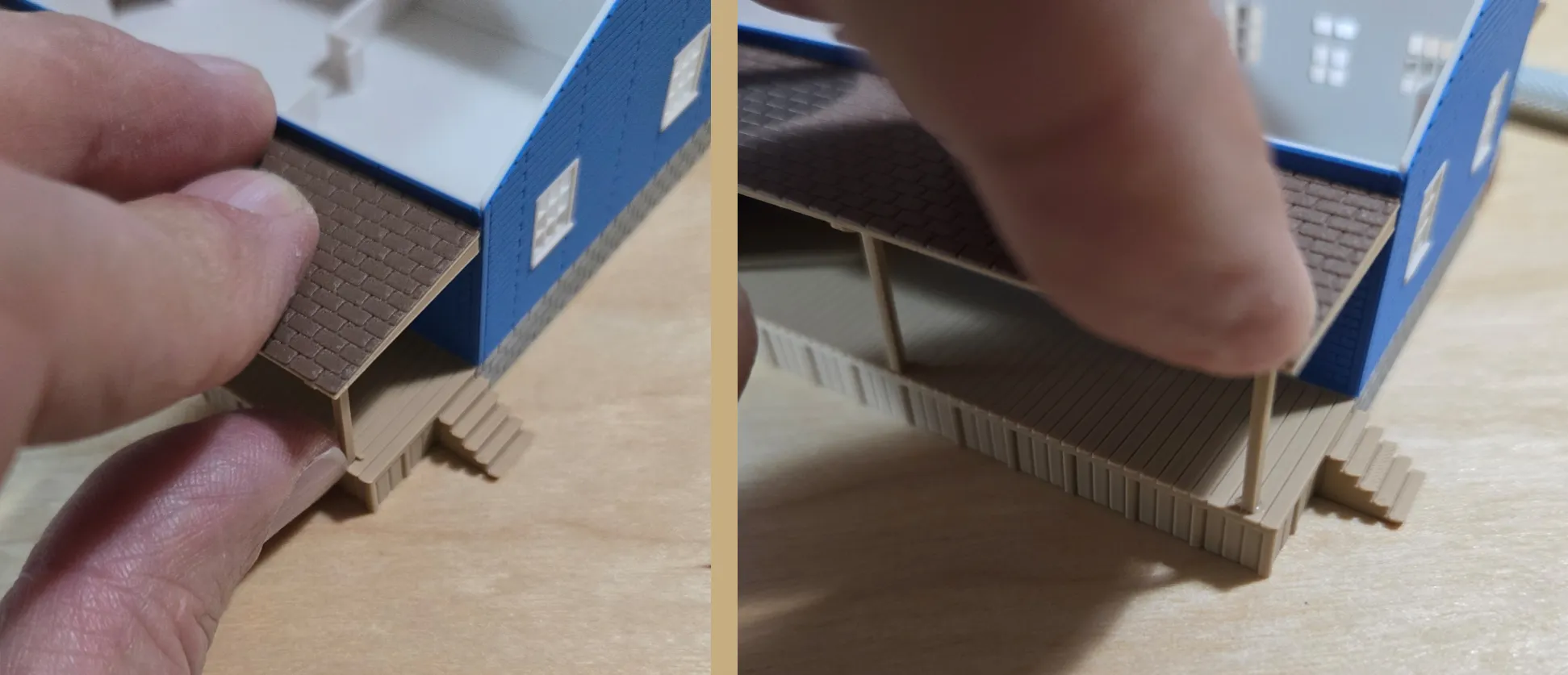
Each leg should be positioned in front of and centered on each alignment bump … the legs are a bit flexible and move easily at this point so dab on a small drop of adhesive just behind the lower back portion of the leg and then move it into place followed by gently pressing down on the awning while the adhesive takes hold. Do this for each leg, one at a time until you have secured all three back-side legs followed by all three front-side legs.
The roof support beams
The left-side roof support beam fits within the notch at the top of the left-side wall and the beam support shelf of the middle wall. Once in position, make sure that the beam is sitting flush with the surfaces of the middle wall support shelf and the inside of the left-wall.
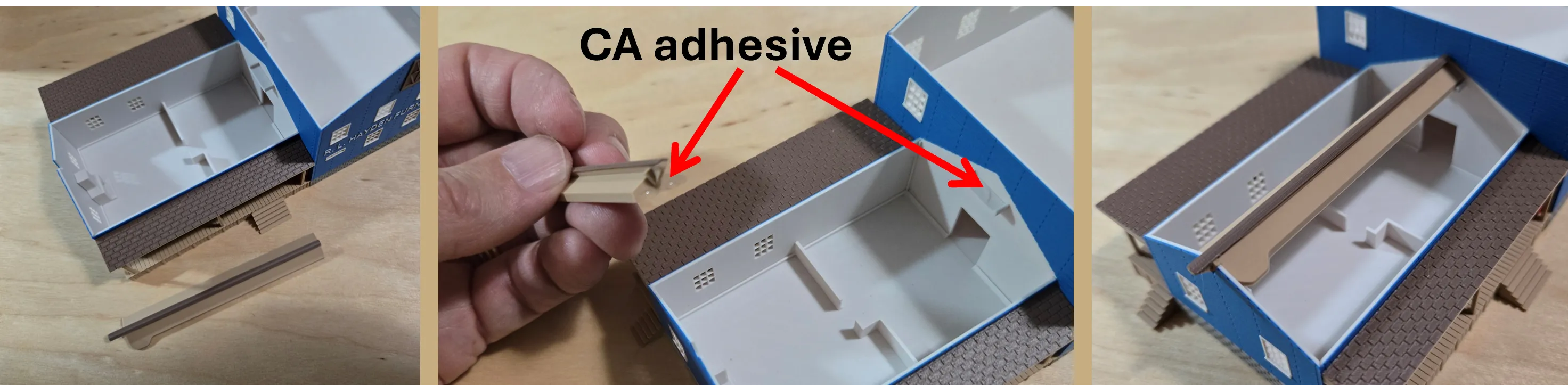
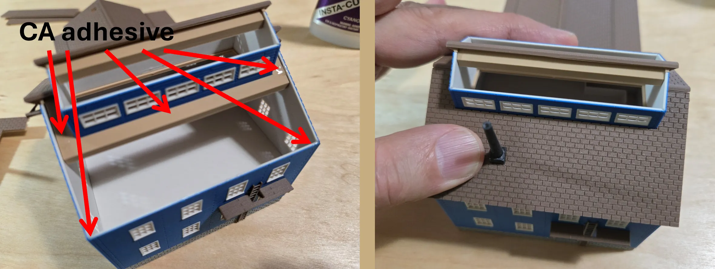
The right-side clerestory sub-assembly also serves as the roof support beam for the main right-side roof sections. Apply adhesive to both ends where indicated and position the beam structure between the notches of the right-side front and back walls. Key to this step is making sure that the clesestory sub-assembly is sitting level/balanced between the walls … you should be able to judge it being level by observing how the roof support surfaces align evenly with the top edges of the walls on both sides.
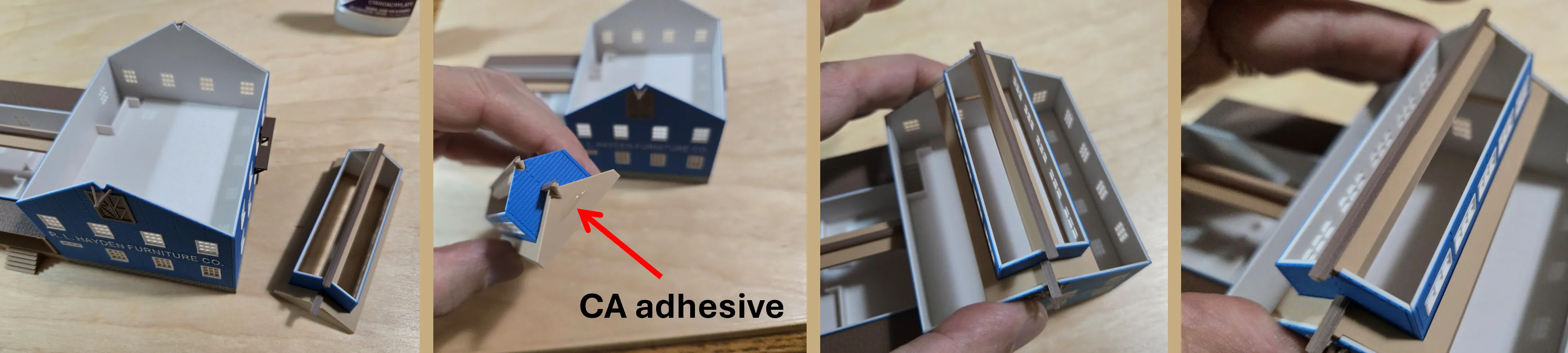
The roof sections
For the left-side roof sections, note that the underside of each roof panel there are recessed areas that are intended to be positioned over the top edges of the walls being covered … there is no need to specifically align these recesses as the alignment of the roof sections are more dependent on getting the top edges of the roof panels snugly positioned under the beam's top finished surface as seen in the final image of this illustration.
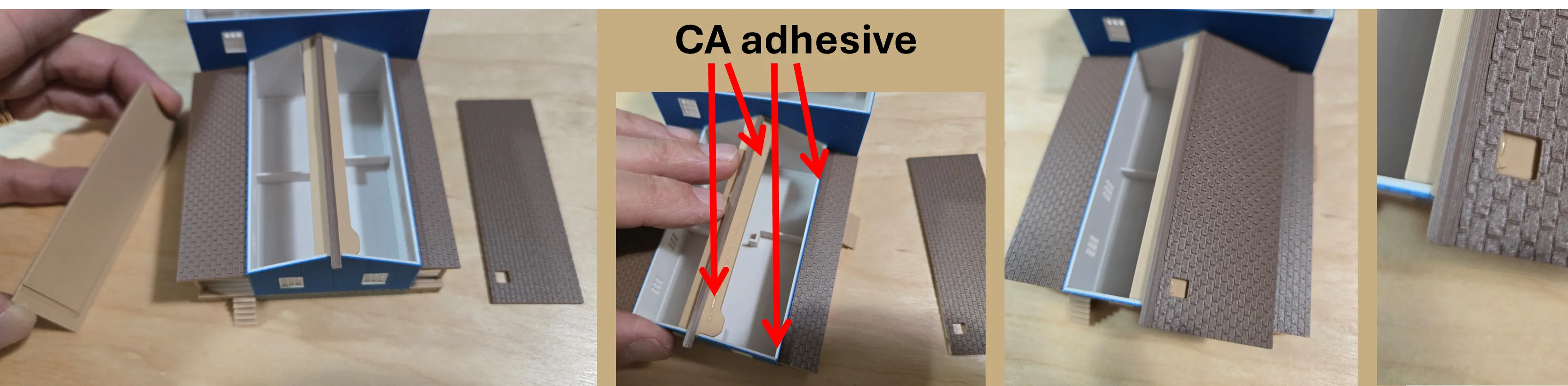
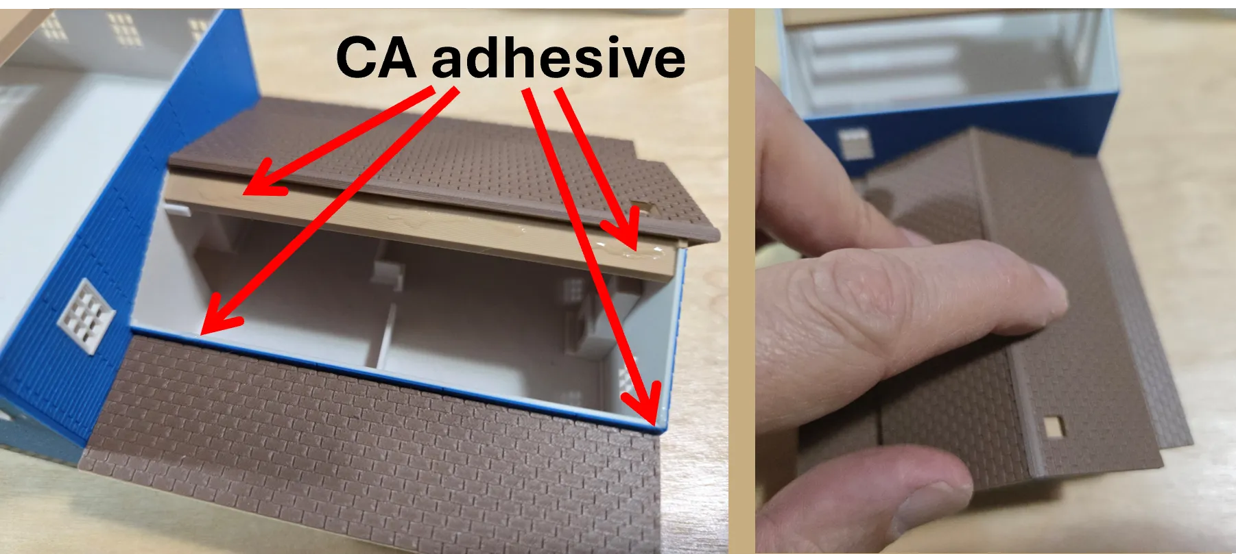
On the right side of our factory, the two main roof sections are designed to fit around the clerestory with the main roof section that has the factory chimney being mounted on the far right side. Take care to not damage the chimney when attaching that roof section.
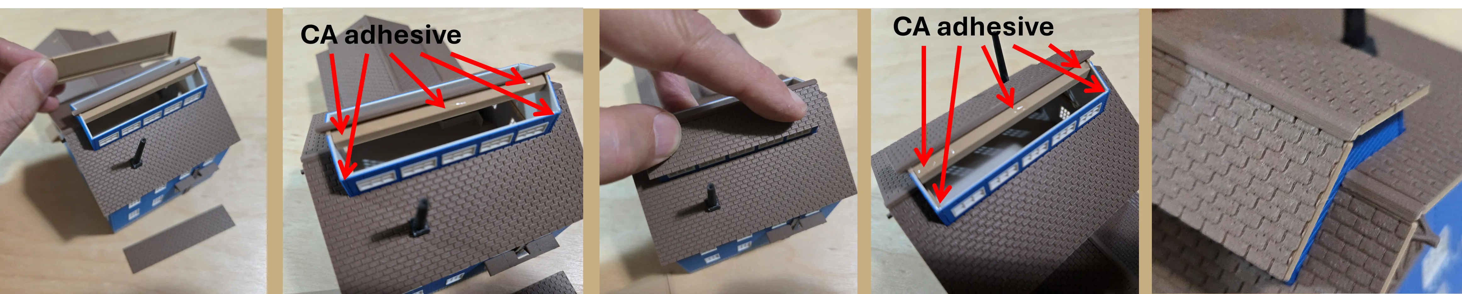
Finally, attach the remaining small roof sections to the top of the clerestory structure.
Some final details
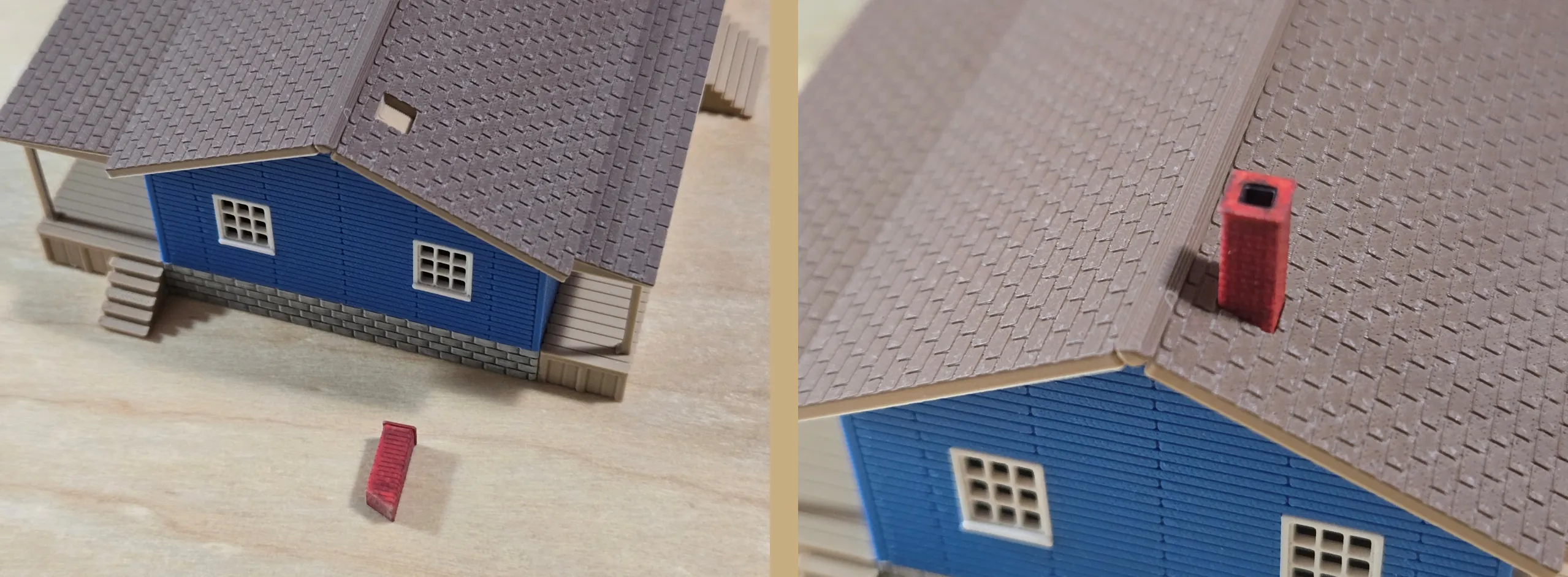
The left-side chimney needs to be installed using a little bit of adhesive … make sure that the lower angled surface of the chimney sits flush with the exposed portion of the beam such that the chimney sits vertical on the roof.
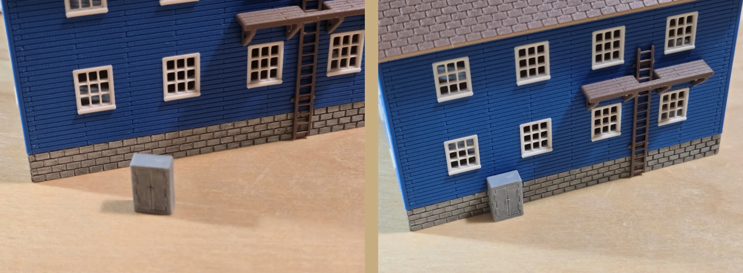
All that remains now are the shipping crates and the utility cabinet. You can see where I've chosen to position the utility cabinet on the side of the factory, using a small dot of adhesive on the upper back of the cabinet to hold it against the wall.
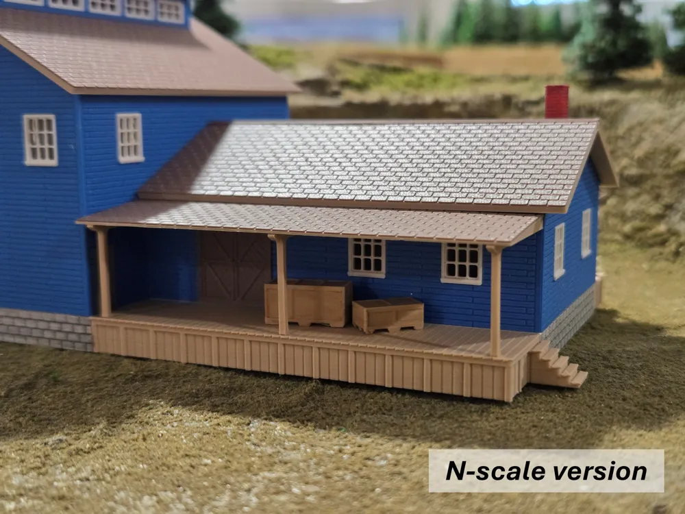
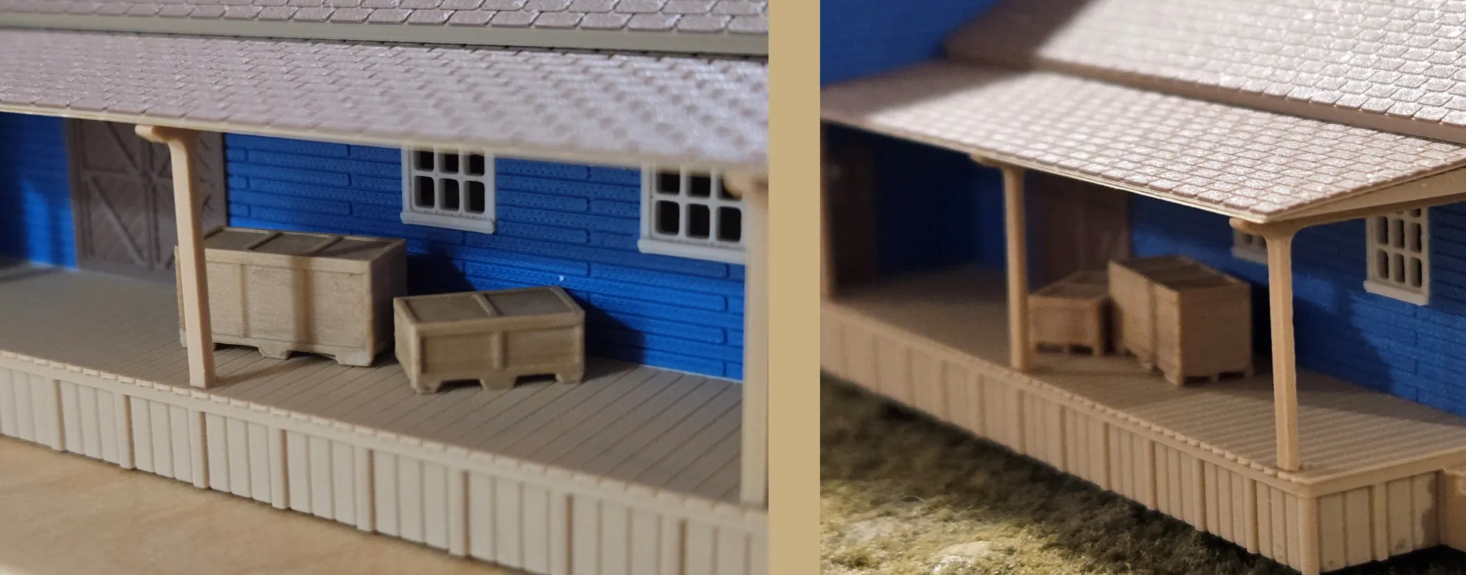
Shipping crate placement is up to you … here are a couple of examples where the crates have been left on the trackside dock.
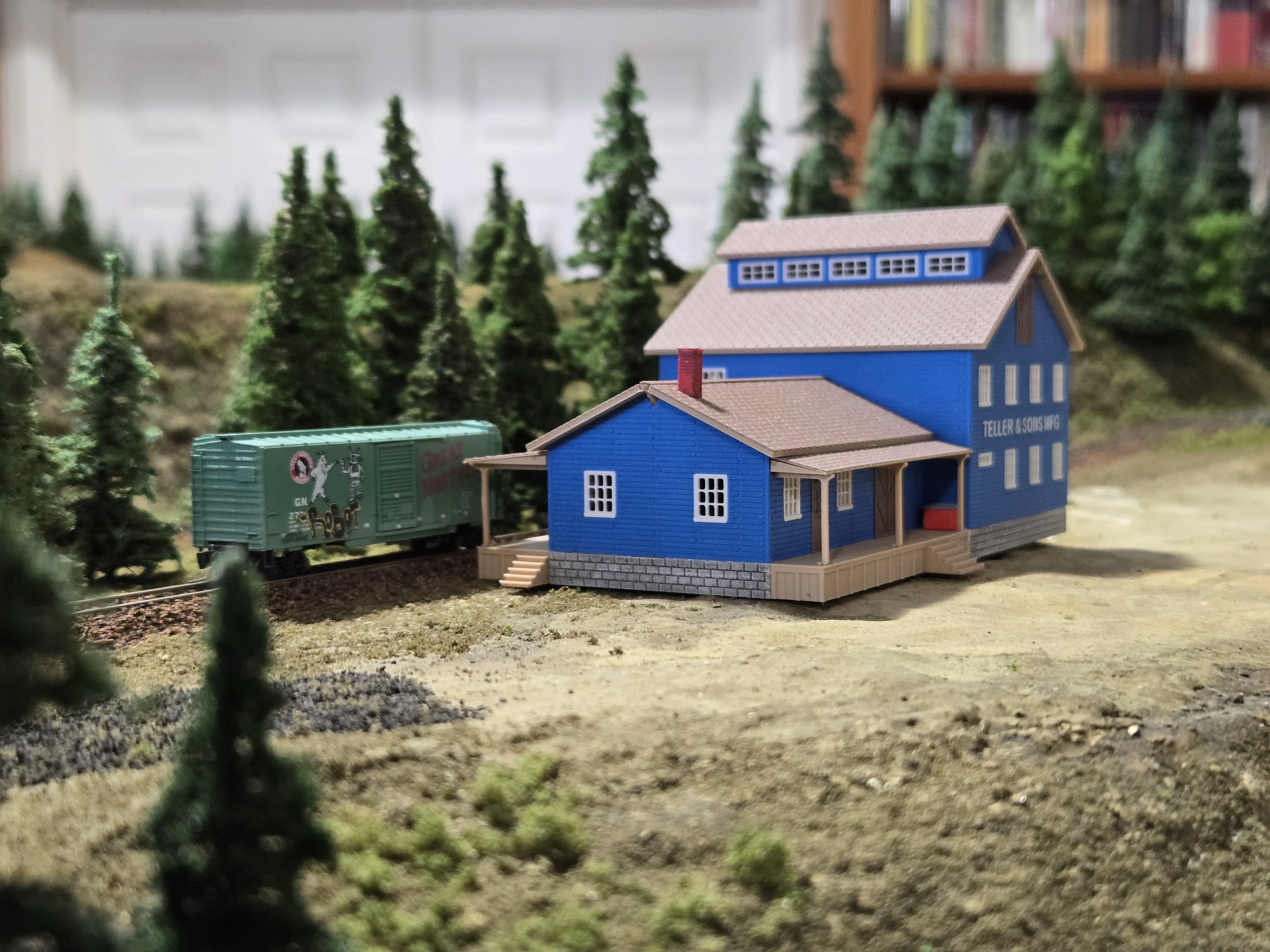
I hope that copies of this model find good homes on model train layouts around the world … I have a spot on my Z-scale layout where Teller & Sons Manufacturing will definitely be doing business … if you are careful and patient, you should be able to produce a nice looking structure … have fun with it!
Boost Me (for free)
Model developers like myself can always do with a bit of encouragement. Posting a rating with pictures, tagging our models with a Like, or even giving us a Boost is always appreciated. Thanks!
License

You shall not share, sub-license, sell, rent, host, transfer, or distribute in any way the digital or 3D printed versions of this object, nor any other derivative work of this object in its digital or physical format (including - but not limited to - remixes of this object, and hosting on other digital platforms). The objects may not be used without permission in any way whatsoever in which you charge money, or collect fees.


Comment & Rating (1)