
Polaroid 110A 110B 4x5 Graflok Conversion

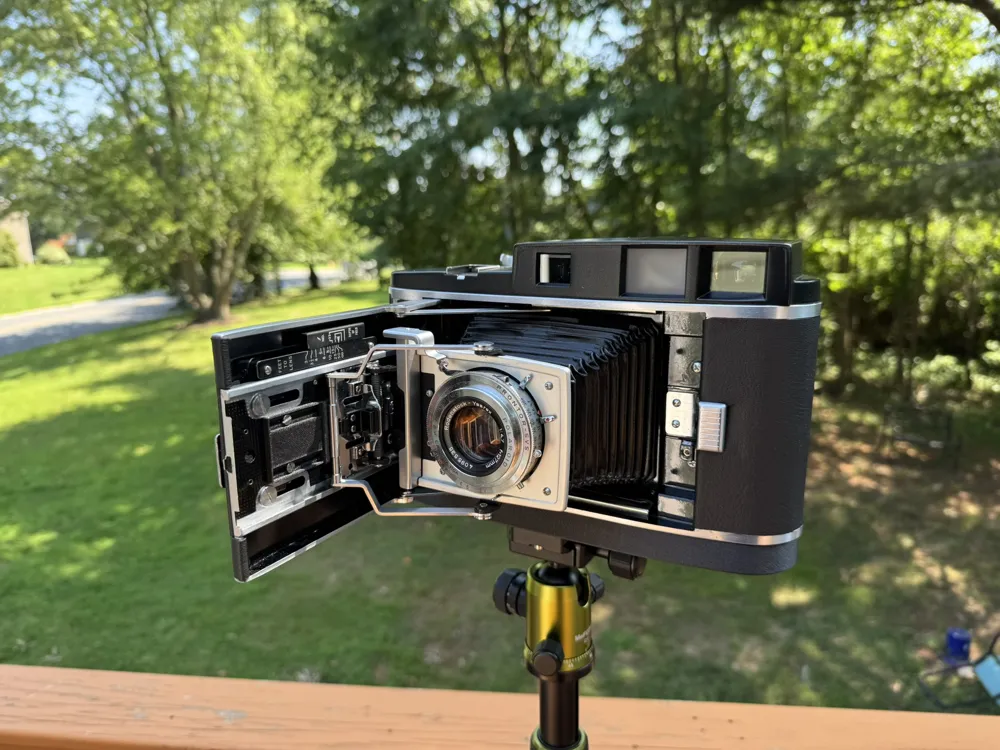
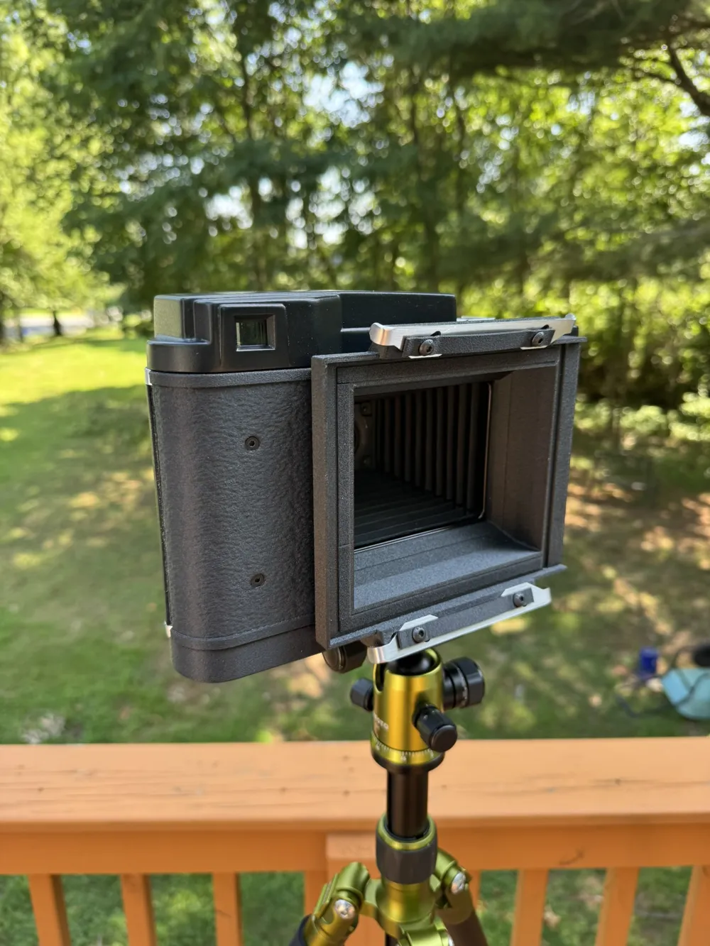
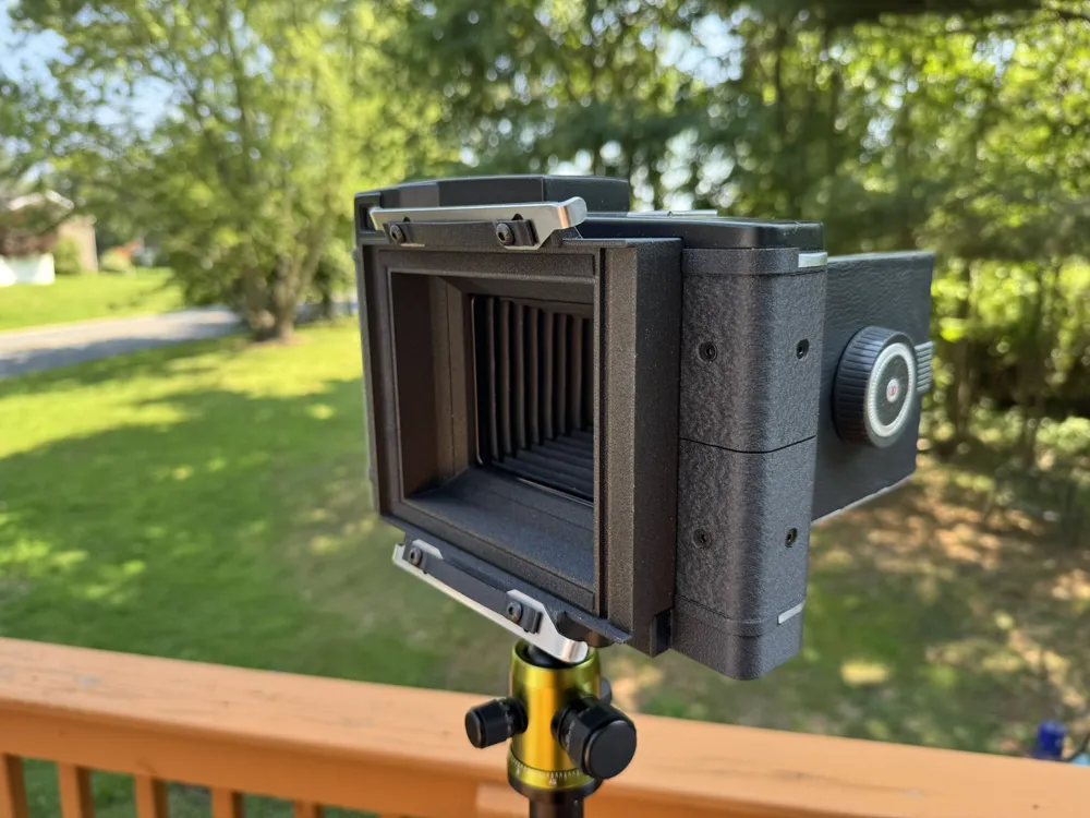
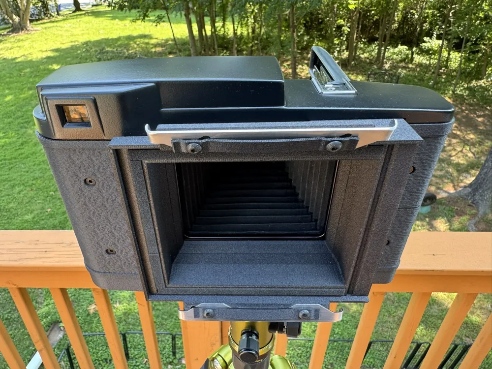
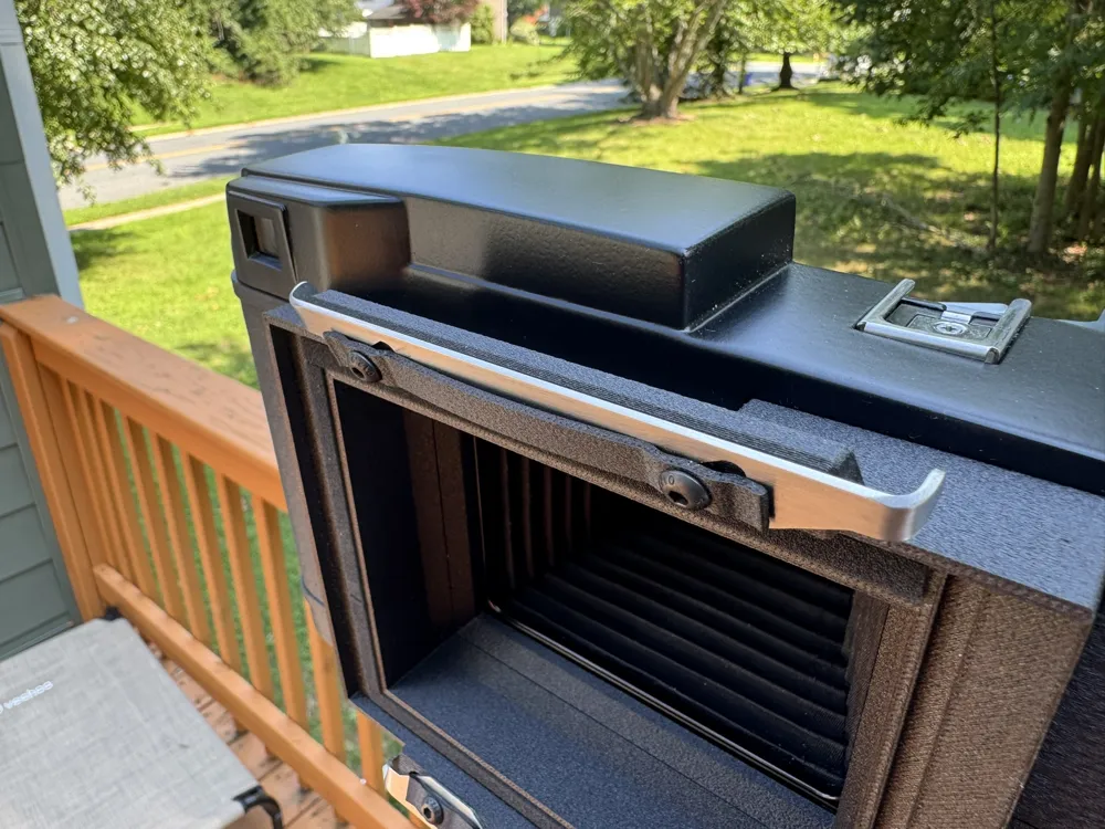
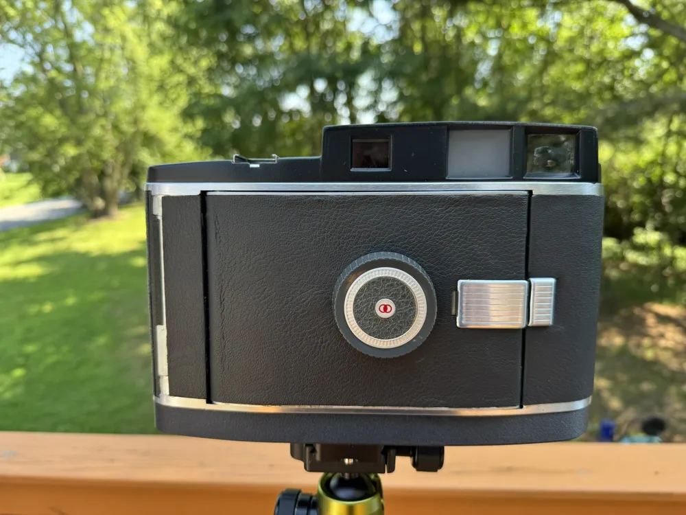
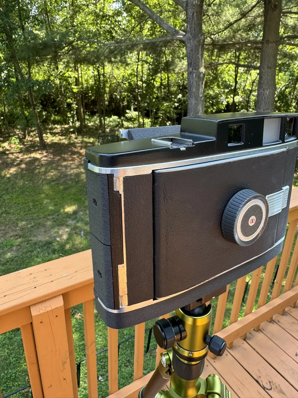
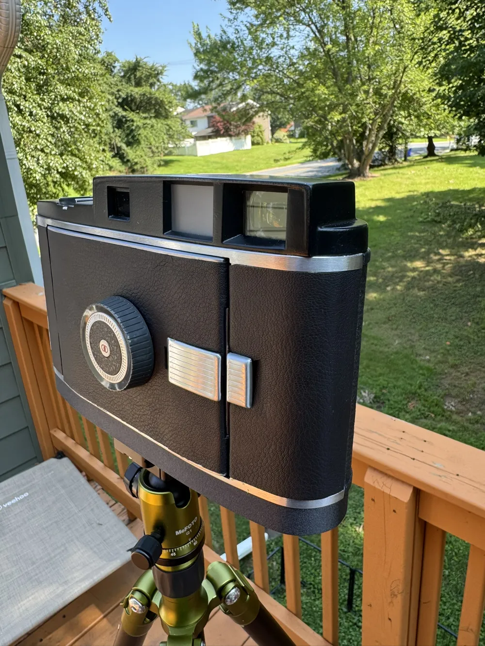
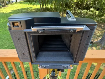
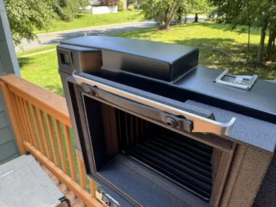
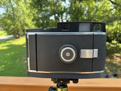
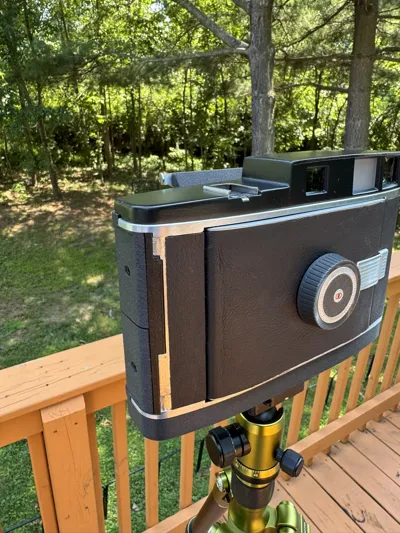
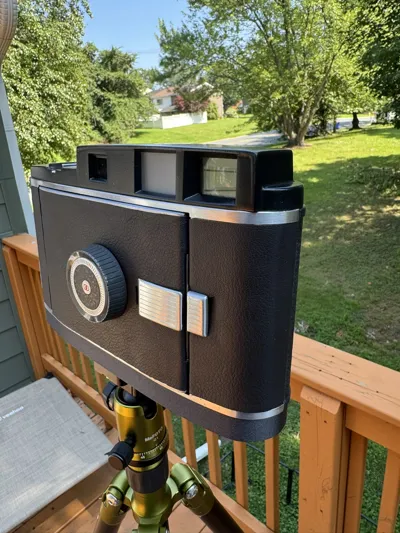
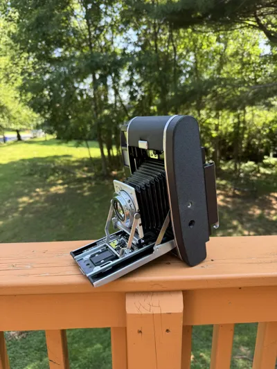
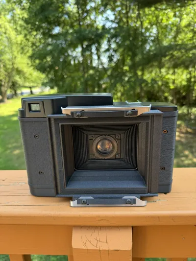
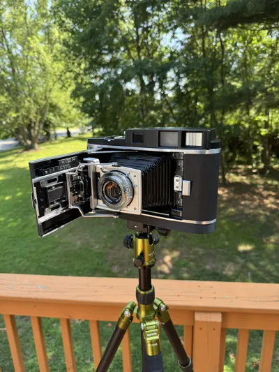
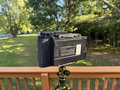
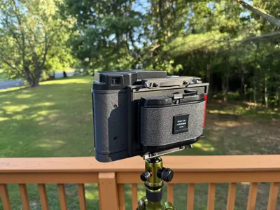
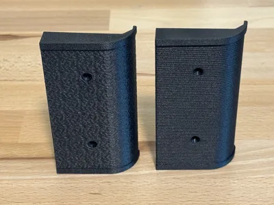
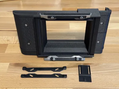
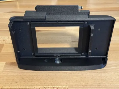
Print Profile(1)
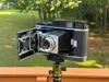
Bill of Materials


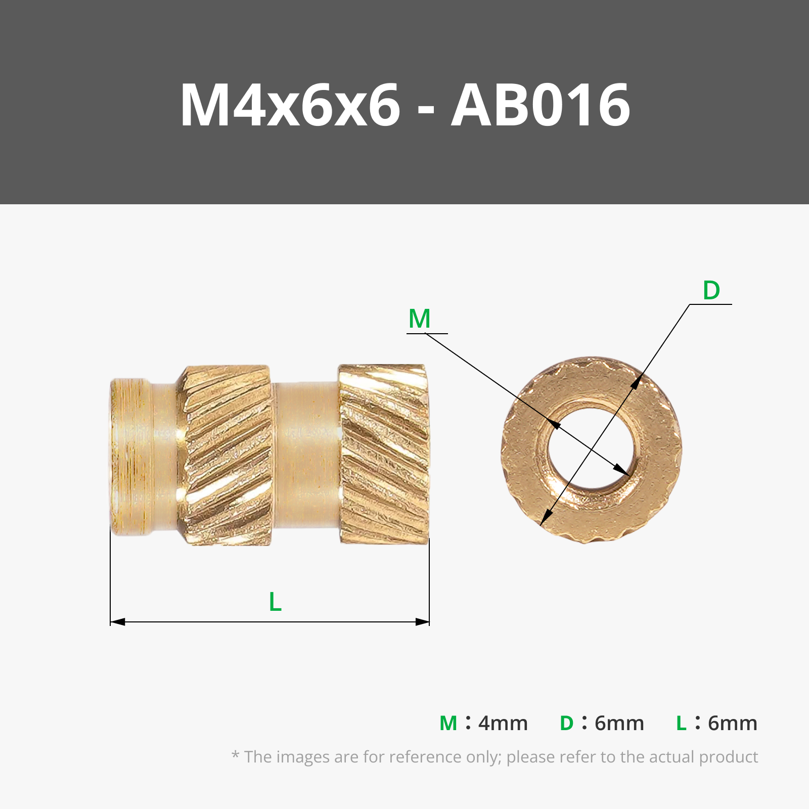


- Picture Frame Turn Botton Set x 1: w/ #2 screws
- 5" x 7" 3mm Acrylic Sheet - Modified x 1: Cut down to 4" x 5", matte/frosted on one side
- 2mm Light Seal Foam x 1:
- 1/4-20 x 5/16 Tee Nut x 1: Home Depot Everbilt 825001
- 1/4-20 x 1/2 SHCS x 1:
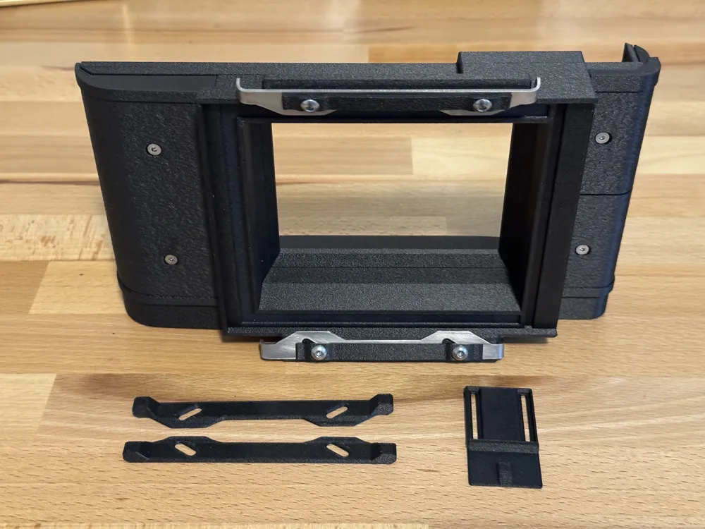
- Graflok Slide Lock x 2: Laser Cut Part
Description
Overview
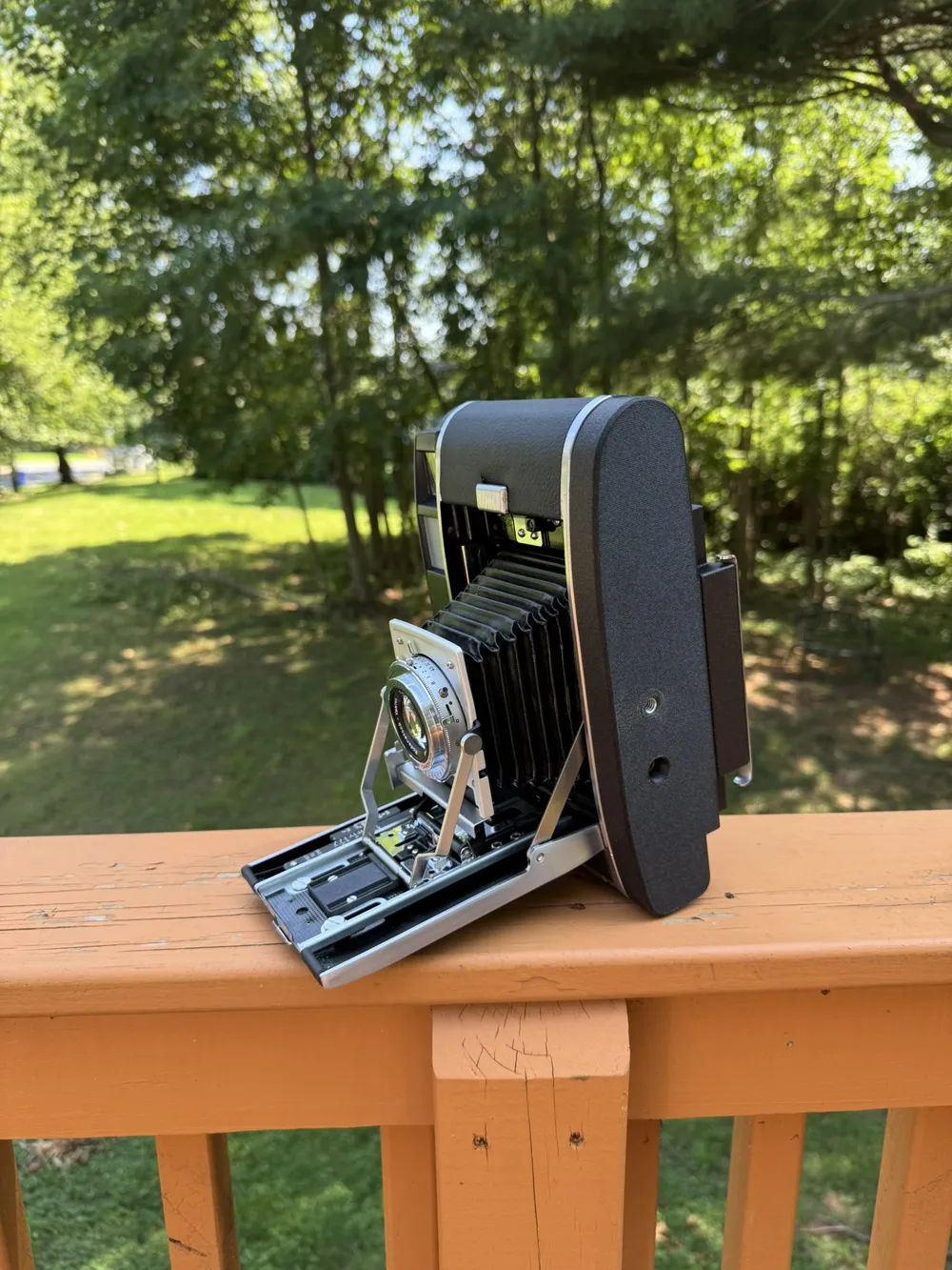
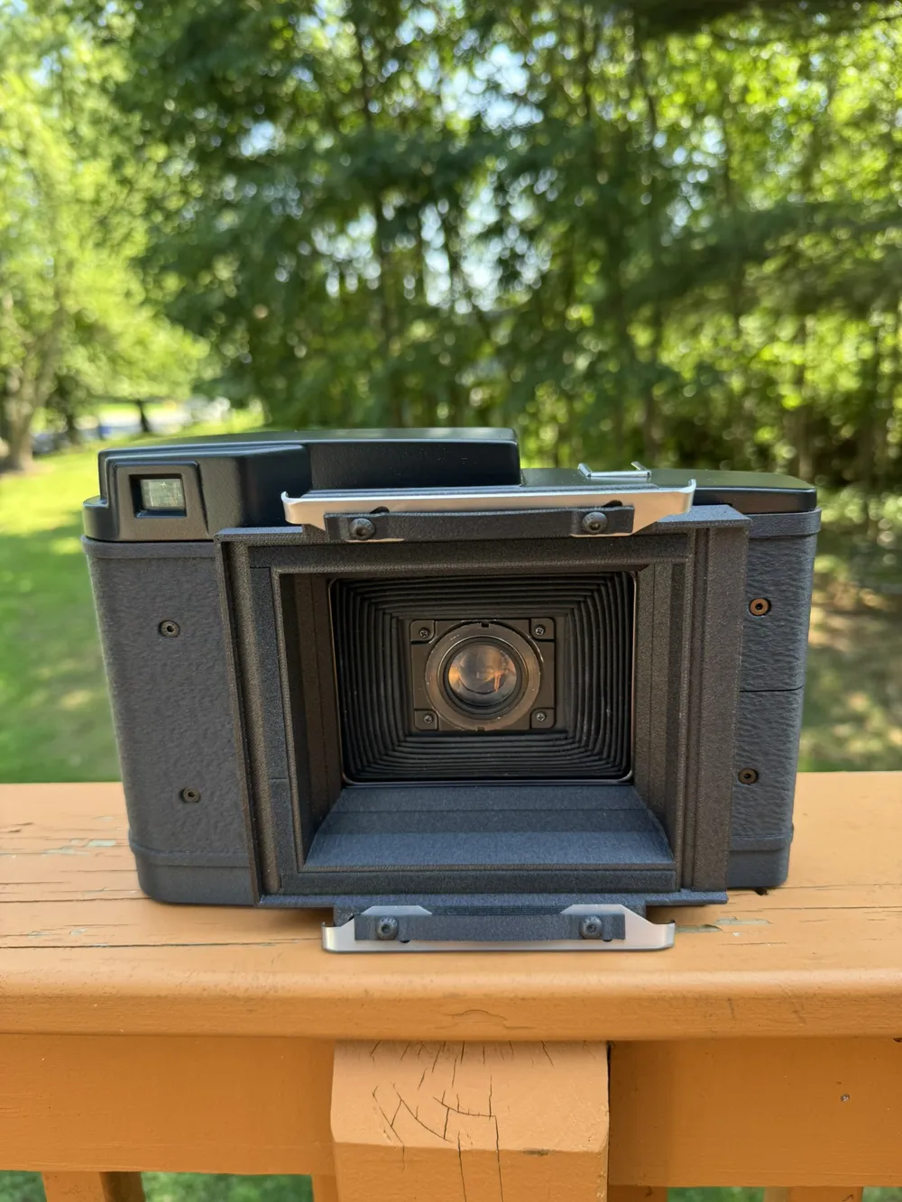
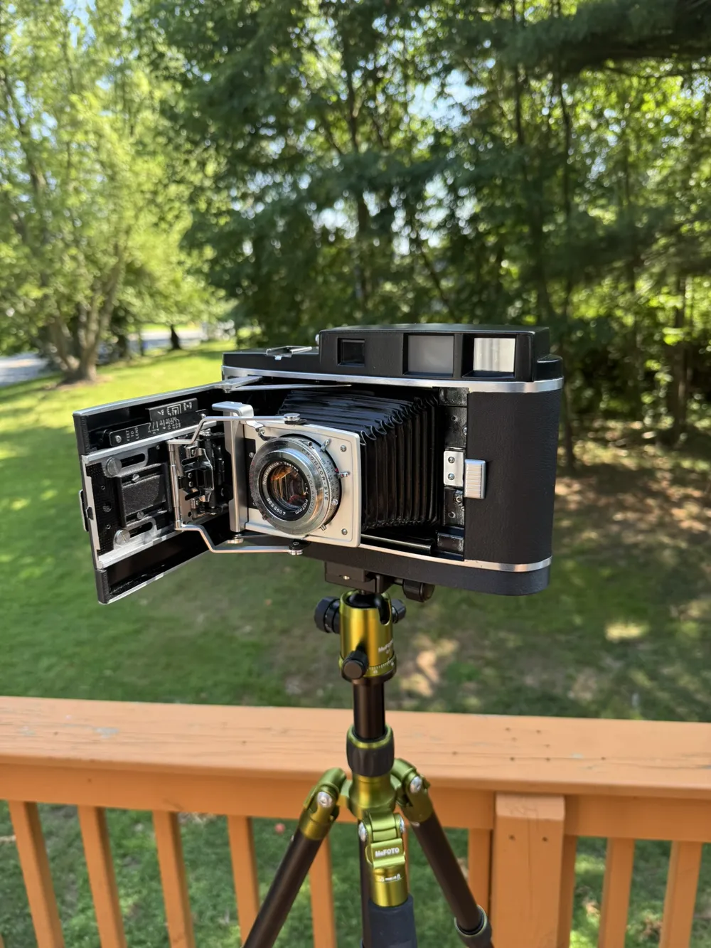
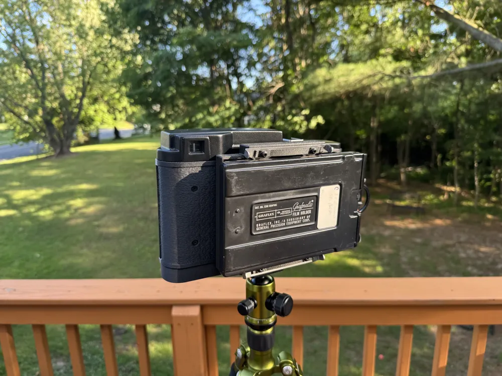
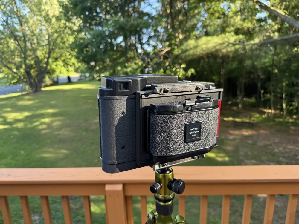
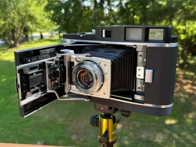
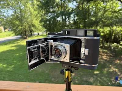
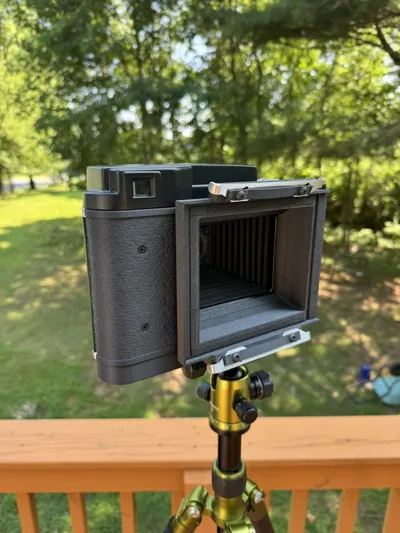
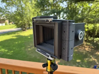
This is a 4x5 Graflok conversion for Polaroid 110A and 110B cameras. You can use this with any standard 4x5 graflok backs - grafmatics, 4x5 120 roll film backs, lomograflok, etc. This has centered framing and full 4x5 coverage. This is an extensive project so please read the full description before proceeding.
My goal was to make a high quality, well documented 4X5 conversion for the 110 cameras that worked well, looked good, and was easy to print/assemble. This is far from the first conversion and the previously published versions were invaluable for creating my own take on it. Please check out the list at the bottom for my references and other conversion sources.
This is published for non-commercial use.
Kits Available
Due to multiple requests I've set up an etsy listing for kits. These are made-to-order with options ranging from hardware only to fully printed/assembled packages.
https://www.etsy.com/listing/4537916944/polaroid-110b-pathfinder-4x5-conversion
Camera Selection and Destructive Modification
This conversion is ideally suited for the 110B version. It can work on the 110A but the viewfinder will still be obscured. I am working on a potential revision specifically for the 110A.
This conversion is destructive and the camera will not be able to be returned to the stock afterwards. Series 40 roll film is long dead and unlikely to ever return but this may still be a deal breaker for some which I understand. The hinges and lens stop will drilled out and removed, the leatherette cut, and two holes enlarged.
My camera began as a 110A, but had the rangefinder and top plate from a 900 transplanted over. It has also had the top plate painted and leatherette replaced so it will look different than a typical 110A/900. The rangefinder is not a direct swap, requires drilling and tapping for two fasteners and extensive time calibrating the new rangefinder - I would not recommend this approach for someone without prior extensive repair/calibration experience. If you'd like to know more about the conversion I can write it up here if requested.
Viewfinder Framing Reference
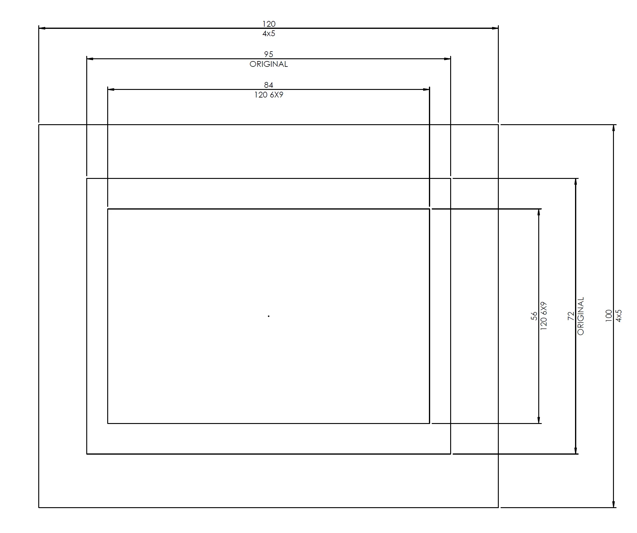
The frame lines in the 900 series viewfinder (which should be the same as the 110B) coincide very closely to the actual framing of a 120 6x9 negative. A 4X5 negative will be a much wider field of field that seems to closely associate with the edges of the visible area inside the viewfinder. After assembly, verify with your own copy. If you choose to add an accessory viewfinder, the horizontal field of view with the standard 127mm lens is ~38mm for 35mm/full frame equivalent.
Tools Required
range of small flat and phillips screw drivers
hex drivers
drill + drill bits
magnifying loupe
scissors/box cutter
Filament Selection
ABS-GF is my go-to for the vast majority of things. Durable, not very succeptable to moisture, heat resistant, and has a nice surface finish. The included 3mf file includes my print profile for it, once slowed down I found I get better top surfaces and overall print quality. You need to be careful to get the best bed adhesion as you can and let the parts cool before removing them from the build plate to prevent warp. It is designed in a way that the fasteners should pull out any warp that may occur but he tolerances for flatness are very tight for this project and significant warp can cause a loss in image quality. The 3mf file orients the parts in the intended print orientation.
Laser Cut Parts
The conversion is intended to use the laser cut slide locks. 3D printed versions are available but do not operate as smoothly or securely so while they work, I highly recommend sourcing the slides. I have a few spare sets if you'd like to purchase a prepped set. I personally used Sendcutsend and their design specifications but alternate suppliers are available. The slides should be made from .048" stainless steel, the included step files will not necessarily translate to other materials or thicknessess without adjustment. To purchase upload the included flat pattern step file. The part is too small for their finishing and bending operations without nesting/combining the parts. Once received you'll need to bend the ears (bend line should be 6-7mm from the end), deburr, and file/sand the bearing edge where it contacts the film backs to prevent damage to the backs.
Teardown and Preperation
Open the rear film chamber to access the inside. Fully tape off the lens and bellows across the film gate to protect them from metal shavings.
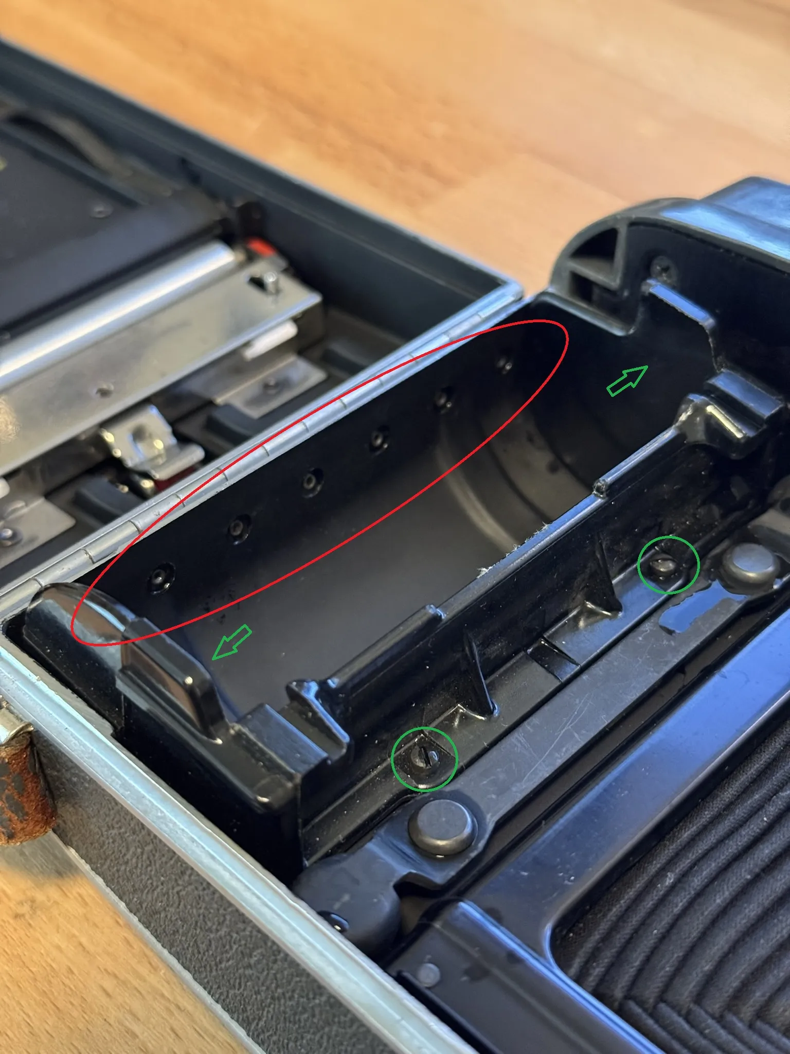
Drill or dremel off the rivet heads (red) for the hinges on the left side. Peel back the leatherette from the hinge carefully to fully separate the hinge and left door from the camera. Remove the two screws holding the film spool (green). Certain models have rivets through the top and bottom into the body (green arrows), if it is riveted you'll need to carefully drill out and/or pry on the film spool to remove it. After it is removed, drill out the two tapped holes to 1/8" thru holes. The leatherette over the hinge can be glued back down with contact cement or double sided tape.
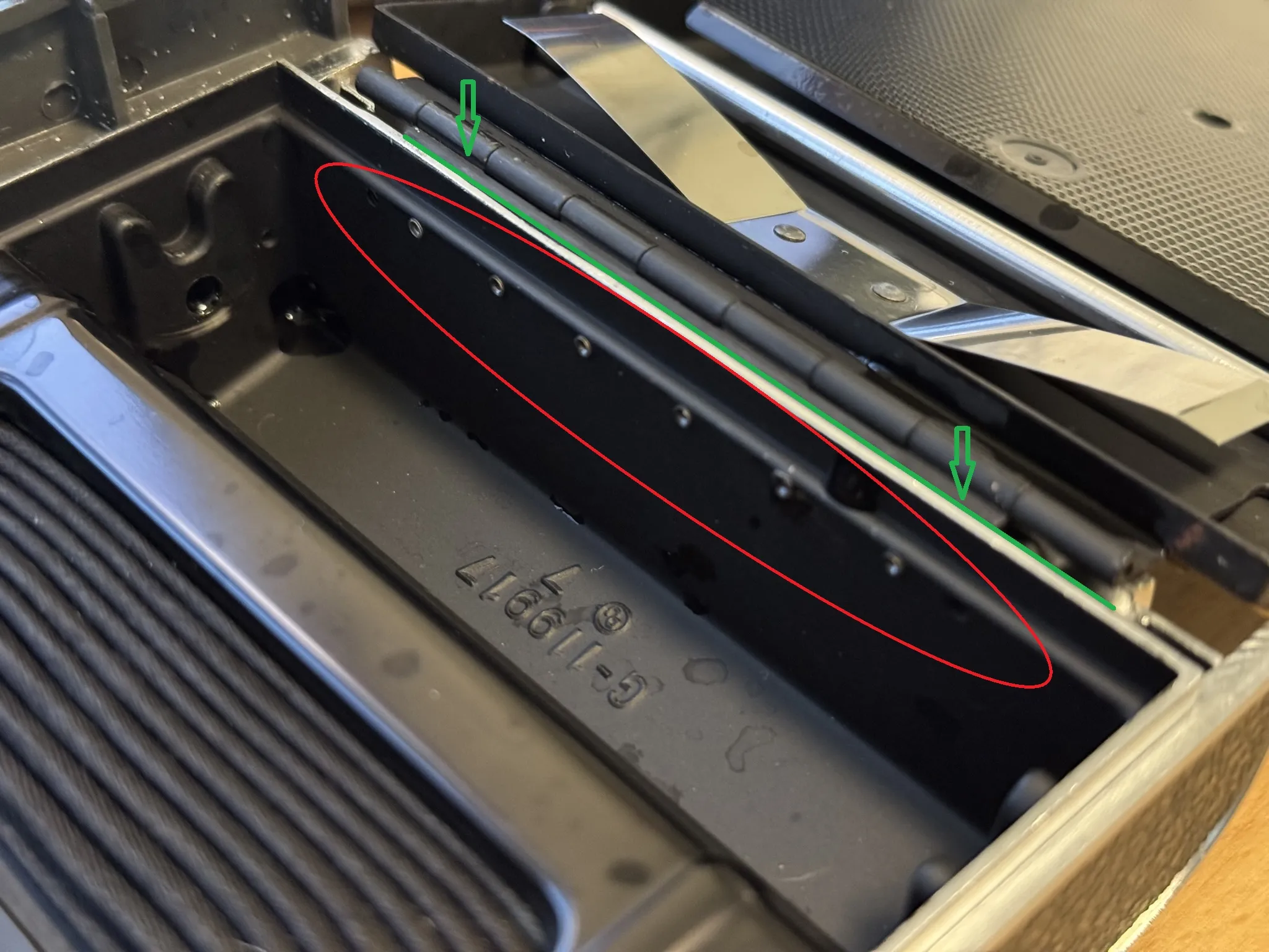
Drill or dremel off the rivet heads for the right side door. To remove this hinge, you may need to pry it away from the body along the green line using a small pry tool, be careful not to bend or tweak the camera body.
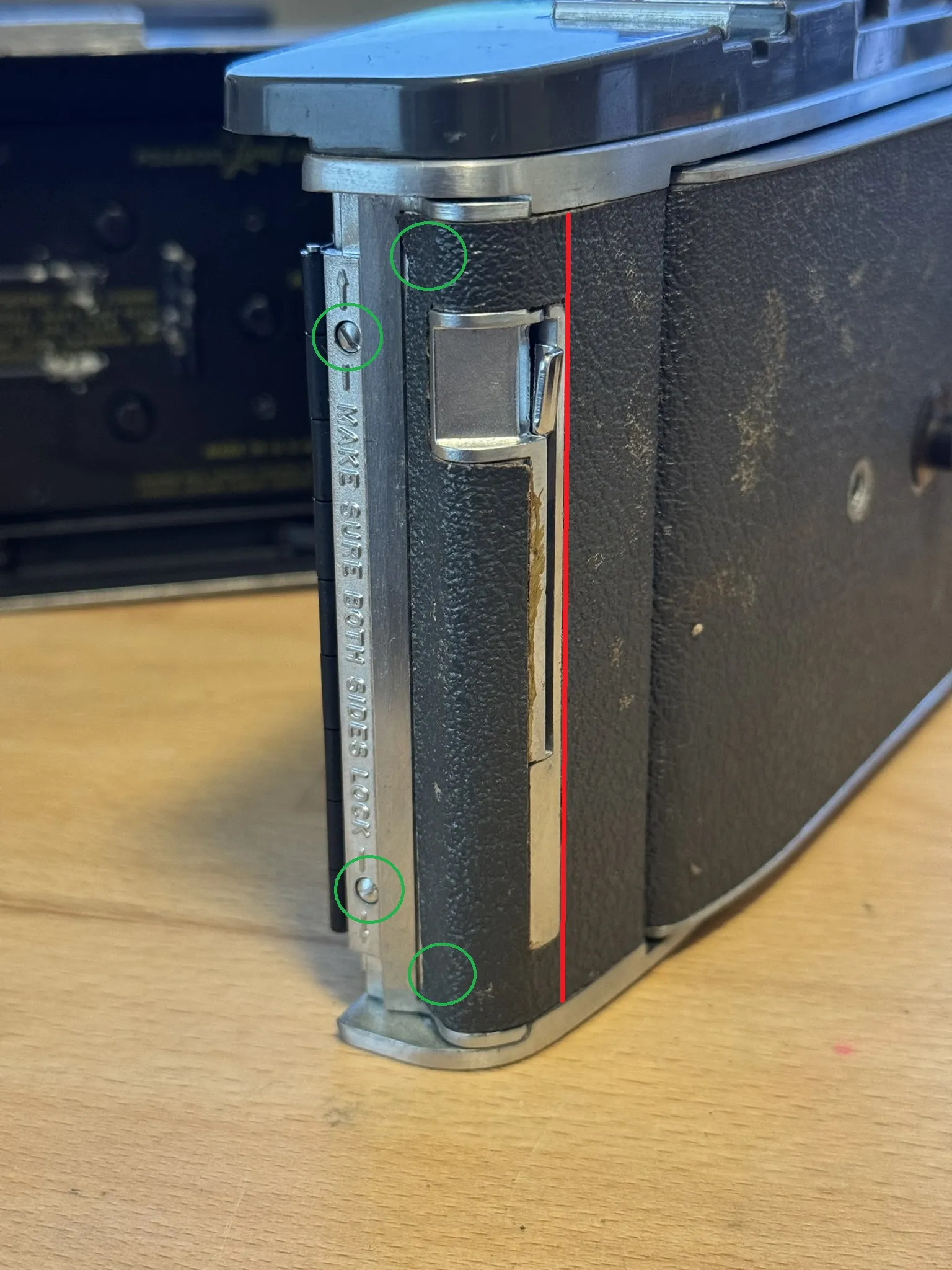
Cut the leatherette near the film door latch along the red line. Remove the leatherette to the left of this line to expose the latch plate and the two hidden fasteners underneath. Remove the four slotted screws retaining the latch plate and keep the screws for later use.
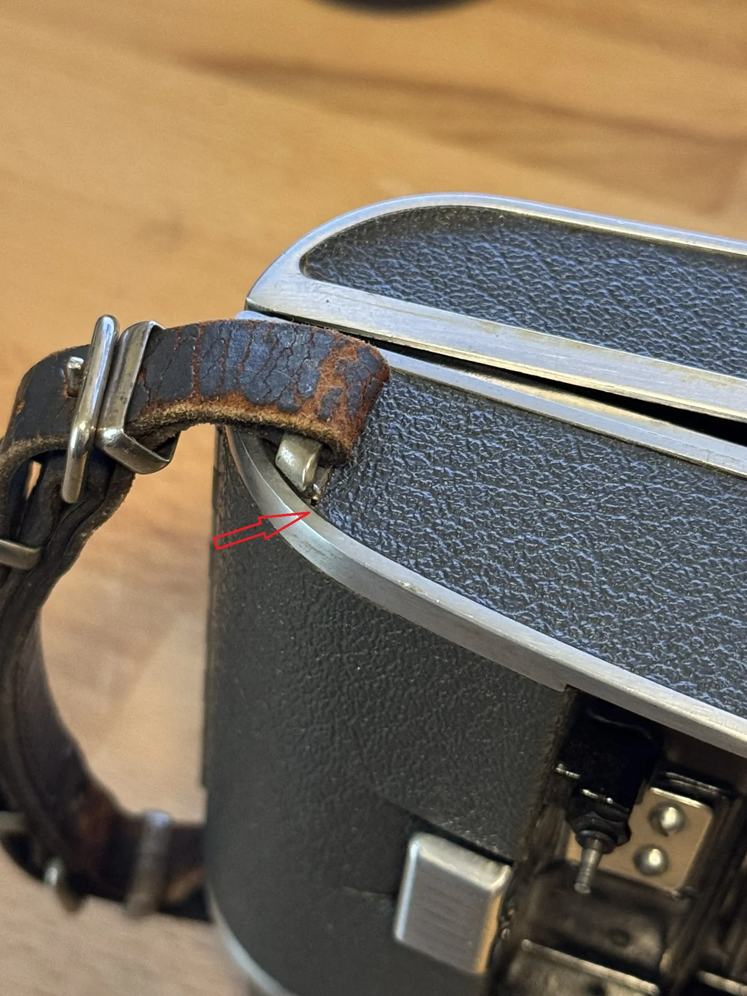
If you are omiting the side strap, lift the leatherette on the bottom in this area to acces the hidden strap lug screws and remove lower lug. This area will be covered by the new bottom plate. There is an alternate bottom plate with the cutout for the strap in the files.
Before you can add the conversion parts, the rangefinder should be adjusted. Set the focus to infinity and point the camera towards a large object in the distance, perferrably with distinct edges/features you can check against. Adjust the rangefinder mirror screws to correct any misalignment. See guides HERE for 110A or HERE for 110B/900 for top plate removal and rangefinder adjustment screw identification.
Reinstall top plate.
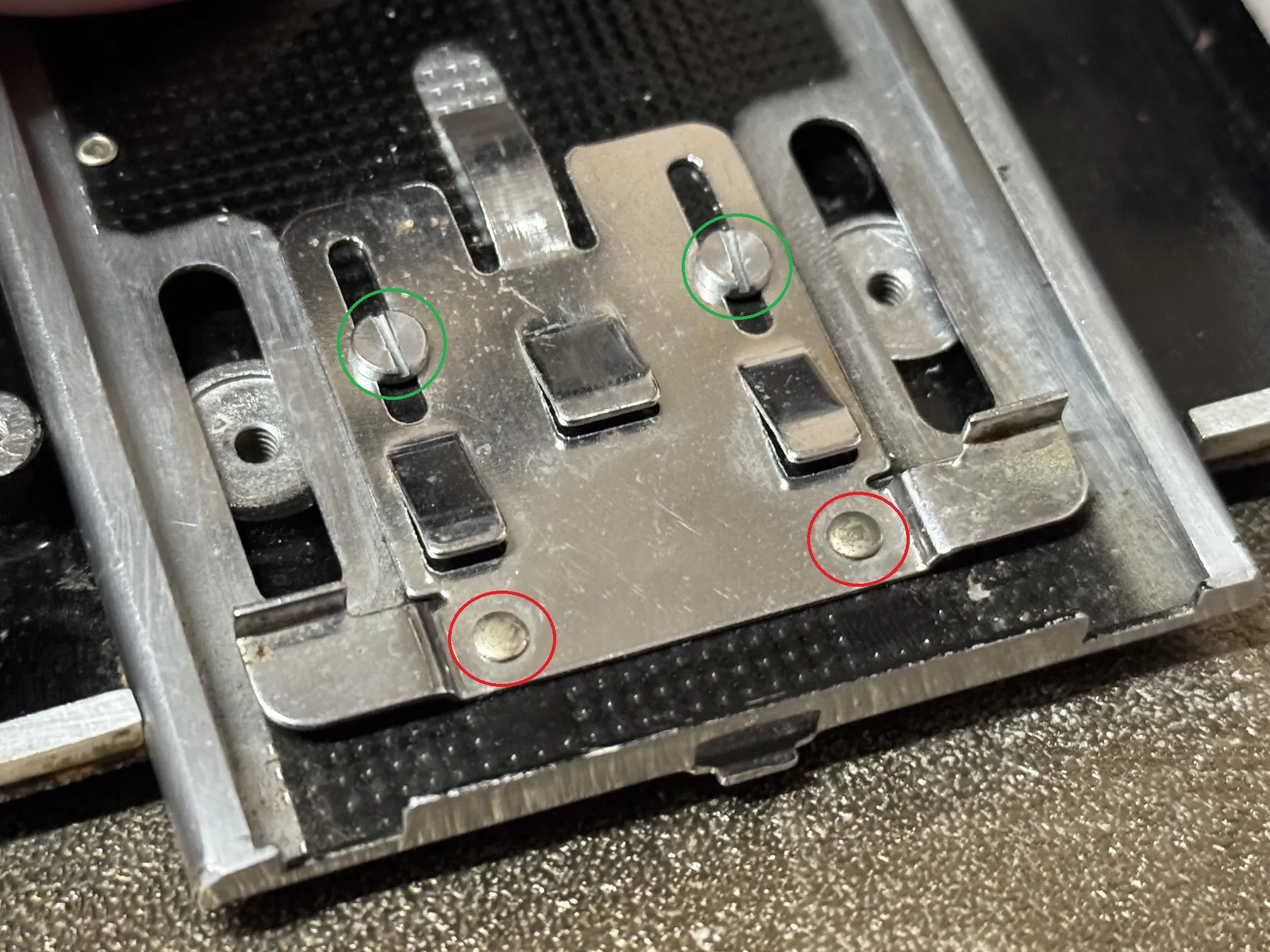
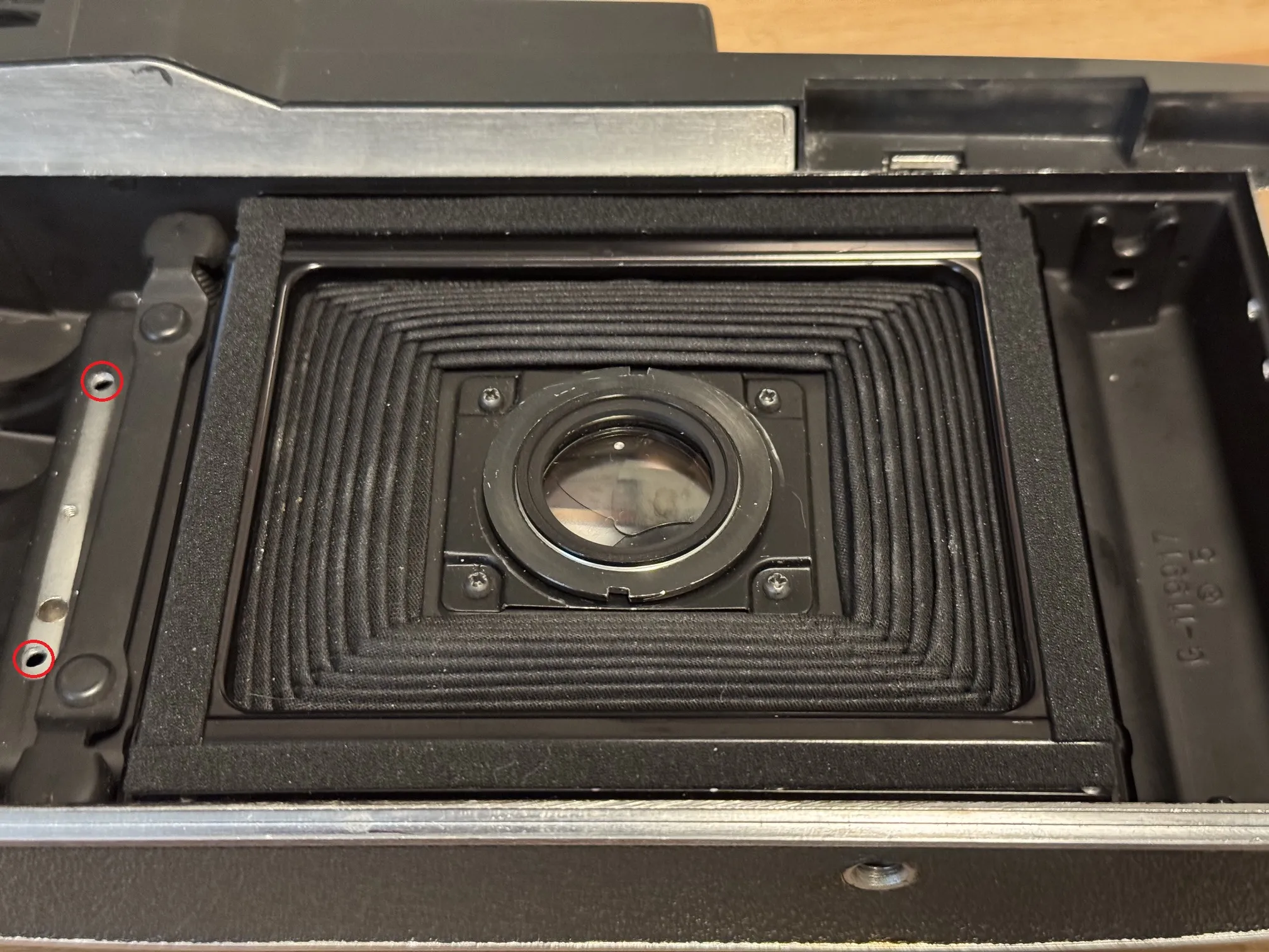
Drill out the two rivets (red) at the front of the stock lens stop/catch. Remove the two screws (green) to remove infinity stop and keep screws for later.
Bill of Material
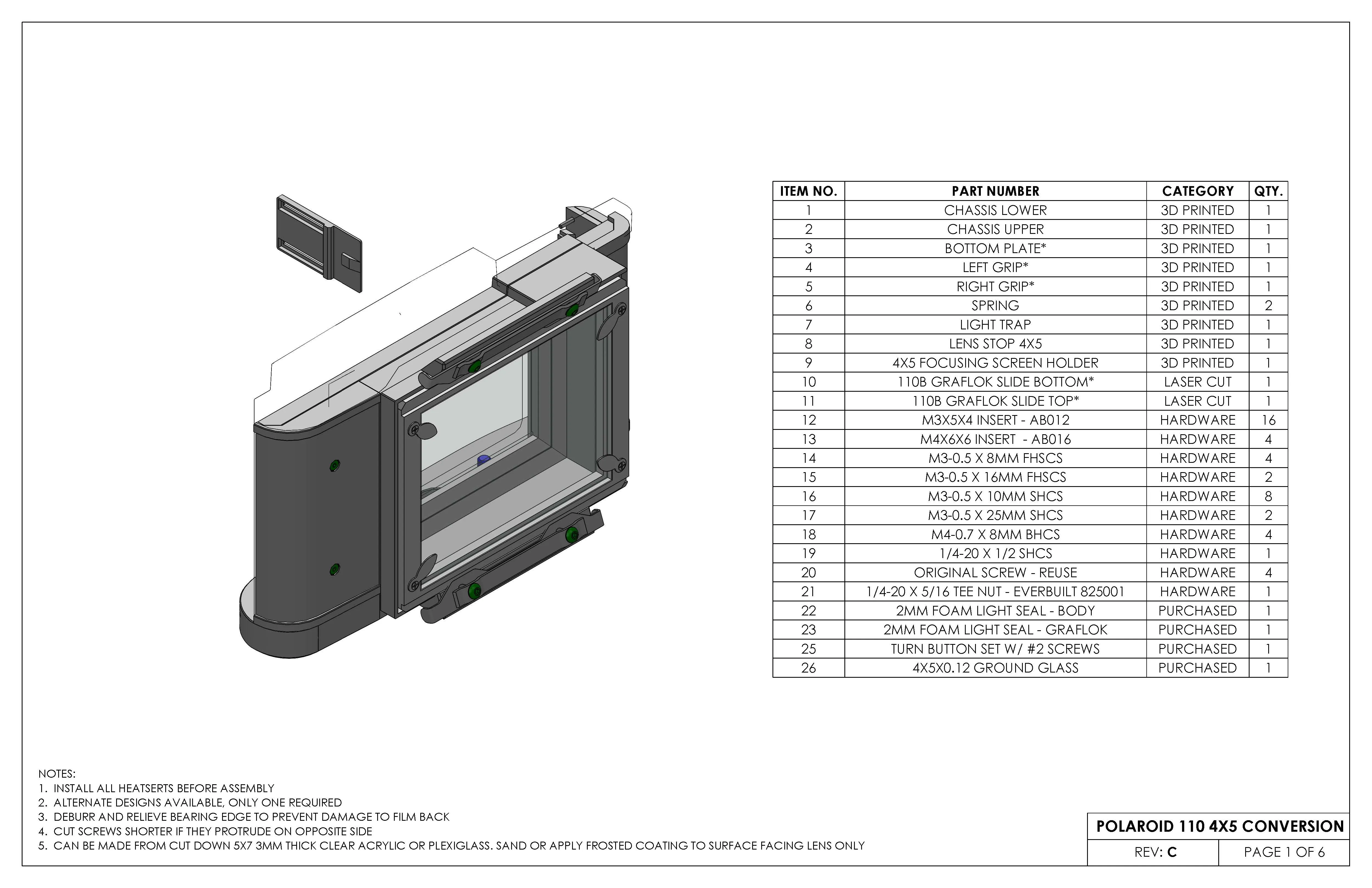
FHSCS = flat head socket cap screw
SHCS = socket head cap screw
BHCS = button head cap screw
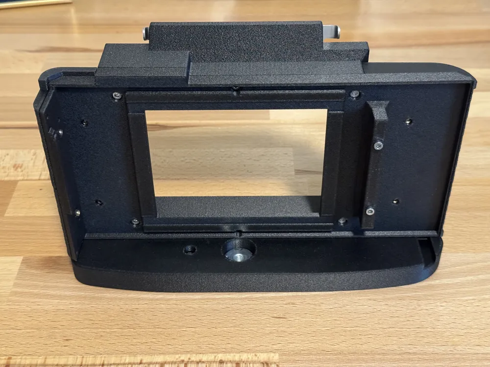
Chassis Assembly
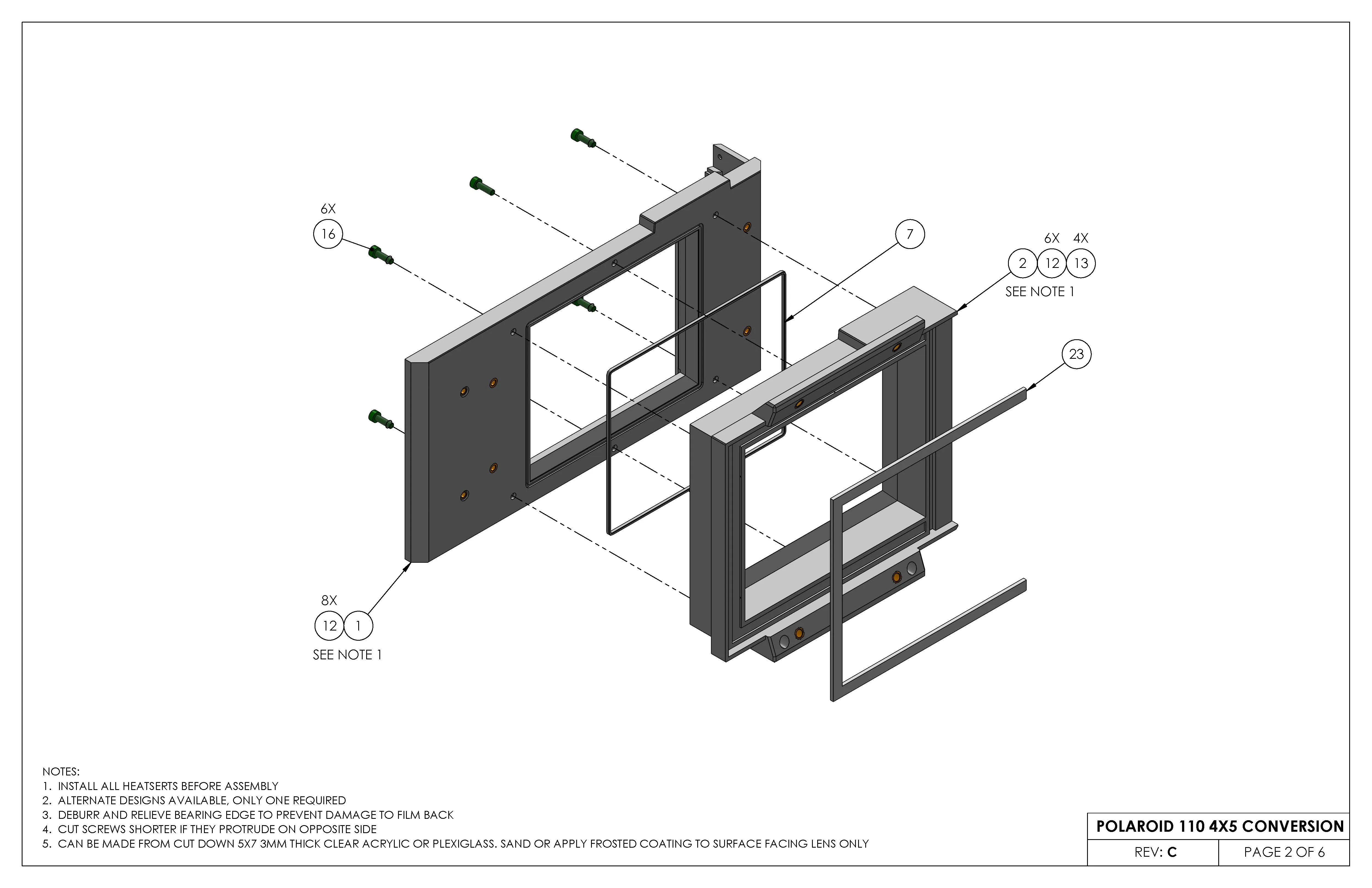
Chassis Mounting
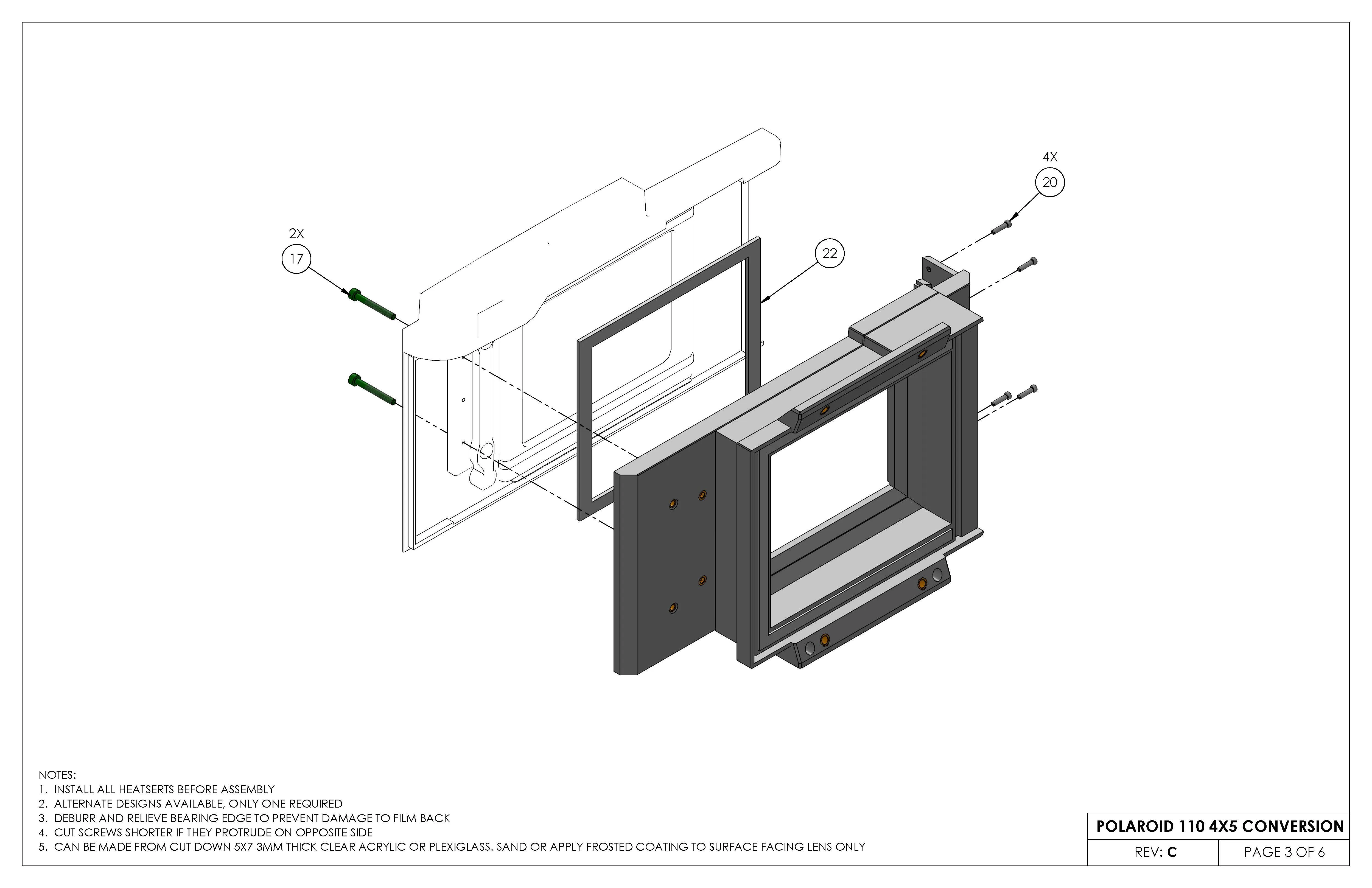
Installed light seal foam between body and conversion chassis - Item 20
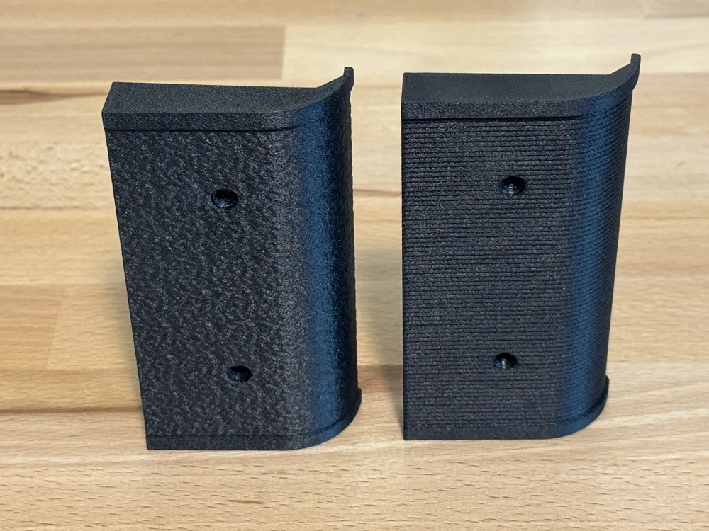
Grip and Bottom Plate Installation
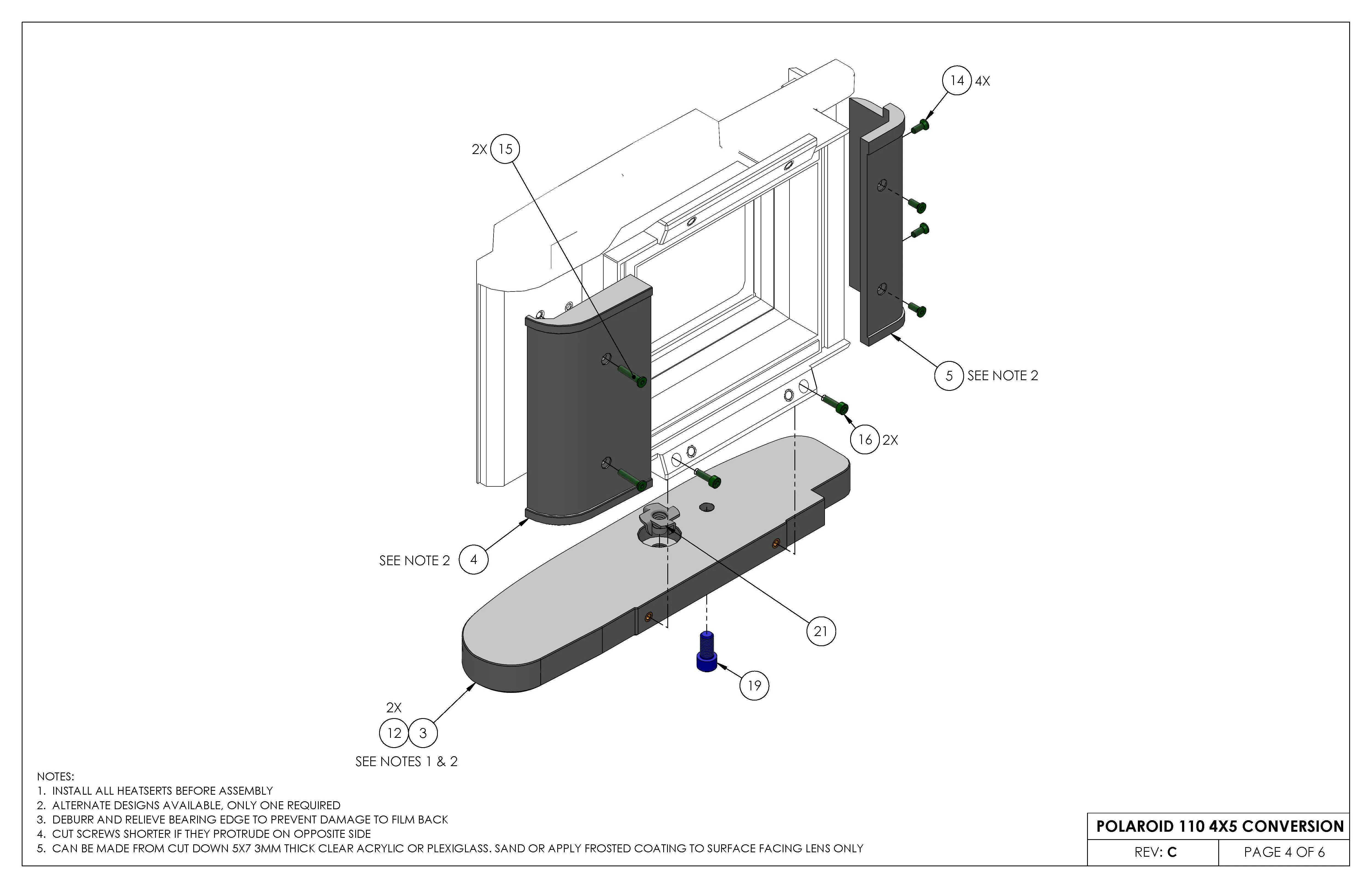
Alternate grip and bottom plate files are available
Graflok Locking Slide Assembly
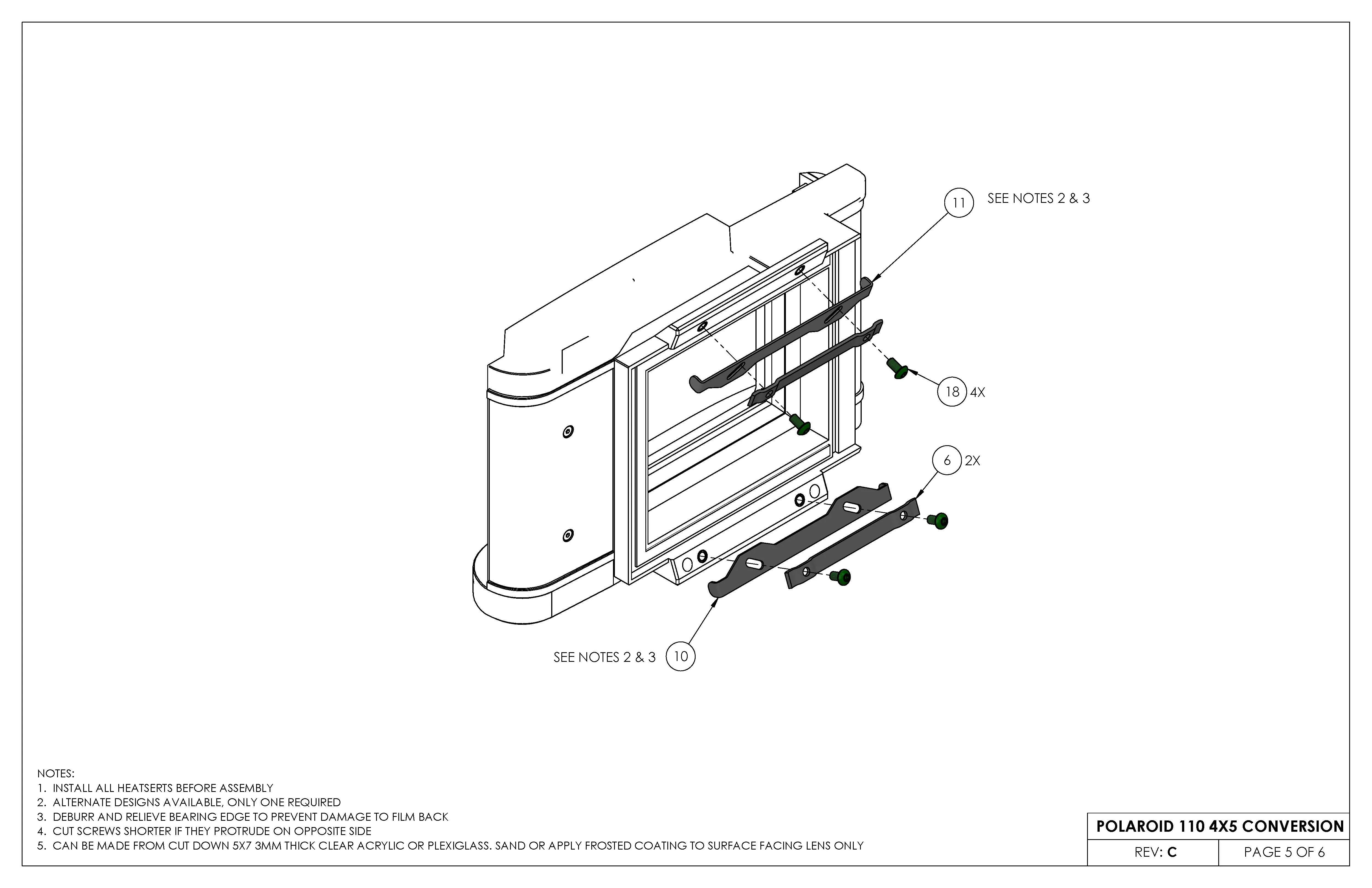
Adjust torque on screws (Item 16) to set slide resistance.
Ground Glass Holder Assembly
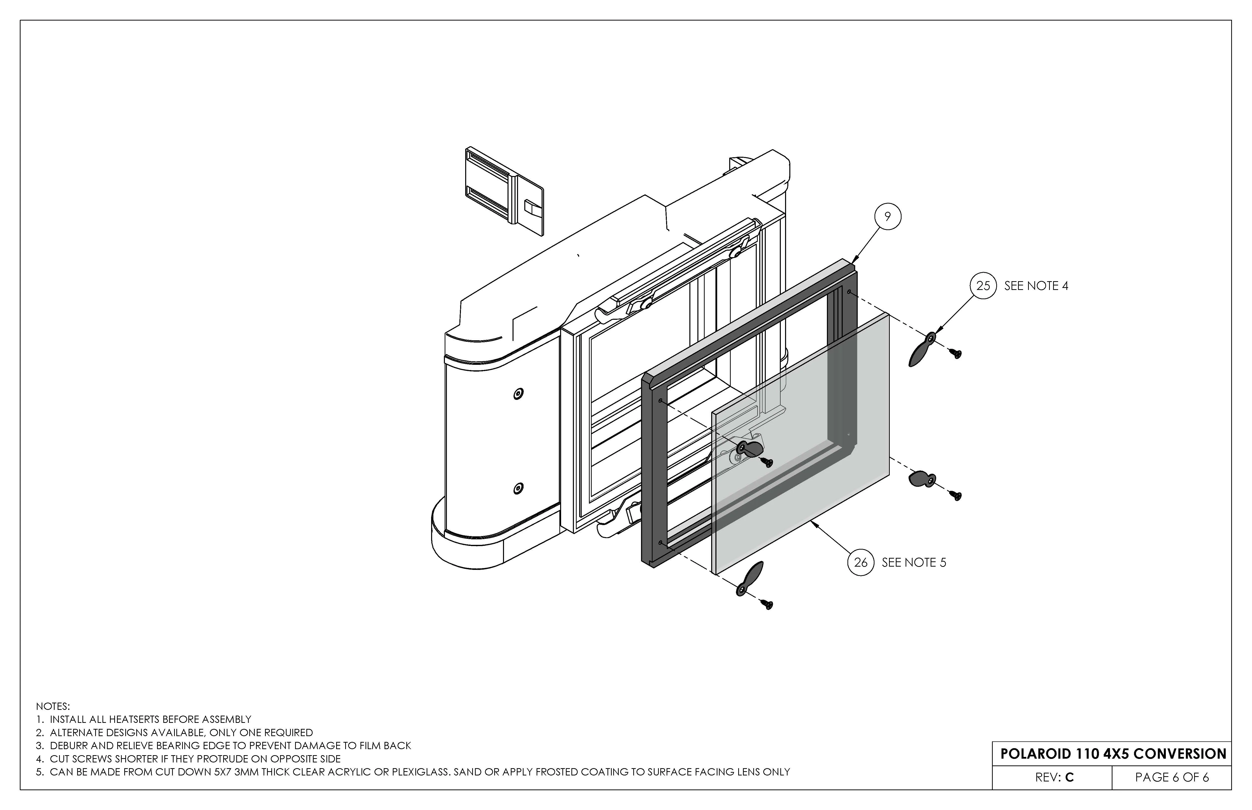
Holder is designed for a ground glass/focusing screen that is 4" x 5" x 3mm.This can be DIY'd by cutting it down from clear acrylic or plexiglass 5x7 frame glass replacement and sanding/grinding one surface to an even matte finish or by applying a frosted glass film or paint.
Matte surface needs to be installed towards the lens.
Final Calibration
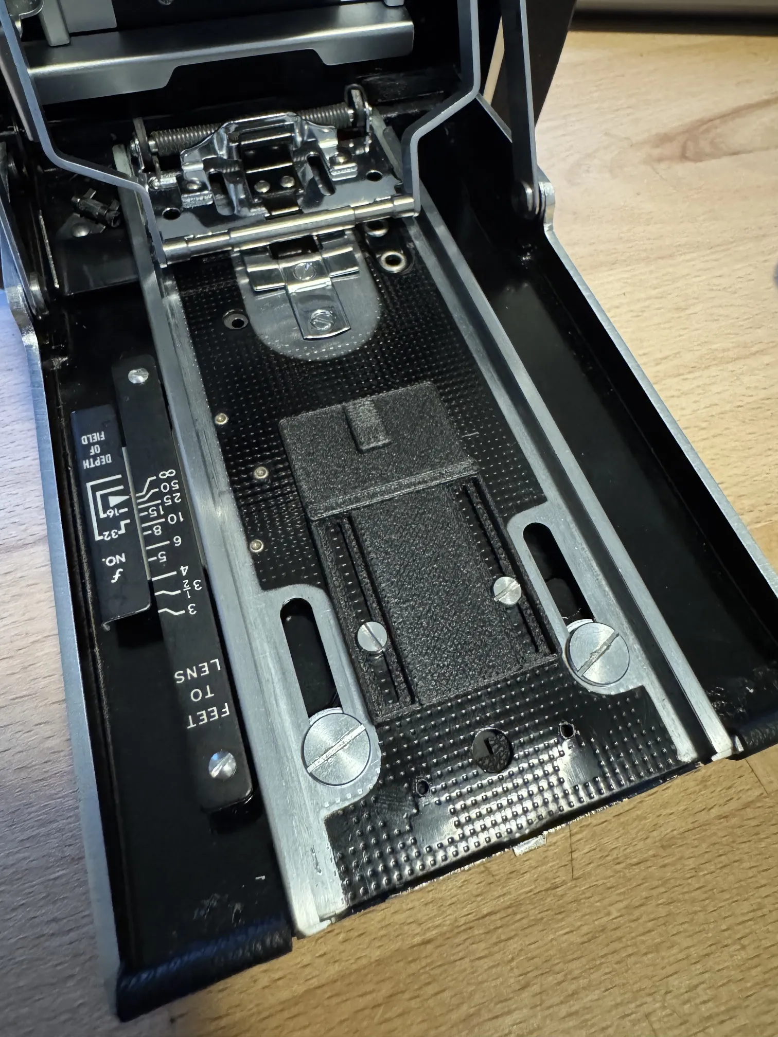
Once assembled, loosely install the new infinity stop using the original screws and fix ground glass holder back. If using an alternate focusing screen, the ground glass needs to be set back 5mm from the face of the graflok surface to match the film plane of standard holders. Verify the rangefinder is aligned at infinity, set the camera on a tripod and set up a focus target near by. Focus on the target with the rangefinder, hold the shutter open with a shutter release cable with the aperture wide open. Adjust the position of the lens stop until the focus target is sharp on the ground glass, verify with a high magnification loupe, and tighten screws. Check focus accuracy at minimum close focus and at infinity. If the focus is out of wack with the rangefinder, the round rangefinder cam under the top plate may need further adjustment.
References
This was the most direct influence on mine particularly around the graflok mount and spacing from the film place. This is a great option to use standard 2 sided 4x5 film holders and cleverly utilizes a cambo spring back.
Morten Kolve at film.kolve.org
Fantastic resource with conversion instructions and offers kits for sale. His design has better access particularly for the 110A viewfinder and overall is a more compact design at the tradeoff of off-center framing and not reaching full 4x5 coverage.
Albert Cornelissen at cornelissen.me
Another great resource, particularly for Lomograflok use. This is a nice compact solution for using the instax back and well documented. Has other published files for replacement top plates as well as his later projects like the MRF2 under the name Identidem Design.
Builder of instax conversions for multiple cameras including roll film polaroids. Super nice guy.
Builder of 4x5 conversions and a great inspiration for well done conversions
Revision Log
Rev B - Updated photos and assembly drawings
Rev C - Added ground glass holder and associated parts to BOM, added additional alternate bottom plate, revised assembly drawings
License



Comment & Rating (0)