
Variable Bench Power Supply — DIY Enclosure - 90W

Print Profile(1)
Bill of Materials




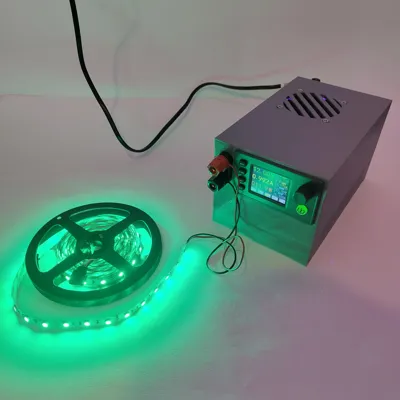
- Optional 12V LED strip x 1:
- M5 Fan screws x 1: Regular PC fan screws
- Powercord with C8 Male connector x 1:
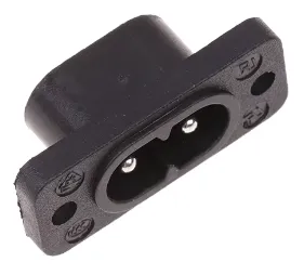
- 8-shaped (C8) AC inlet socket x 1: Female connector
- 18 AWG DC wire x 1:
- 60 mm 12 V fan x 1: ball-bearing recommended
- Banana jacks (female) with mounting hardware x 1: Standard size
- Internal PSU: 12 V DC, 10 A, 120 W (220 V AC in, EU plug) x 1: https://s.click.aliexpress.com/e/_DBfnvRD
- DC-DC buck-boost converter with color display — model SK90C (0.5–36 V, up to 90 W) x 1: Find it on AliExpress
Description
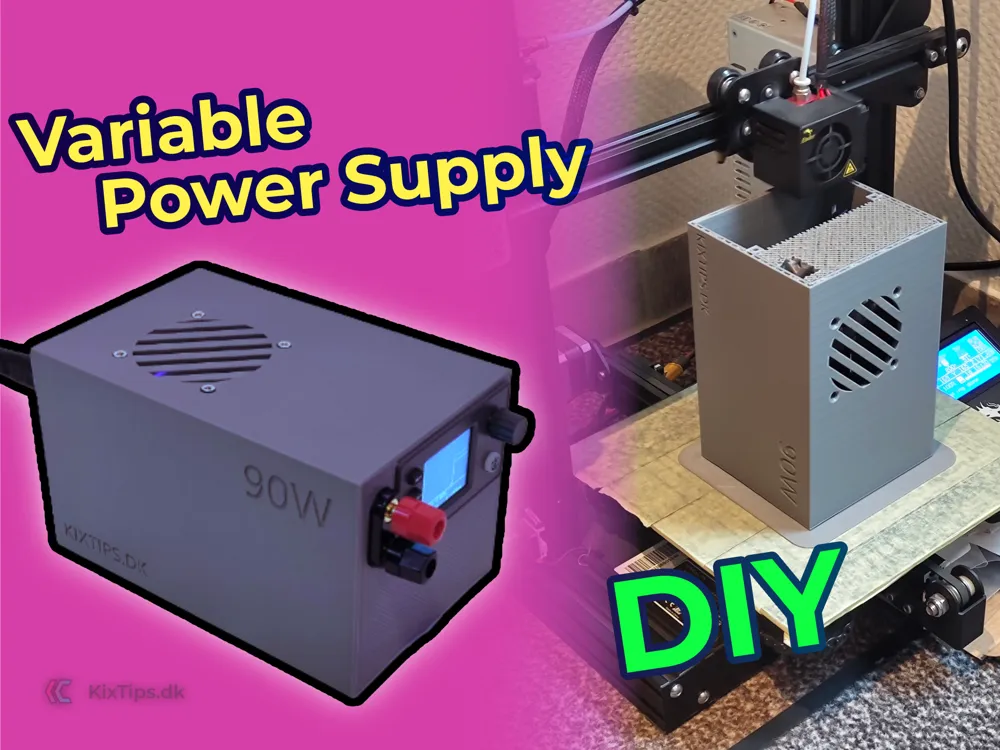
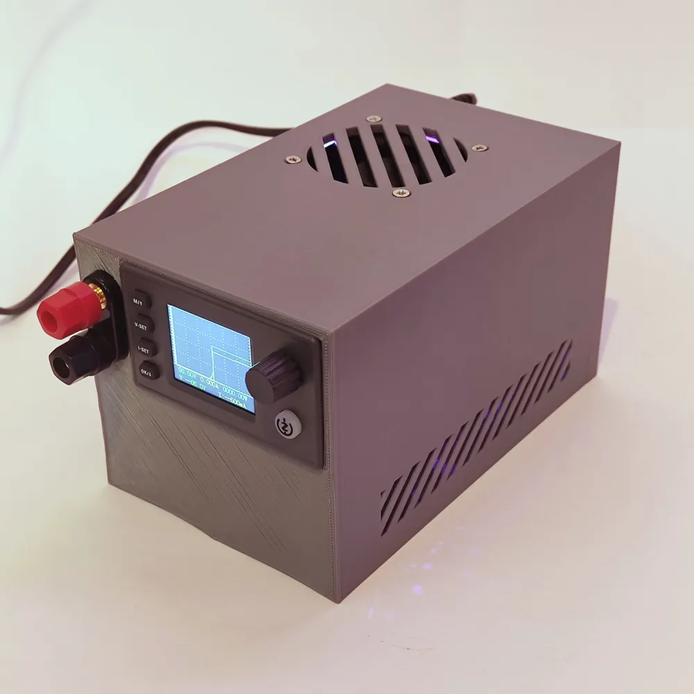
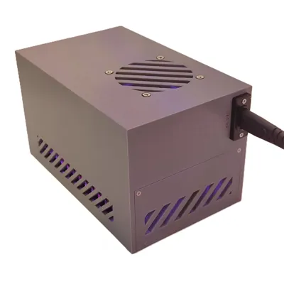
A real bench power supply you build yourself
Every electronics hobbyist eventually hits the same wall: you need a specific voltage to test an LED strip, revive an old PC board, or bench a circuit — and you don't have a supply that delivers exactly that. I designed Kixtips' Variable Power Supply to solve this. It houses an adjustable buck-boost converter and an internal AC/DC supply inside one tidy, modern enclosure that looks at home on a workbench instead of being a loose pile of modules and exposed mains wiring.
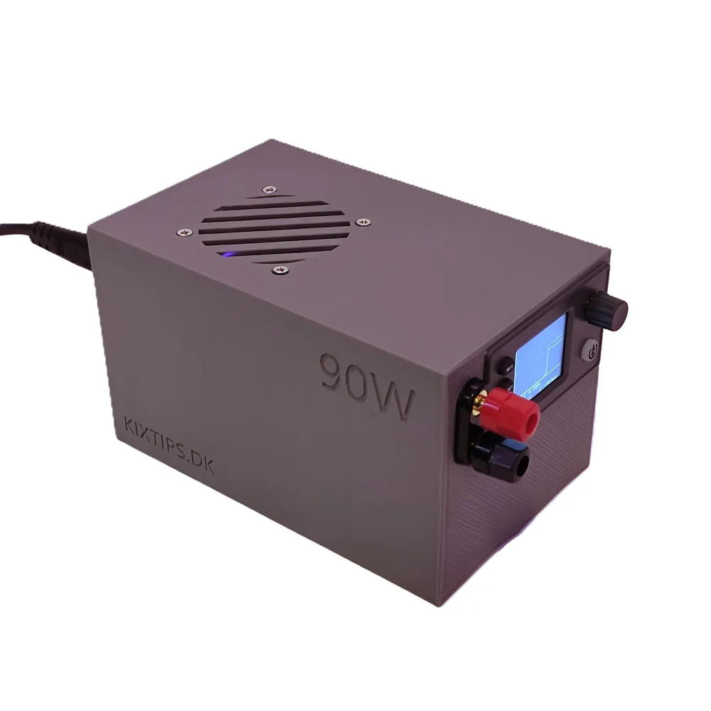
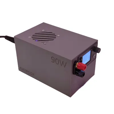
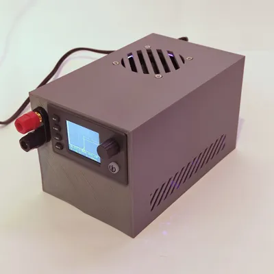
This is the enclosure + complete build. You print two parts, follow the wiring diagram, and assemble a fully functional variable supply with a color display, front banana terminals, and active cooling.
What it does
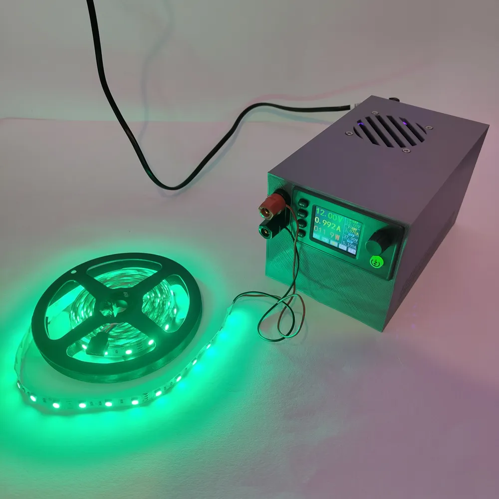
- Output: 0.5–36 V adjustable, 0–5 A, up to 90 W (driven by an SK90C DC-DC buck-boost module with color display)
- Live readout of voltage, current and power, plus adjustable max limits for voltage and current (handy when feeding something you don't want to cook)
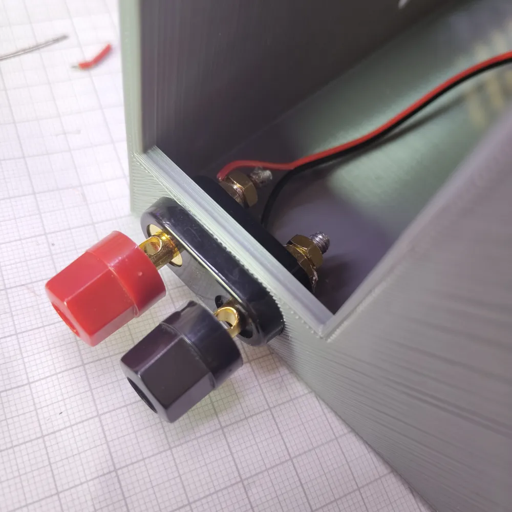
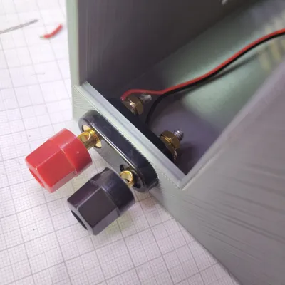
- Front banana jacks (+ / GND) — unscrew the caps to also clamp bare wires
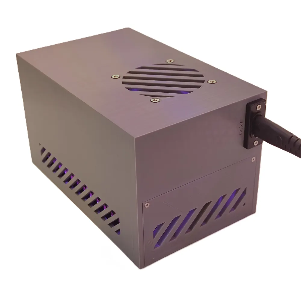
- Standard AC inlet: just plug in a normal power cable
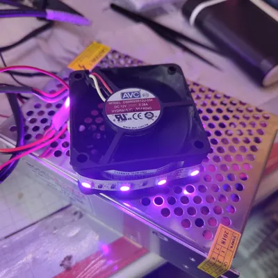
- Quiet 60 mm fan keeps the internal PSU cool during longer, higher-load use
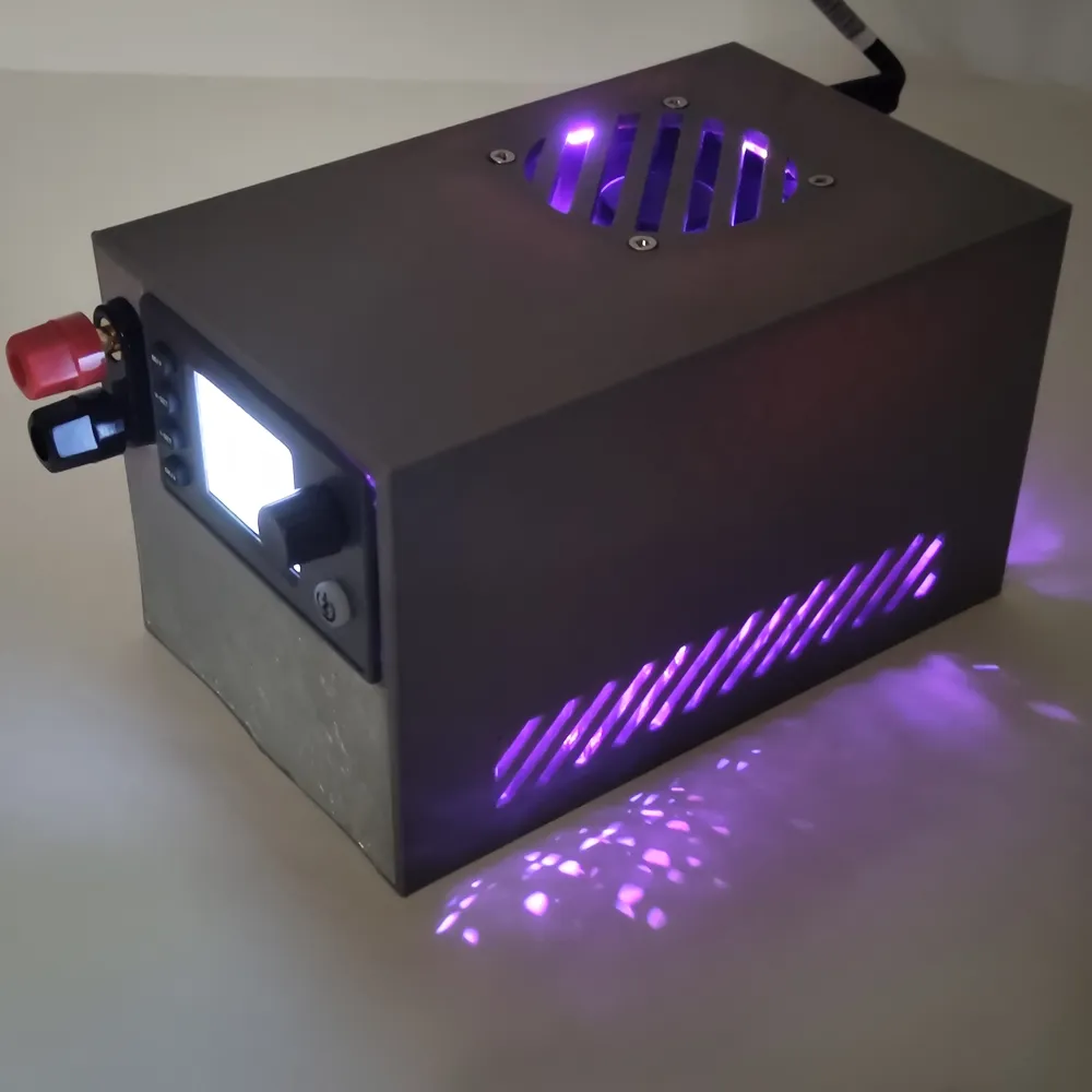
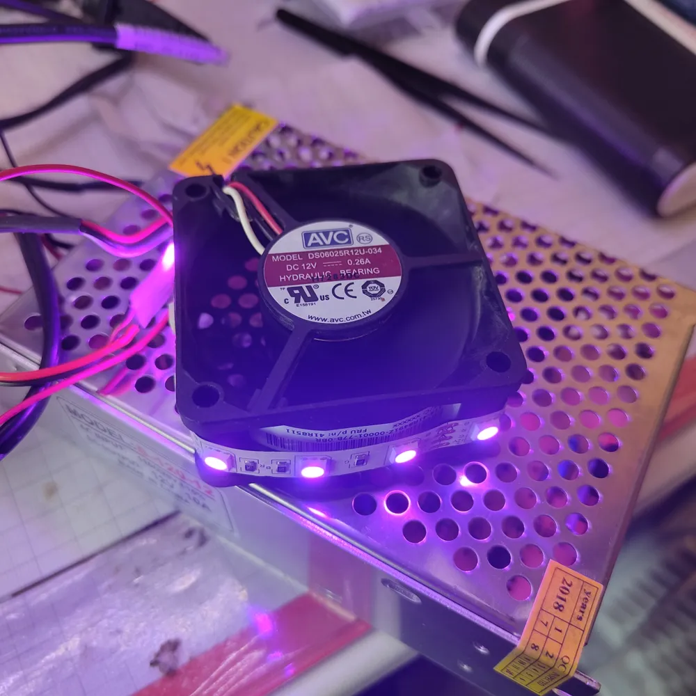
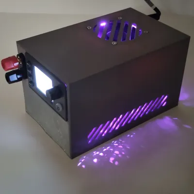
- Optional internal LED strip for a nice glow through the vents
Specifications
Enclosure (printed): 17.5 cm deep × 11.0 cm wide × 10.4 cm tall
Output (SK90C module): 0.5–36 V (±0.3%), 0–5 A (±0.5%), max 90 W; resolution 0.01 V / 0.001 A
Internal PSU: 220 V AC in → 12 V DC out, 10 A, 120 W (EU plug; see notes for non-EU / US 110 V)
Cooling: 60 mm 12 V fan (ball-bearing recommended)
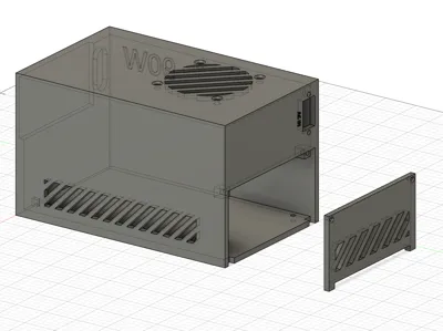
Parts: 2 printed parts — main enclosure + mounting bracket/lid
Why two printed parts
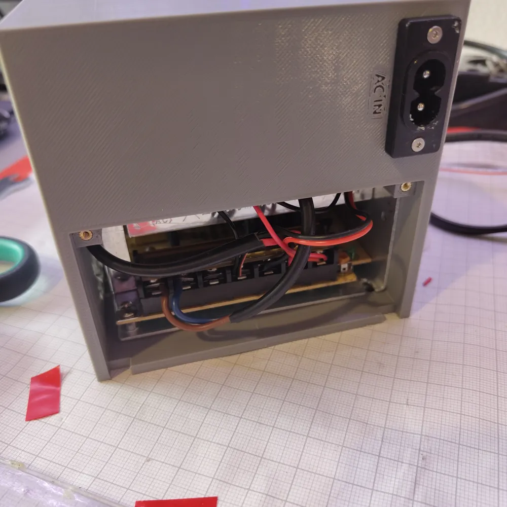
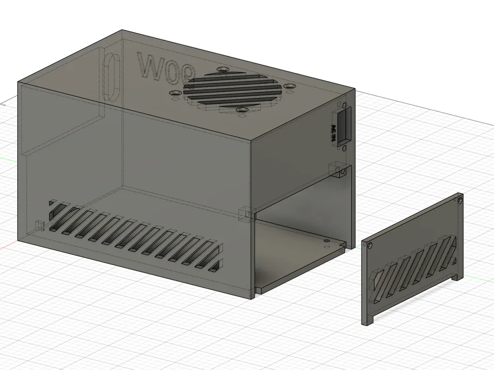
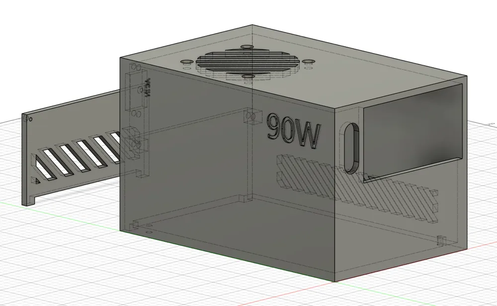
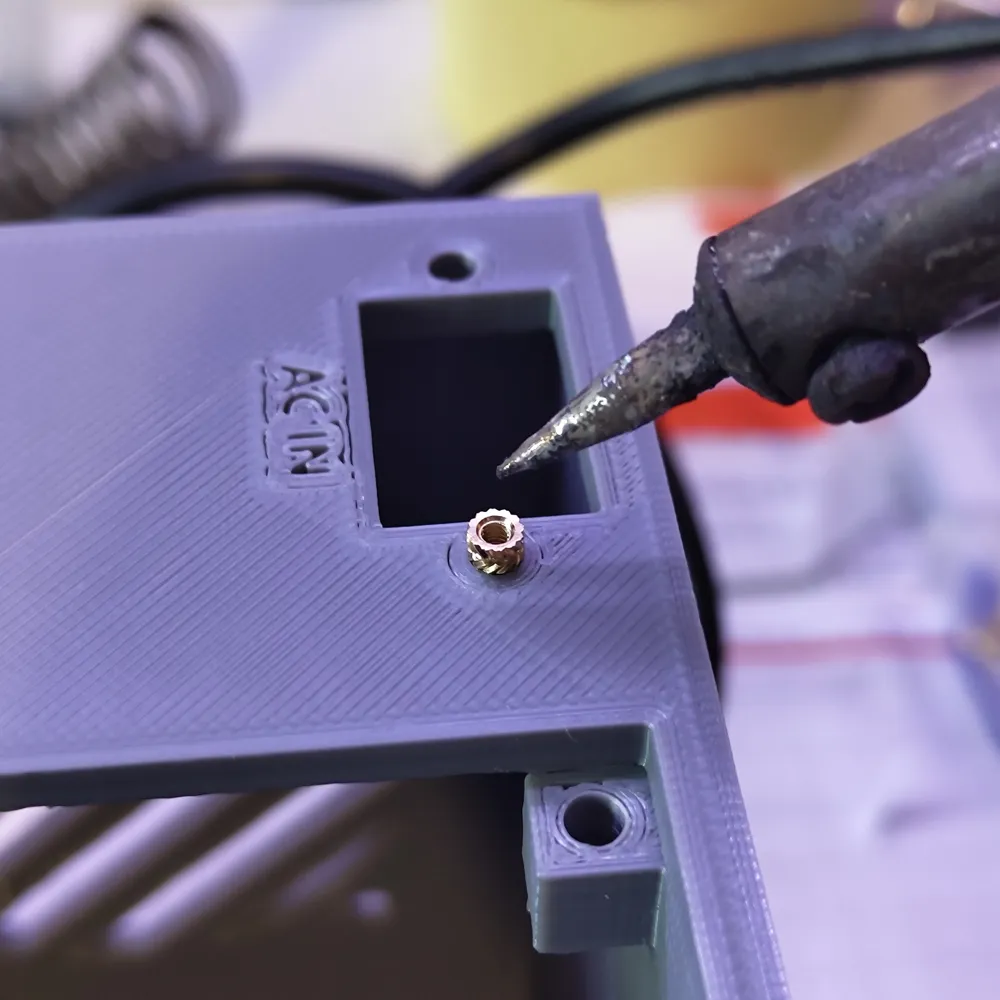
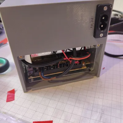
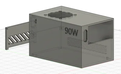
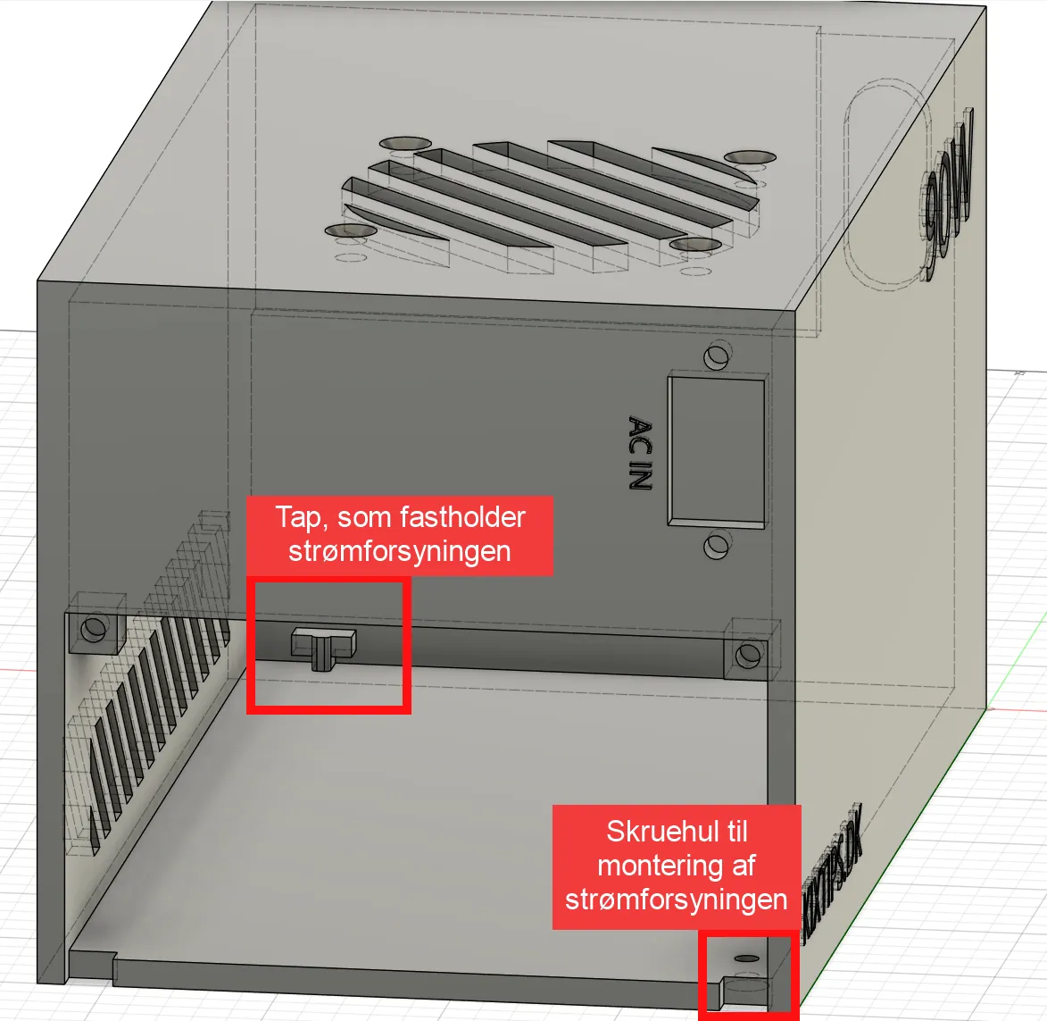
The enclosure has built-in cut-outs for cooling, the AC inlet, the converter module and the banana jacks, plus an internal tab the PSU slides onto so it locks in securely. The separate bracket holds everything closed and the PSU fixed. Screw inserts give clean, reusable metal threads instead of self-tapping into plastic.
Print profile (recommended)
- Material: Matte PLA or Basic PLA (Gray looks great)
- Nozzle: 0.4 mm
- Layer height: 0.2 mm
- Infill: 20% minimum
- Supports: Tree
- Bed adhesion: none needed — with dried filament and a well-tuned bed I get no warping, so no raft or brim. (The model was *originally* printed with raft/brim before I dried my filament; you only need them if you see warping.)
- Orientation: print the enclosure FRONT-FACE DOWN for the cleanest visible surfaces
Two plate options in this profile
This profile includes two prepared plates so you can choose your cleanup-vs-reliability trade-off:
- Plate 1 — full support around the vents: safest, cleanest result for the vent area.
- Plate 2 — no support around the vents: the small overhangs in the ventilation slots are non-critical and print fine without support, saving filament and cleanup.
Pick whichever suits your printer; both produce the same finished part.
Boost Me (for free)
Help me support this project by Boosting! :)
Assembly (overview)
1. Trim parts and remove supports.
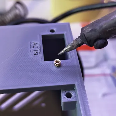
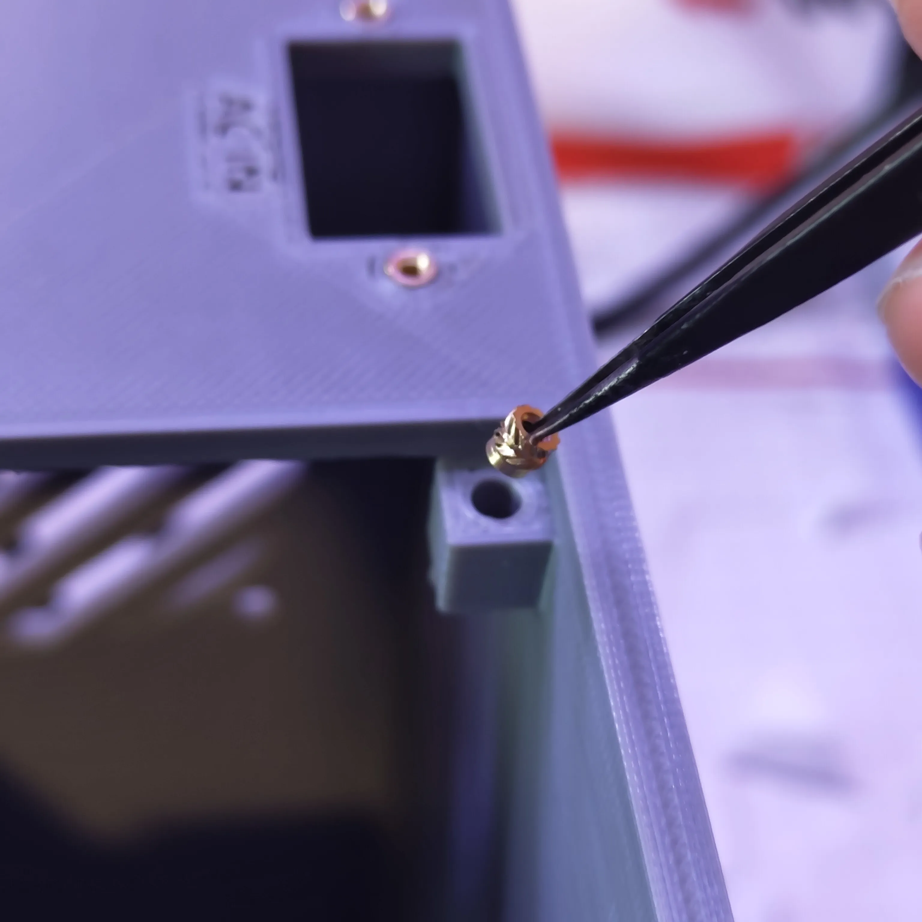
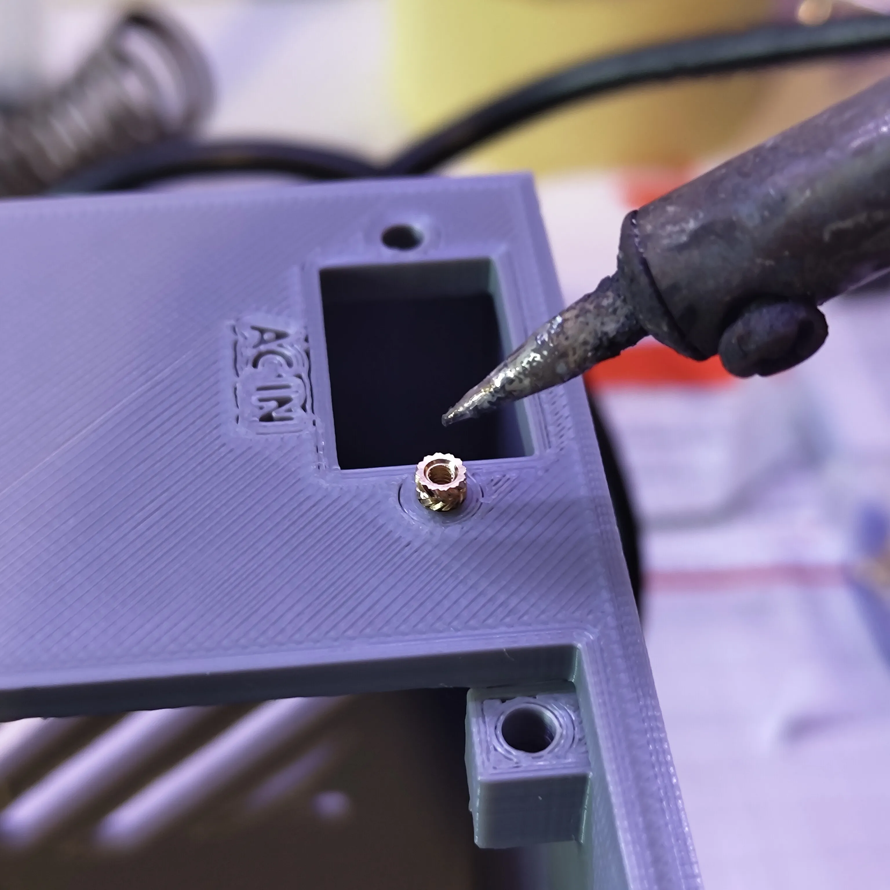
2. Heat-set the four M2 brass inserts with a soldering iron, flush to the surface.
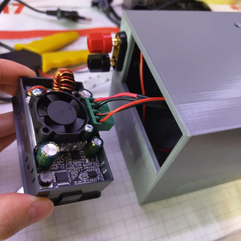
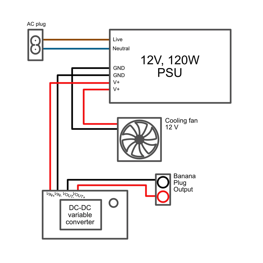
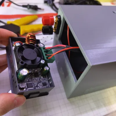
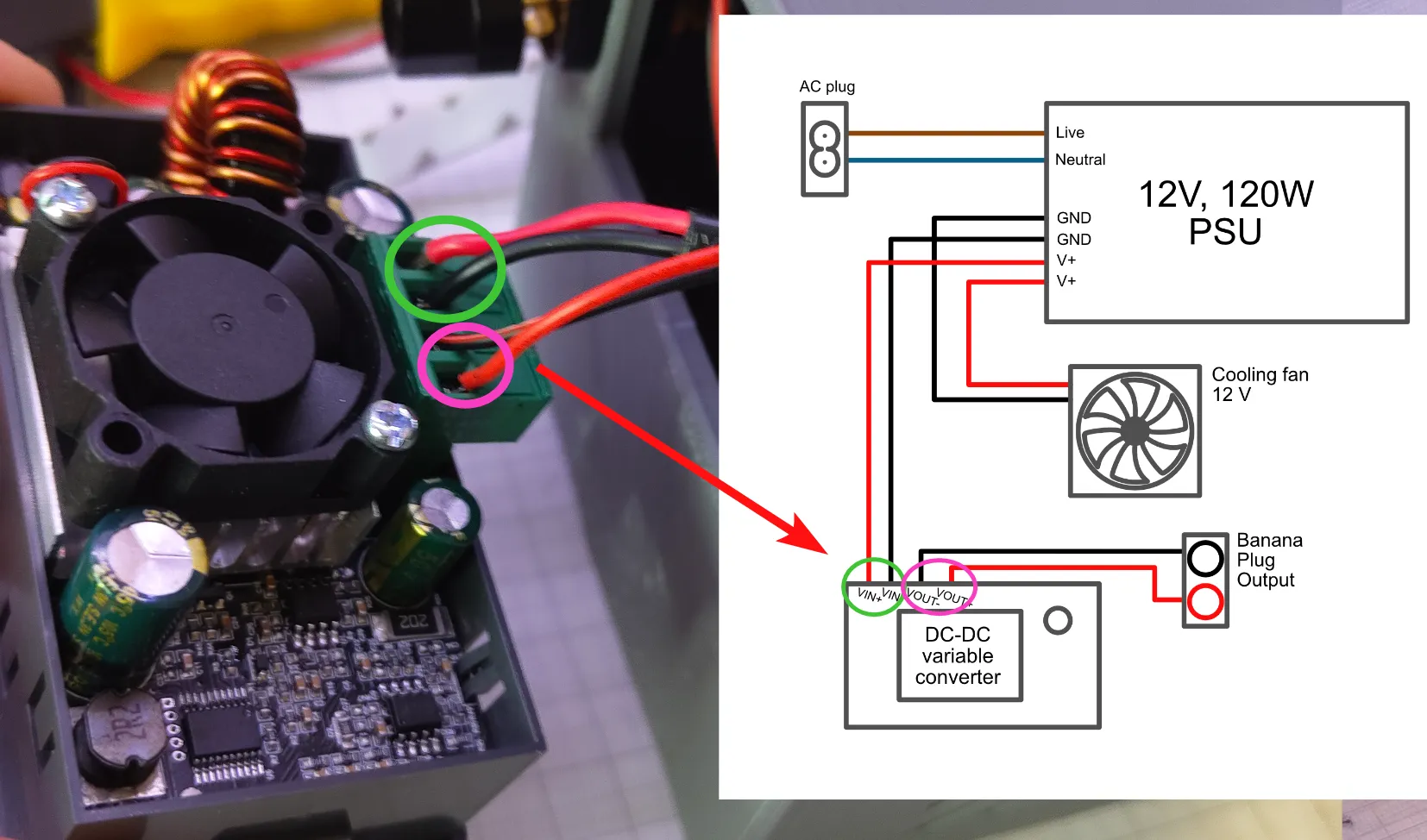
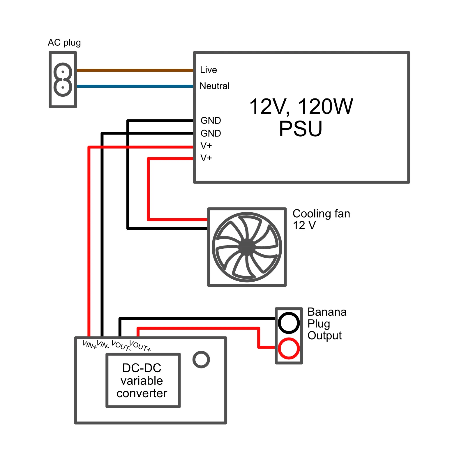
3. Wire the converter's green terminal: VIN+ / VIN- go to the PSU later; VOUT+ / VOUT- go to the banana jacks.
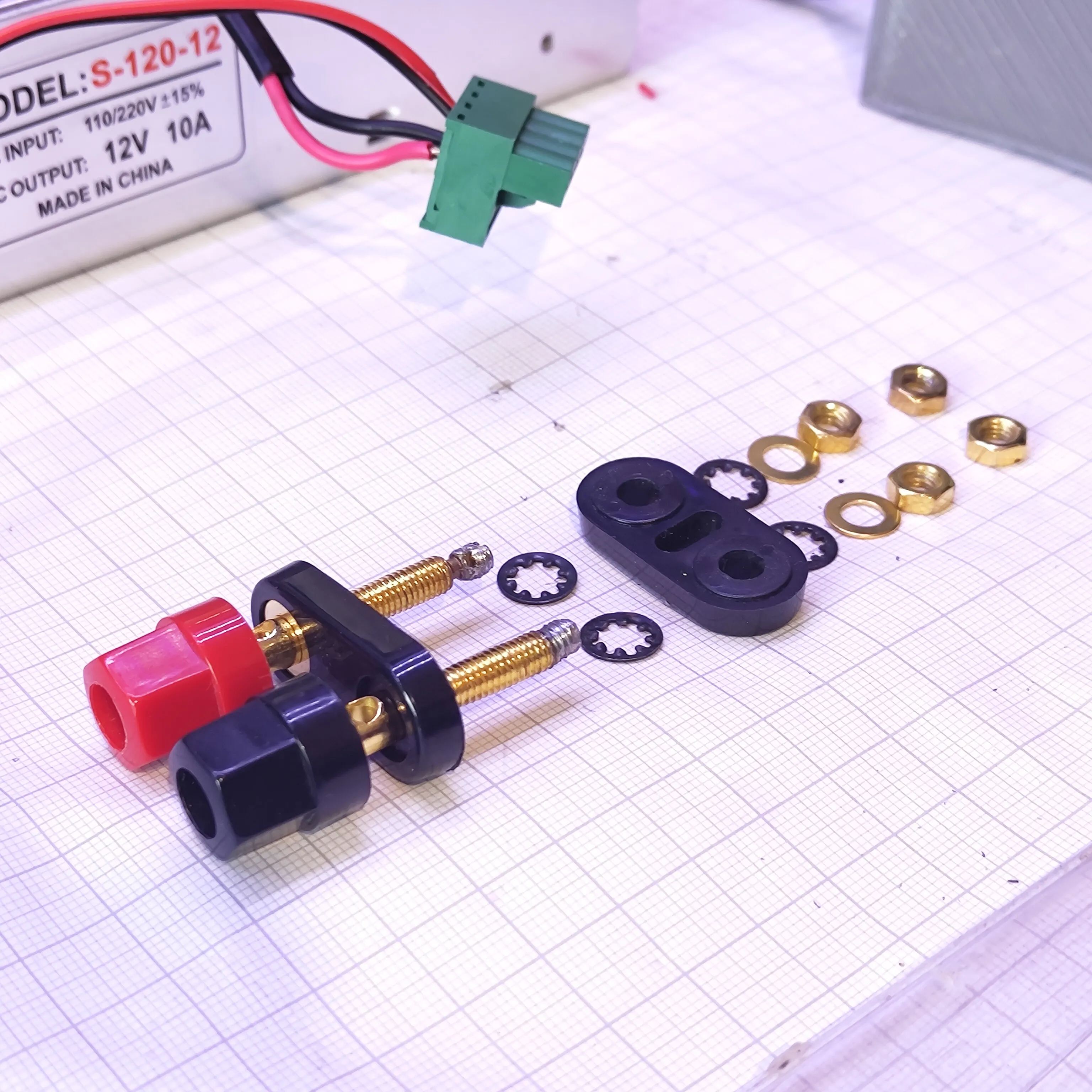
4. Mount the banana jacks, wrap and tighten VOUT wires to the correct posts.
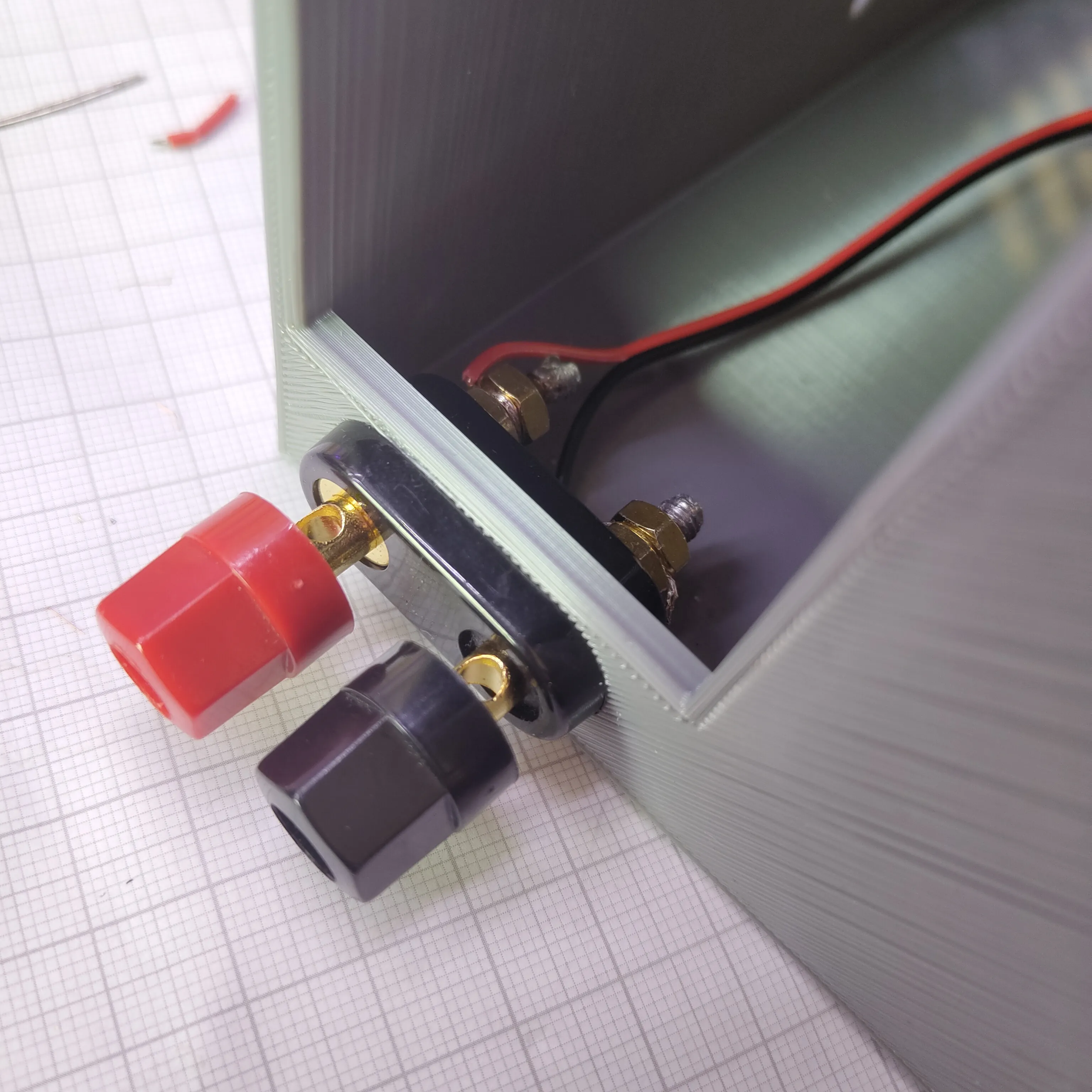
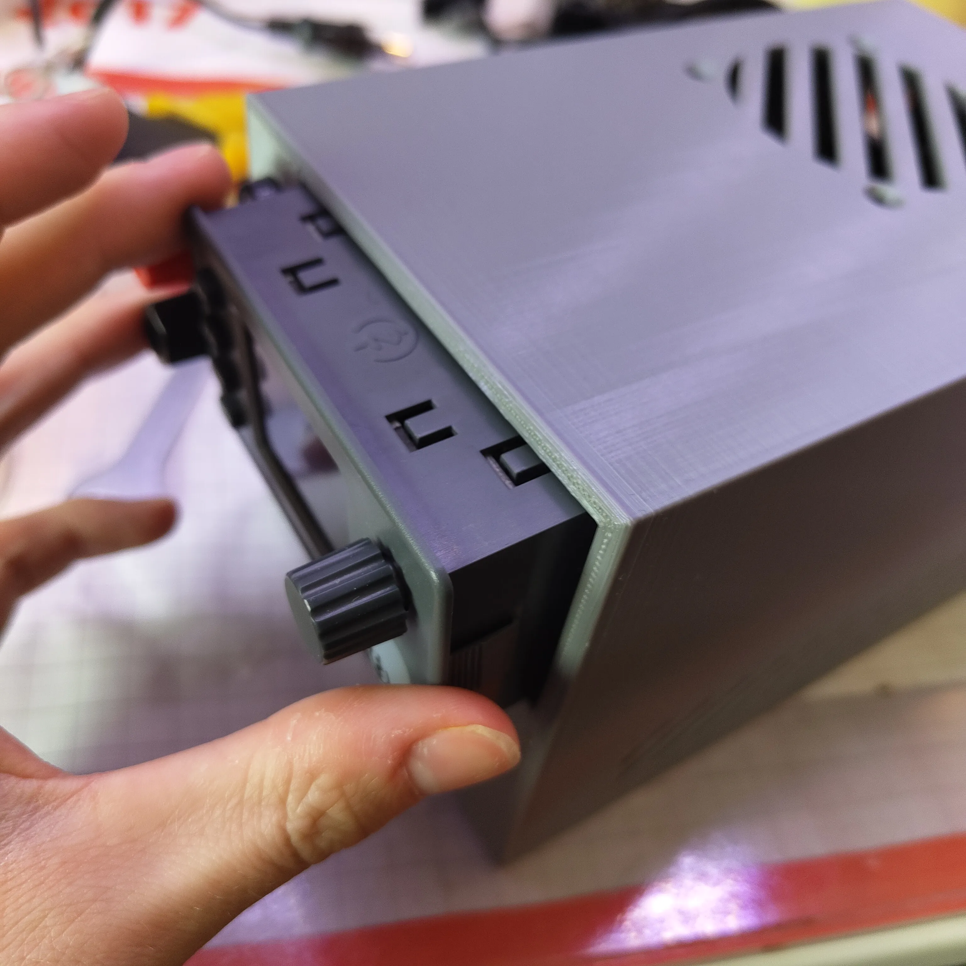
5. Click the converter module into its cut-out (add a strip of tape inside the edge if it needs more friction).
6. (Optional) Mount a short LED strip around the fan, wired to +12 V / GND.
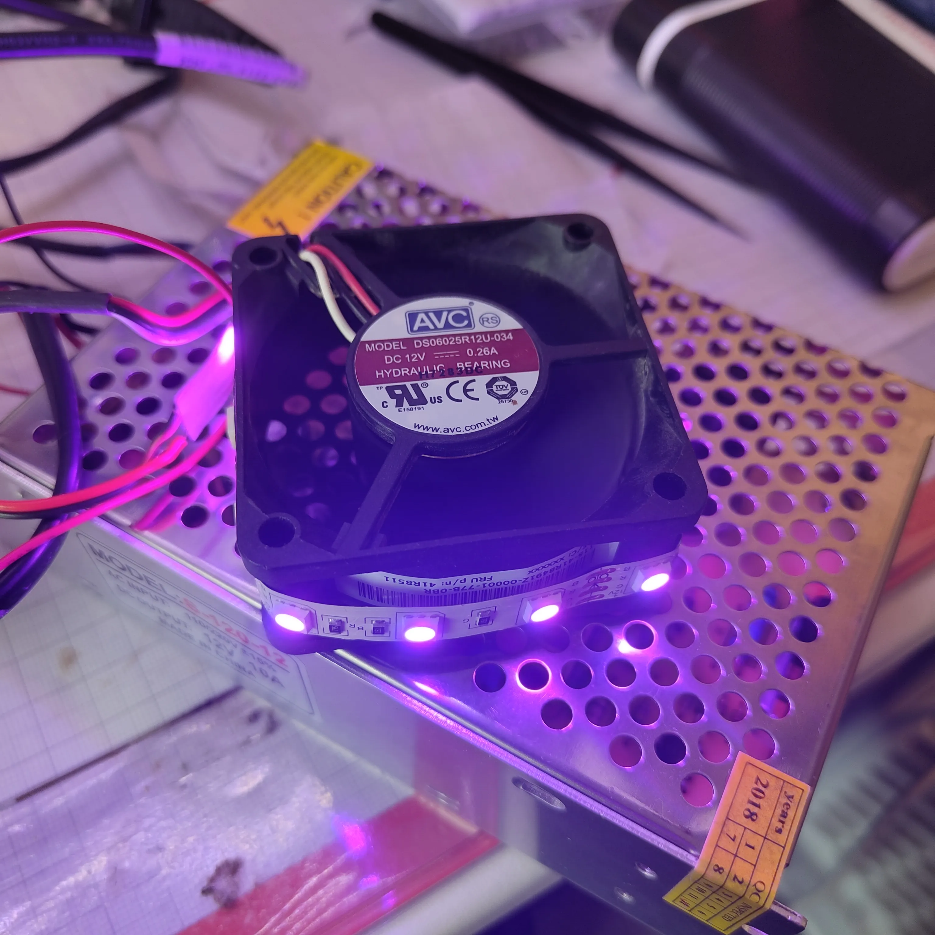
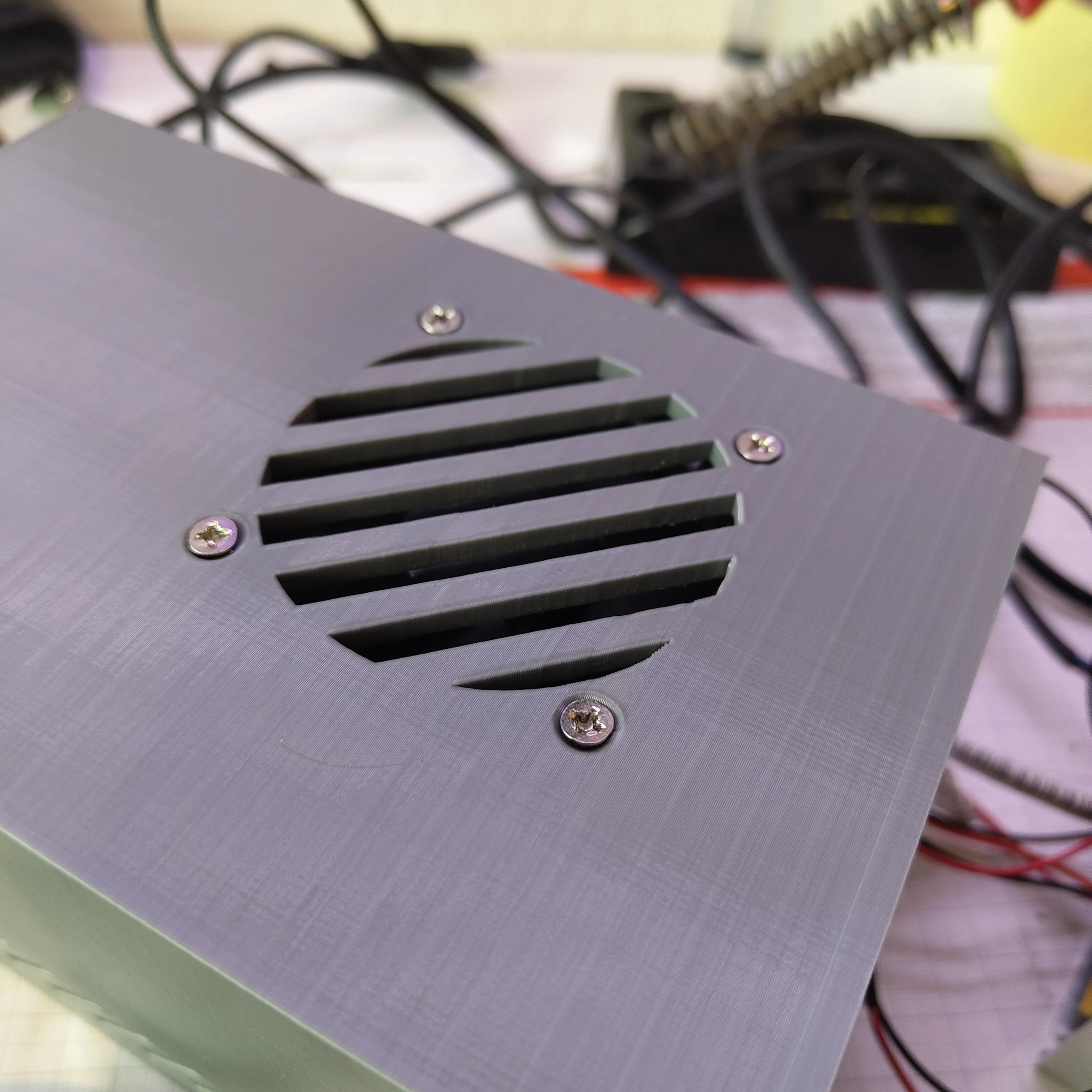
7. Mount the 60 mm fan with M5 screws, airflow drawing in from the top.
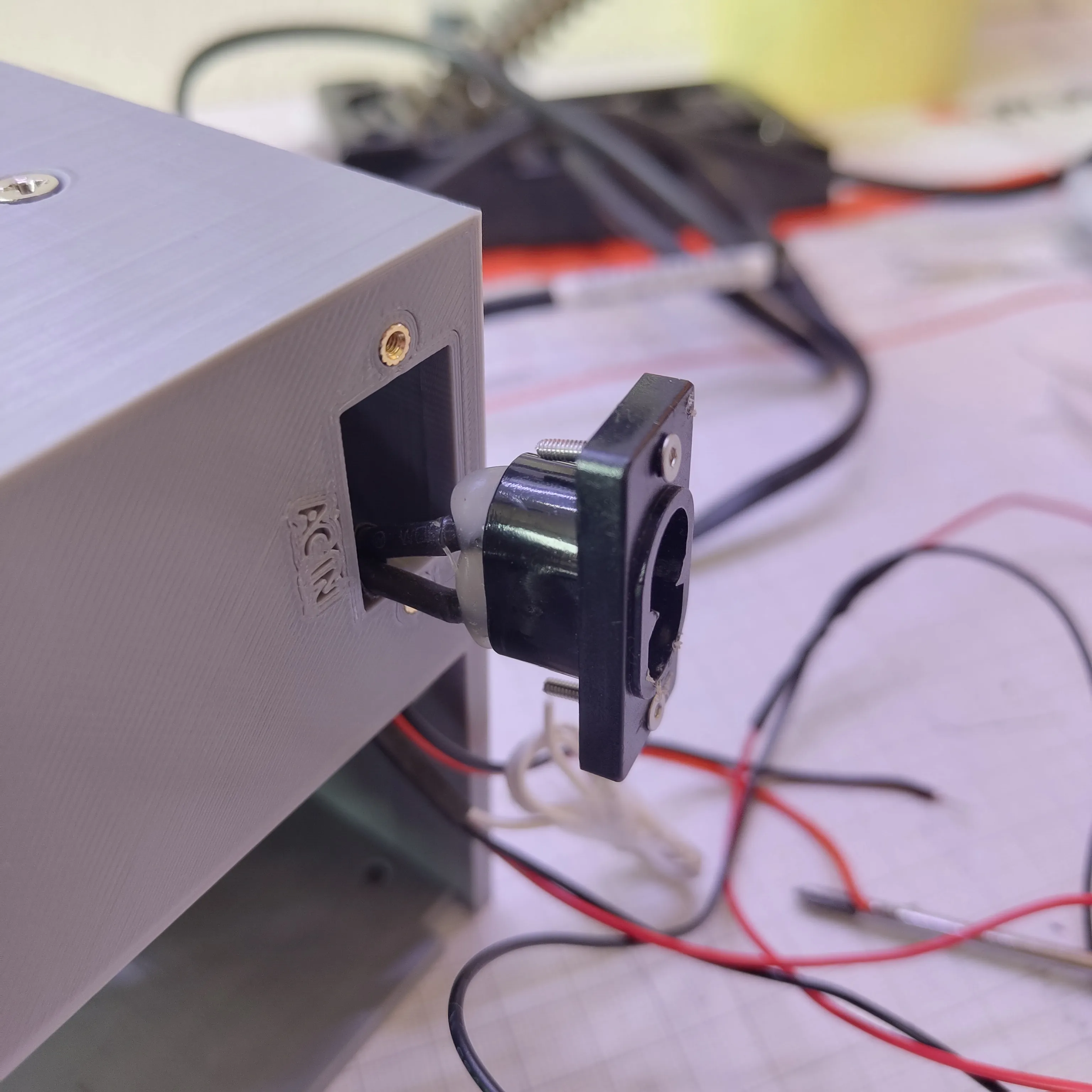
8. Mount the AC inlet (8-shaped socket) with M2 screws.
9. Slide the PSU in 2/3, connect L/N from the inlet, VIN+/VIN- and the fan to V+ / COM, then push it fully onto the locating tab.
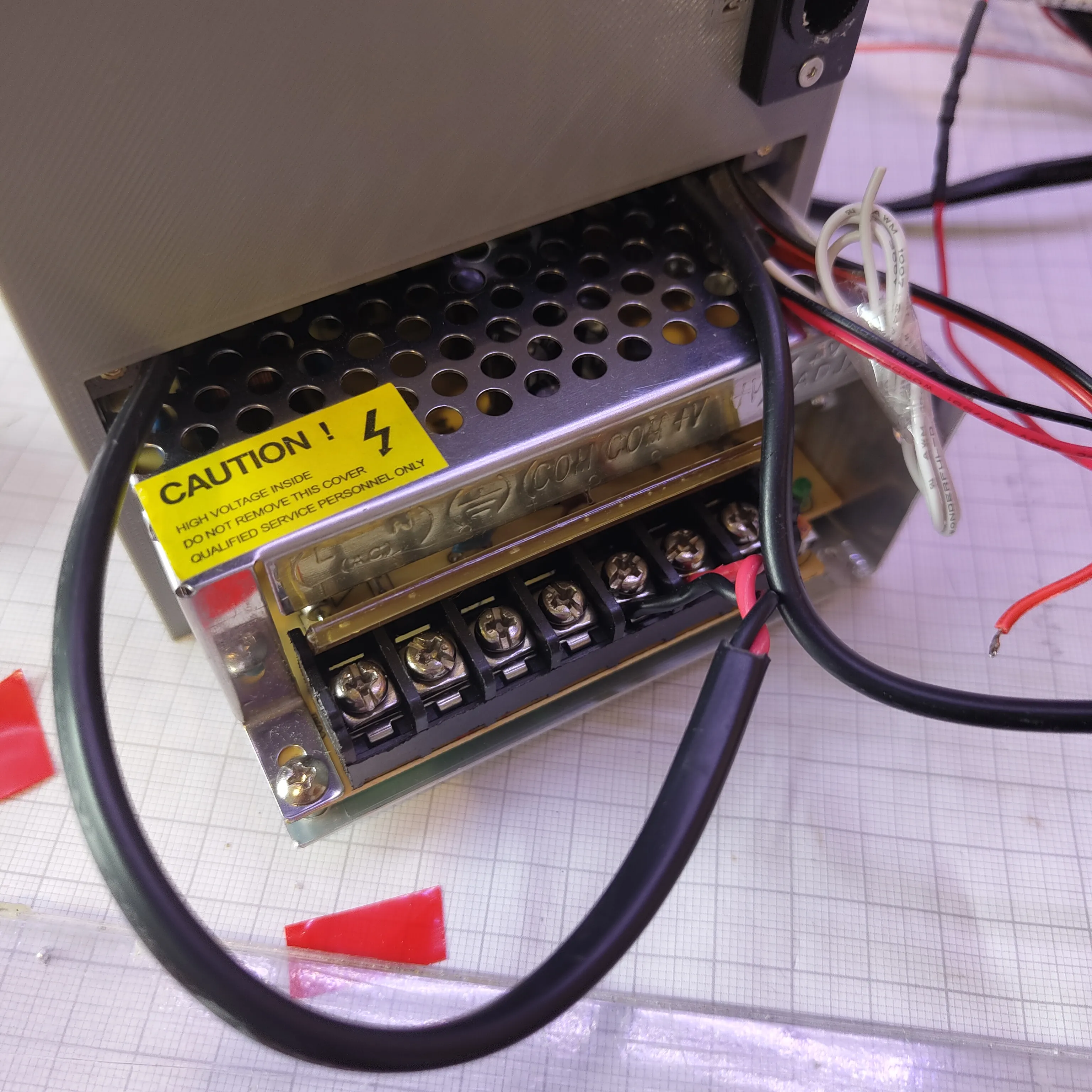
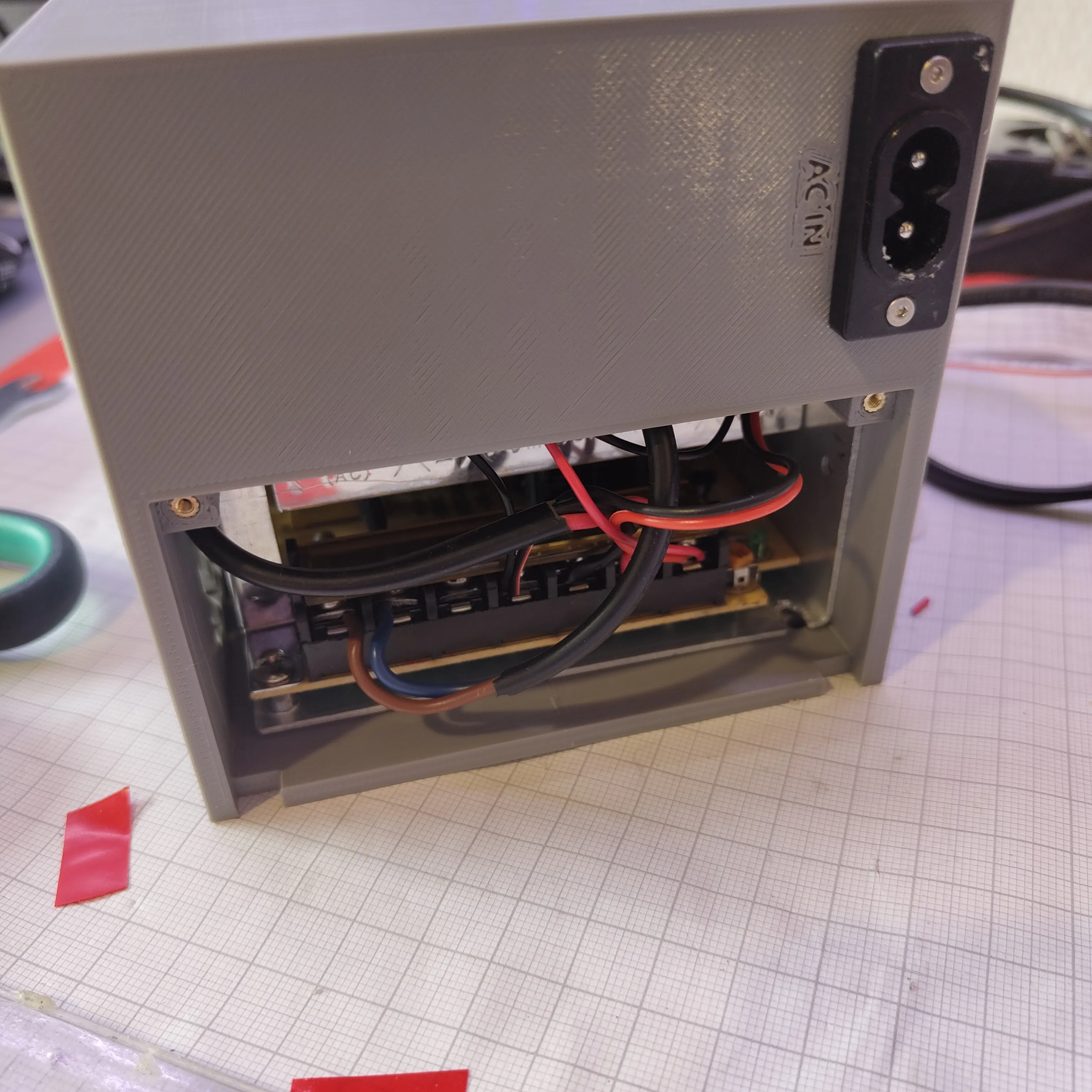
10. Fasten the bracket with M2 screws. Done — test it.
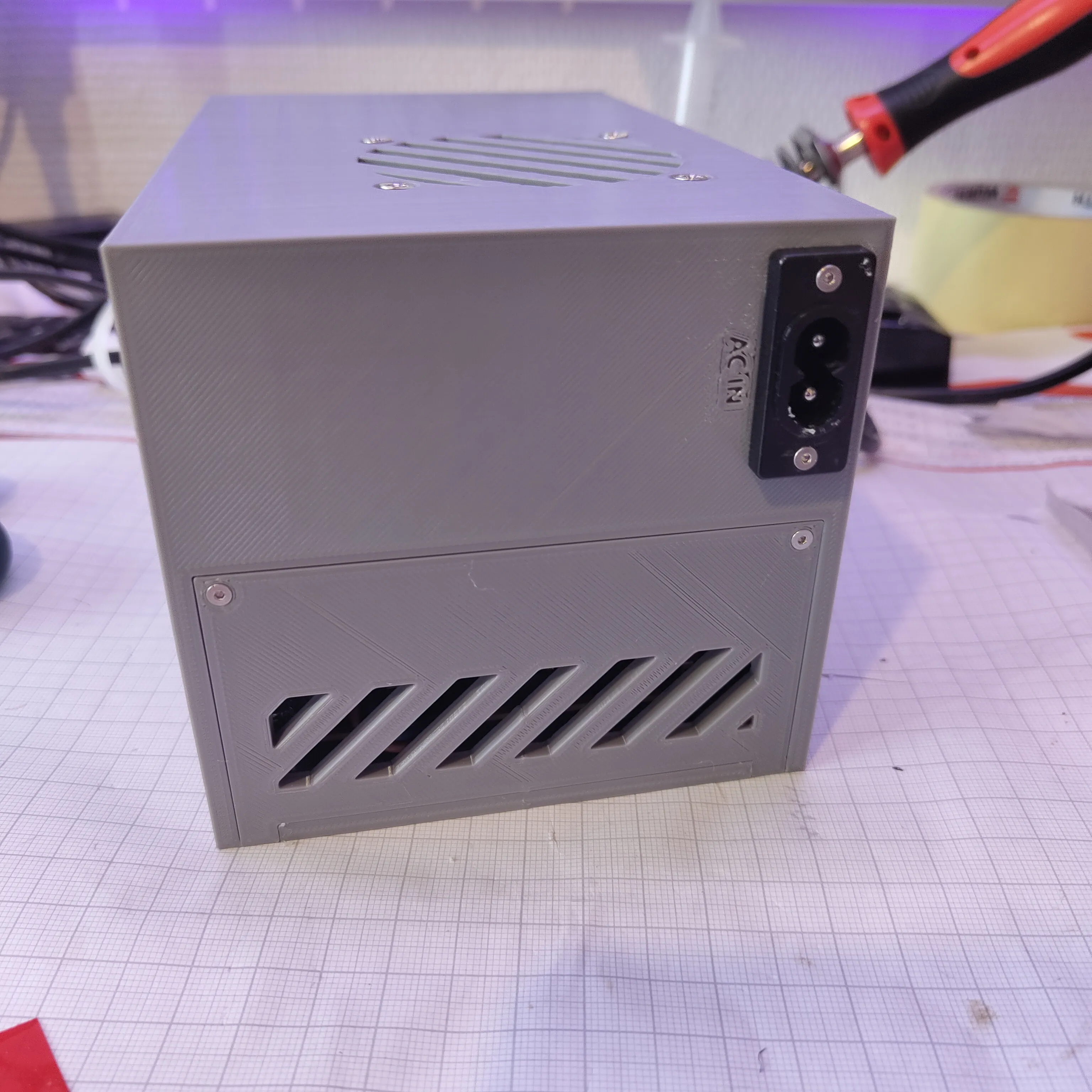
A full illustrated step-by-step build, the wiring diagram, and the complete material list are included here in this profile (parts listed by name and spec).
Material list
- DC-DC buck-boost converter with color display — model SK90C (0.5–36 V, up to 90 W) (Find it on AliExpress)
- Internal PSU: 12 V DC, 10 A, 120 W (220 V AC in, EU plug)
- Banana jacks (female) with mounting hardware
- 60 mm 12 V fan (ball-bearing recommended)
- 18 AWG DC wire
- 8-shaped (C8) AC inlet socket + AC power cable
- M2 flat-head screws (assorted lengths)
- M2 brass heat-set inserts (≈3.5 mm Ø, 3 mm H)
- M5×10 mm fan screws
- Optional: short LED strip; series resistor (~100 Ω) to slow a noisy fan
Safety
This project involves exposed mains AC (220 V). Only operate with the bracket fitted. Unplug before assembling, and never touch the PSU terminals or capacitors during or shortly after use — supplies can hold charge. This is intended as a bench/testing supply, not an unattended or permanent power source. Make sure every part is rated and wired per its own datasheet; you are responsible for safe assembly.
Boost Me (for free)
Support the project by boosting this model! :)
License

You shall not share, sub-license, sell, rent, host, transfer, or distribute in any way the digital or 3D printed versions of this object, nor any other derivative work of this object in its digital or physical format (including - but not limited to - remixes of this object, and hosting on other digital platforms). The objects may not be used without permission in any way whatsoever in which you charge money, or collect fees.


Comment & Rating (2)