
Nintendo 2DS Dual Speaker Mod
Print Profile(0)
Description
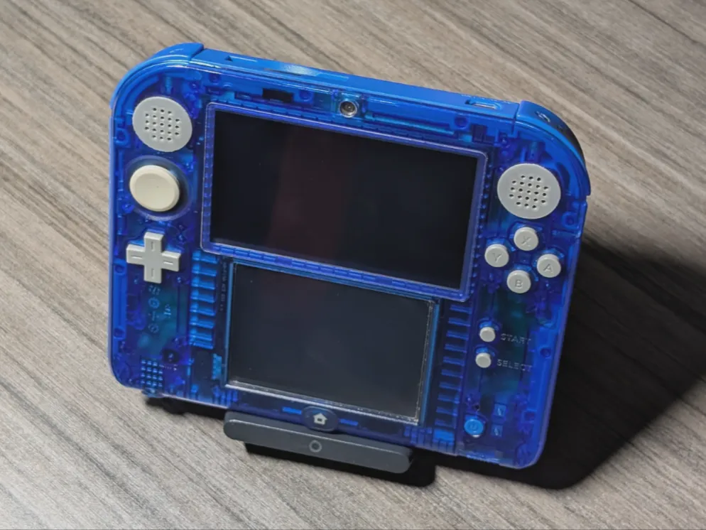
This mod adds a secondary speaker to the 2DS which includes larger speaker grills for a slight increase in max volume. Includes drill hole guide jigs.
Important notes:
- Many permanent modifications will be done to the system shell. Keep a slow pace.
- The secondary speaker will cover the notification LED. I have not achieved an appropriate method of directing light elsewhere.
- The audio setup will remain mono as the secondary speaker will be fed from the existing Sp1 Sp2 terminals. This does not convert to stereo.
Print notes:
- Slicer settings should prioritize precision. I would avoid fuzzy as it may prevent correct fit.
- Printed with 0.4mm nozzle.
- 0.16mm layer height.
- No adhesion brimming used.
- You may need to trim away any unevenness from the PLA settling on the print bed.
Resources used for the mod:
- Imperial (fractional inch) drill bit set.
- Soldering iron with beveled (flat) tip and pointed tip.
- High purity solder and flux.
- 30AWG red and black wiring.
- A dremel kit. I used this kit.
- Box cutter blade for trimming excessive PLA and shaving tight spaces.
- Needle nose pliers.
- Strong double sided tape.
- Kapton tape.
- A secondary 2DS speaker or something equal in size and rating. I used an OEM speaker from a donor 2DS. I have not verified a 3rd party source. Searching 8Ohm round internal magnet mini speaker would give ballpark results on Aliexpress and other sites.
- A secondary 2DS speaker foam o-ring. I used OEM. Not using any sort of cushioning for the speaker may produce rattling at louder volume.
Assembly steps:
(Optional: skip to step 8 if you want to only do the secondary speaker. Adding a new speaker cover for the first speaker is mainly for aesthetics. Although exposing the first speaker more may give a slight jump in volume.)
If printed parts are not fitting right, look for any print faults and spots to trim with the box cutter blade. You will likely need to trim any PLA which has settled on the print bed.
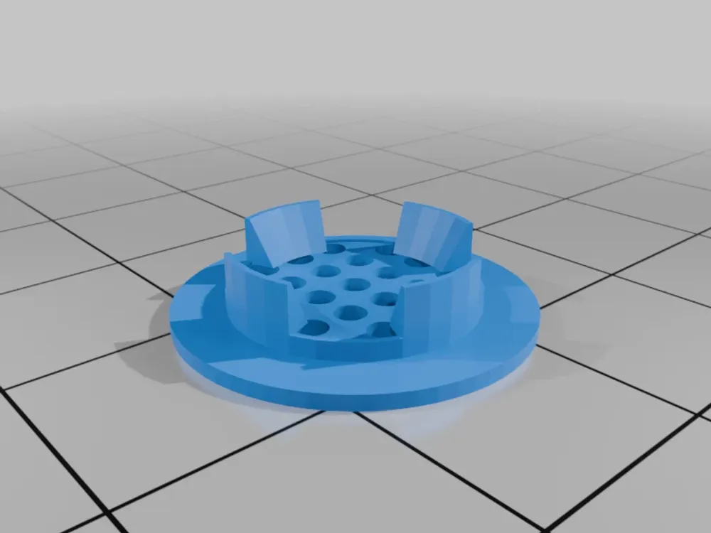
- Print the new speaker cover(s) and the speaker inner fitting(s). Do any appearance sanding here before assembly. The cover should line up and fit inside the grooves of the fitting piece.
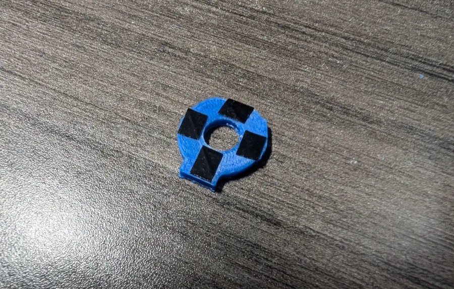
- Print all of the screw guide jigs and make sure the drill bit sizes for 5/32 in, 1/4 in, 3/8 in, 1/2 in fit their respective holes and rotate freely without snagging any PLA.
- All screw guide jigs should fit inside the first existing speaker housing snug but it should not require a lot of pressure to push all the way down. Trim away any excessive PLA material on the outside which is preventing insertion.
- Apply tape to the side of screen you are drilling on. This would help prevent plastic trimmings from getting inside the screen.
Start the hole drilling process by using the 5/32 in jig first then work up to the larger size holes. Line the underside of each jig with double sided tape so it stays in place better while drilling. A perfect hole is not expected but the speaker cover should fit snug and flush against the top shell while staying in place on its own.
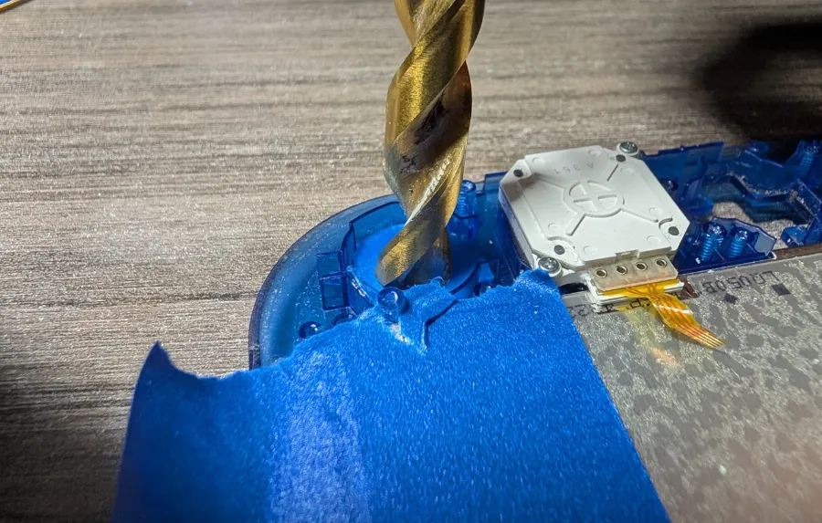
- With the speaker cover in place and aligned straight, place the inner fitting piece which should fit snug in the speaker housing while lining up with the speaker cover tabs.
Take the soldering iron, and while using the beveled (flat) tip at 250C, slowly press down the speaker cover tabs outward welding it to the inner fitting. I would keep downward pressure on the speaker cover and inner fitting piece so it is tight against the shell as it is welded in place. Make sure no jagged piece of PLA remains. Any could puncture the speaker. The tabs should be all welded down flush.
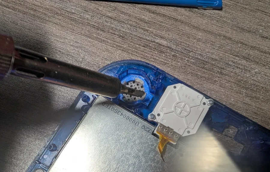
- The new speaker cover is now done and the secondary remains.
Use the dremel and box cutter blade to trim down the notification LED area to fit the new speaker housing. Red lines are recommended cutting paths with either dremel or box cutter blade. Orange lines should trim back cautiously while repeatedly checking the new speaker housing fits without bending too much and remains snug. Use the pliers to gently twist and break off bits one at a time after cutting vertically through the raised plastic with the dremel saw.
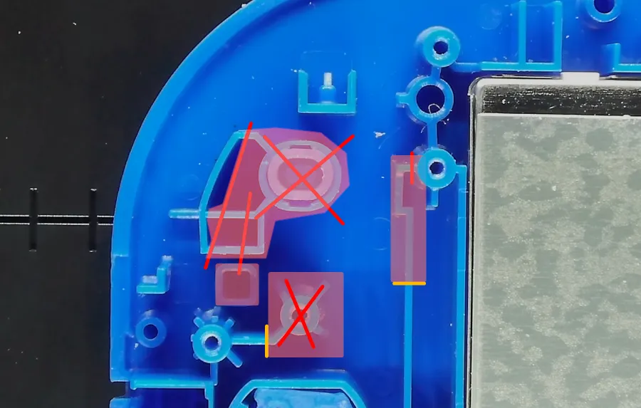
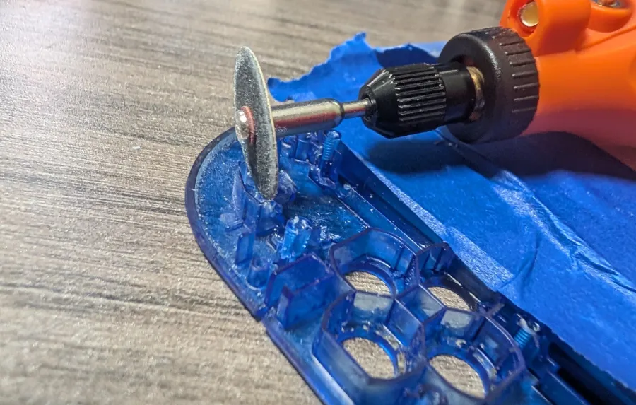
Once the marked areas are pried off, use the dremel's flat tip to sand the remaining raised plastic downward flush to the shell.
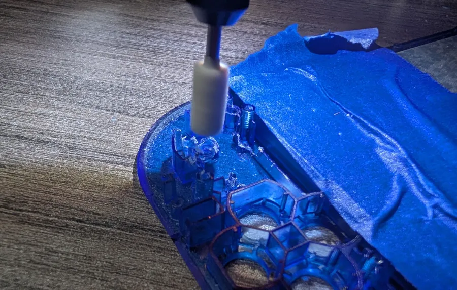
- The new housing should fit flush against the shell and have very little play to it on both lower edges.
- Finally test the new speaker fit inside the housing. It will need to go down at an angle so it slides inside the housing opening.
- Test fit the drill guide jigs inside the new speaker housing. They should have very little play.
Only if the first speaker cover mod was done: Take two 5/32 in guide jigs and place them inside both speaker housings. Verify the horizonal alignment of the holes are relatively straight with each other and not lop-sided.
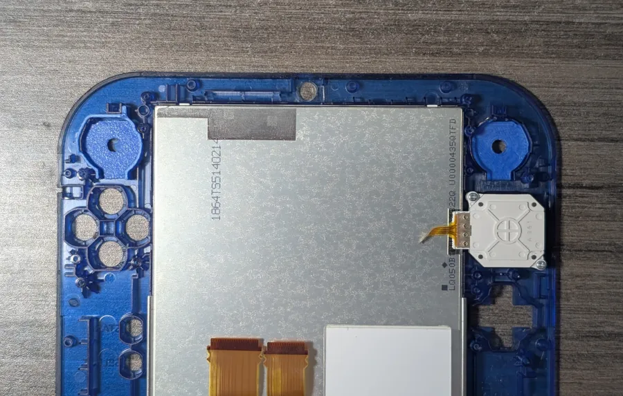
- Refer to steps 4-7 for installing the new speaker cover.
- Test and verify the new speaker fits appropriate inside the new housing with the new speaker cover now affixed to the shell.
- With the black and red 30AWG wiring, cut both wires measuring around 8 inches in length.
- With the 30AWG wiring, solder the two wires to the new speaker. Red being on the left terminal, black on the right (exactly how the original speaker is soldered).
- Apply a small piece of kapton tape covering the metal part of the new speaker to prevent shorting any components.
- Guide both wires through the screw hole in the motherboard and route them between the power pins and game card shell. The speaker on the underside of the motherboard should ideally dangle half inch from the motherboard. Cut away any excess wires once they reach Sp1 and Sp2 terminals.
Twist the wires a few times and tape down the wires then solder both wires to Sp1 and Sp2 terminals matching the color coding of the original speaker.
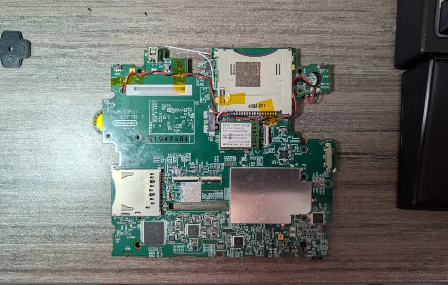
- Place the o-ring into the new speaker housing.
- When reassembling the 2DS, insert the new speaker into its housing first as you put the motherboard in place. With both speakers in, barely lift the left edge to feed the two display ribbon cables through using a pair of needle pliers or the 2DS stylus. Follow the rest of the ribbon cables by barely lifting the motherboard enough to surface them.
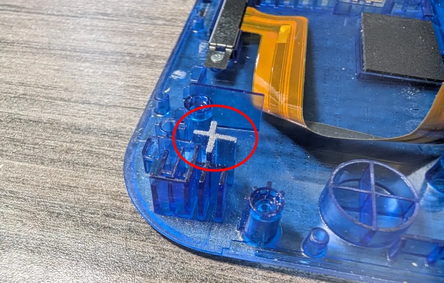
With the motherboard back in place, the R trigger will need some of its plastic trimmed with a dremel for proper fit.
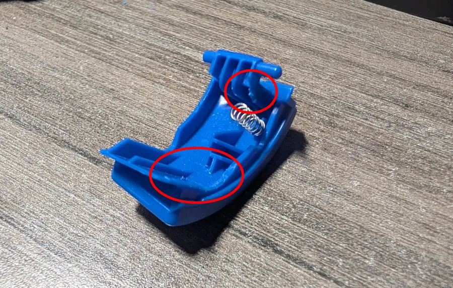
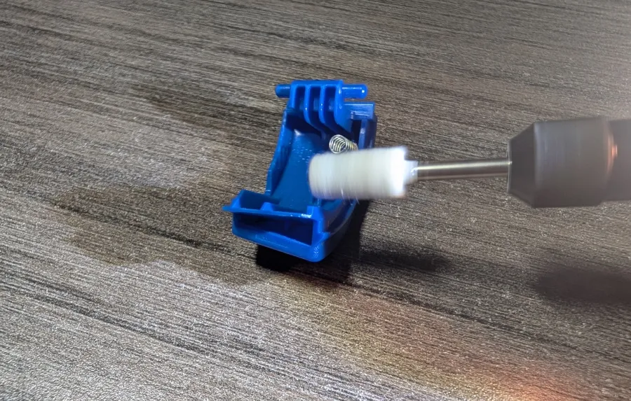
Because of the wiring path, part of the back shell will need minor trimming with a dremel and box cutter blade as shown.
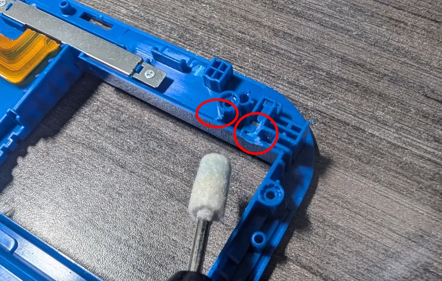
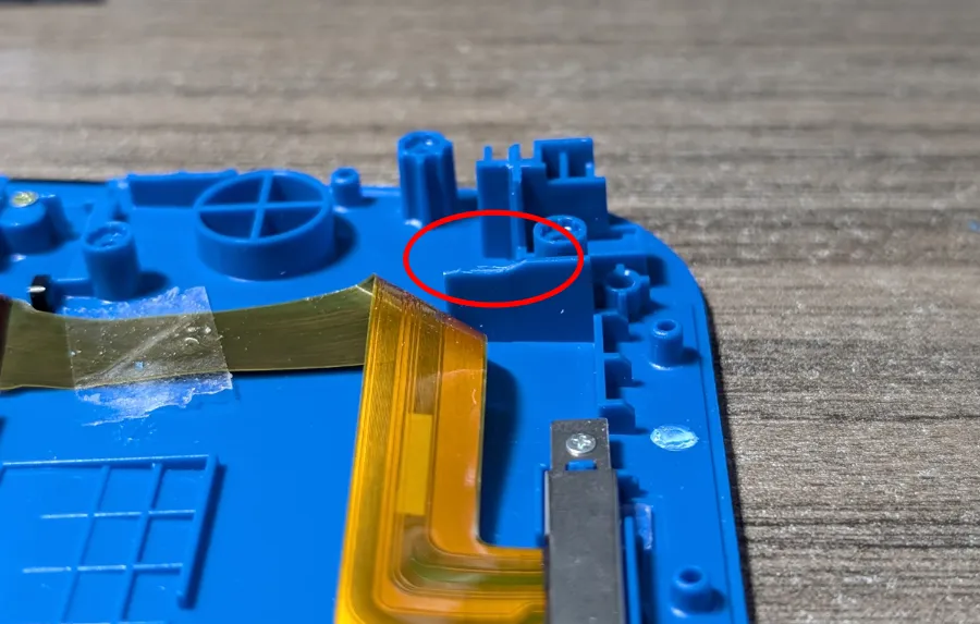
If the original speaker was modified, part of the raised plastic will need to be trimmed back a few millimeters.
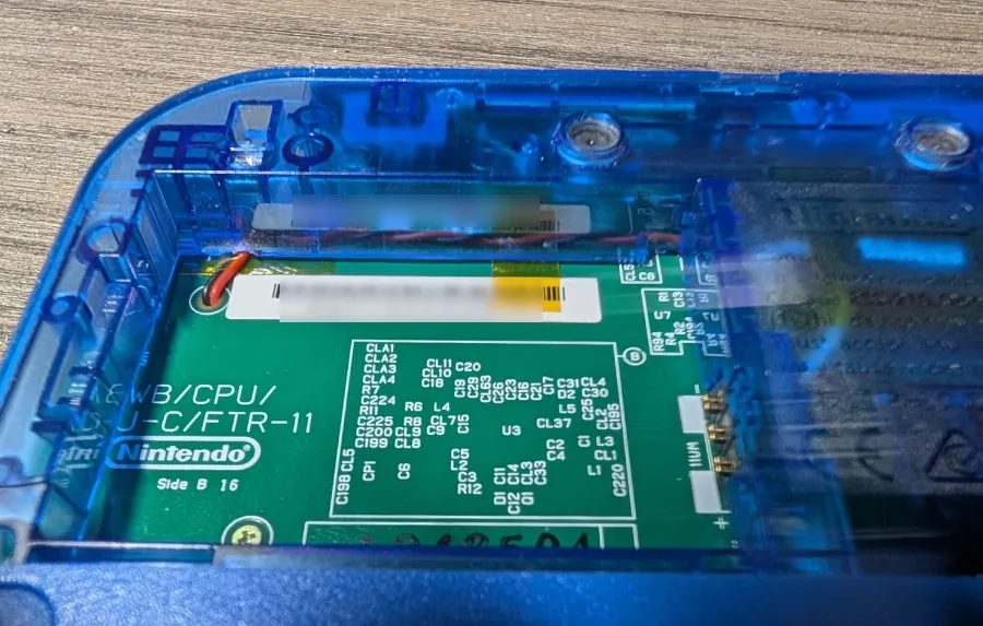
To finish, reassemble the rest of the 2DS. Double check that no speaker wires get snagged when putting the back shell on.
License



Comment & Rating (0)