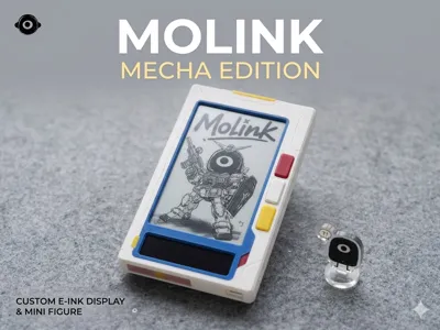
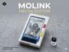
MOLINK Dual-Screen Reader Personalized Series — Mecha Edition


Print Profile(2)
Description
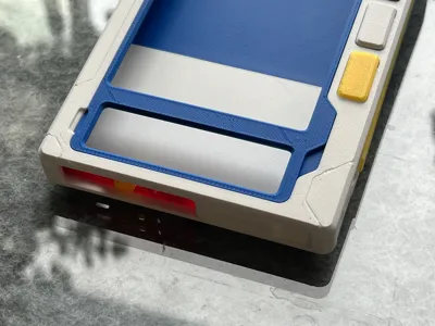
Molink Reader Mecha-style Shell
This series of 3D printed shells is specifically designed for the Molink dual-screen reader developed by Xia Xiang Jushi
(Note: Only supports the internal test and standard version motherboard with a 4000 mAh battery)
Appearance Design:
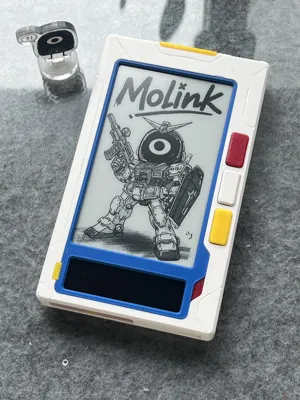
The overall design adopts a mecha theme, with tech-inspired decorative details and etched lines added to the surface
Parts and Printing:
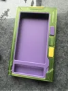
The model has undergone detailed partitioning
Using a regular monochrome printer, you can print parts of different colors separately to achieve a colorful effect after assembly
However, it is still recommended to use dual-extruder or AMS-equipped models for better color separation
Color Scheme Suggestions:
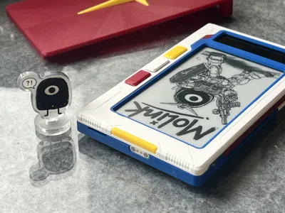
The default configuration in the file is the "Gundam RX-78" color scheme, and it includes a matching themed external reading light integrated protective cover
You can also refer to the renderings, achieve better results by changing filaments of different colors, adding decals, spray painting, and other treatments, combine different themes yourself, or match colors entirely according to personal preference

Installation Instructions:

I. Main Body (Basic Shell)
1. Hardware and Metal Accessories
- Screws: M1.6*5 flat head self-tapping screws (several)
2. Printing Instructions
- The model has been physically partitioned, allowing direct printing of different colored parts using a regular monochrome printer, without the need for a multi-extruder printer or AMS. The default configuration is the "Gundam RX-78" color scheme, which can be adjusted by changing filaments
3. Assembly Steps
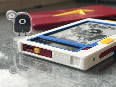
- Shell assembly: Assemble the printed and separated shell parts of various colors with snaps and fix them with glue
- Main body fixing: Assemble the core inner frame as with the previous standard version, then use M1.6*5 flat head self-tapping screws to tighten and fix the shell to the core inner frame
- Install magnetic interface: If you plan to use the flip-cover reading light integrated protective cover, you will need to solder the magnetic interface wires to the original light strip pads on the motherboard
II. Flip-cover Reading Light Integrated Protective Cover (Optional)
1. Hardware and Metal Accessories
- Hinge screw: M1.6*8 flat head self-tapping screws (used as a flip-cover hinge)
- Fixing screws: M1.6*5 flat head self-tapping screws (several)
- Power interface: 2P lug-type Pogopin magnetic connector (1 pair)
- Light source module: 3.7V powered 8mm wide cuttable high-density LED soft light strip (or 35*8mm rigid light strip)
2. Printing Instructions
- Core inner frame: You must print the mecha version core inner frame (this version adds support structure for the Pogopin magnetic interface)
- Light cover model: Print the reading light integrated protective cover model
3. Assembly and Wiring Steps
- Interface installation: Install the male and female connectors of the 2P Pogopin magnetic connector respectively into the reserved holes in the dedicated core inner frame and protective cover (pay attention to the magnetic attraction direction and polarity)
- Light strip fixing and wiring: Cut an appropriate length of LED soft light strip (approximately 35mm), fix it to the inside of the protective cover, and solder/connect the light strip wires to the Pogopin connector on the protective cover, ensuring the 3.7V power supply circuit is conductive
- Hinge assembly: Align the protective cover with the hinge hole of the inner frame, screw in an M1.6*8 flat head self-tapping screw as a flip-cover hinge. Fine-tune the tightness of the screw to ensure the protective cover folds smoothly and the magnetic interface can precisely engage for power supply
Note: No circuit-related tutorials are provided, please do not ask. DIY carries risks. If you do not know how to install it, please entrust it to others or acquire sufficient knowledge before proceeding, as blindly following instructions can easily lead to problems
License
You shall not share, sub-license, sell, rent, host, transfer, or distribute in any way the digital or 3D printed versions of this object, nor any other derivative work of this object in its digital or physical format (including - but not limited to - remixes of this object, and hosting on other digital platforms). The objects may not be used without permission in any way whatsoever in which you charge money, or collect fees.
Comment & Rating (0)