Stepper-Driven Syringe Actuator & Z-Axis


Print Profile(1)
Bill of Materials

- M3 Standoff x 8:
- M4 Socket Head Cap Screw x 8:
- Linear bearings 8mm IDx 24mm Length x 4:
- M3 Socket Head Cap Screw x 10:
- M3 Heat Set Insert x 2:
- M4 Button Head Nut x 24:
- M4x4 Heat Set Insert x 20:
- Nema 17 Stepper Motor x 2:
- Pillow Bearing x 3:
- Flexible Shaft Coupler x 2:
- T8 brass nut x 2:
- T8 150mm Lead Screw x 2:
- Stainless Steel Round Rod 8mm x 150mm x 6:
- Aluminum Extrusion 20x60mm x 2:
Description
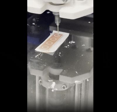
This is a Stepper-Driven Syringe Actuator & Z-Axis — a precision dispensing mechanism driven entirely by stepper motors. I originally developed it as a precision dispensing platform, and while it handles a wide range of materials, the underlying mechanism is flexible enough to adapt to all sorts of applications — from electronics assembly to adhesives, sealants, and fine fluid deposition.
Boost Me (for free)
Built this as a precision dispensing platform and wanted to share it freely. If it's useful to you, a boost is always appreciated — thank you!
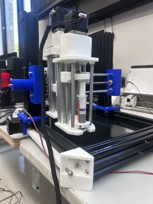
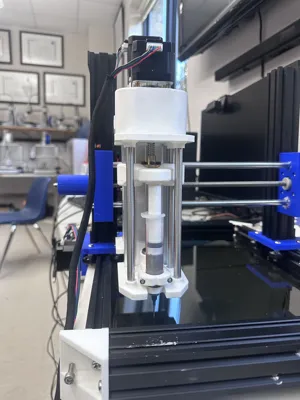
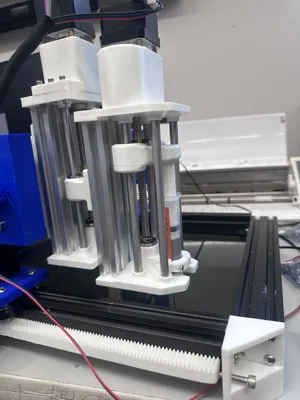
The system is built around two NEMA 17 stepper motors. One drives the syringe plunger to control material extrusion, and the other handles Z-axis travel. NEMA 17s were a deliberate choice here: they offer plenty of holding torque for the plunger drive, integrate cleanly with common driver electronics, and give precise, repeatable positioning without the cost or complexity of closed-loop systems.
A neat feature of this design is that it's not limited to dispensing — because the plunger is fully under motor control in both directions, you can run the syringe in reverse to create suction instead. That opens up a whole second set of applications, like a vacuum pick-and-place tool for handling small parts, components, or anything light enough to lift with a bit of negative pressure.
In testing, the mechanism performs very well, though I'll be upfront that assembly takes some patience. I printed all my parts in PLA, but I tuned the print settings specifically for mechanical strength: thicker walls (around 4 perimeters) and gyroid infill for a good strength-to-weight ratio in every direction. PLA was fine for prototyping and proof of concept, but for any long-term or heavy-duty use I'd strongly recommend PETG, ABS, or ASA, which hold up far better to sustained mechanical load and heat.
One refinement I made after taking the photos was a full redesign of the plunger motor mount. The original worked, but the updated version mounts the same way as the Z-axis assembly — which keeps the design consistent, improves rigidity, and makes the whole thing noticeably easier to assemble.
To build this model, you'll need a tap to thread the holes in the aluminum extrusion mounting plates, along with the heat-set inserts called out in the BOM. Every required component is listed there.
On the electronics and code: I haven't gone too deep on the software side yet, but I did have it fully working. I'd recommend a servo driver board paired with an Arduino (or a similar microcontroller) — that's the setup I used, and it gives you direct, fine-grained control over the dispensing motion.
The more interesting challenge is tuning the control logic to the viscosity of whatever material you're dispensing. This is where a dispensing mechanism like this really earns its keep. Solder paste, for example, behaves non-Newtonically and tends to stiffen as it sits, so it needs a high initial force to break it loose and start moving, after which it flows much more easily — meaning your code ideally accounts for that startup spike rather than driving at a constant rate. At the other end of the spectrum, a thin fluid like water needs barely any force at all, so the motor effort can be dialed way back. Through testing, I found the practical sweet spot for a mechanism like this is roughly the viscosity of cake icing or honey. I wouldn't push much past solder paste — the motor started to struggle once the paste had begun to dry and thicken, which is a good real-world limit to keep in mind when matching the machine to your material.
I'm currently developing improved X- and Y-axis systems. The versions shown in the photos use a rack-and-pinion design on a gantry, which works but has limitations: because so many of the components are 3D printed, the system isn't as accurate as I'd like, and it relies on two stepper motors. The Y-axis in particular is a little underbuilt for the weight of the full assembly, so that's a primary focus of the next revision.
Looking further ahead, a really compelling upgrade would be replacing the plunger's stepper motor with a pneumatic cylinder and compressor. That would give smoother, more consistent pressure-based dispensing and sidestep the startup-force problem entirely — I simply ran out of time and resources to implement it on this build.
If there's interest, I'm happy to share the improved X- and Y-axis modules as I finish them. Let me know what you'd like to see next, and what other 3-axis machine projects you'd be interested in!
License
You shall not share, sub-license, sell, rent, host, transfer, or distribute in any way the digital or 3D printed versions of this object, nor any other derivative work of this object in its digital or physical format (including - but not limited to - remixes of this object, and hosting on other digital platforms). The objects may not be used without permission in any way whatsoever in which you charge money, or collect fees.
Comment & Rating (4)