
Wind Turbine Project | Functional Simple Turbine
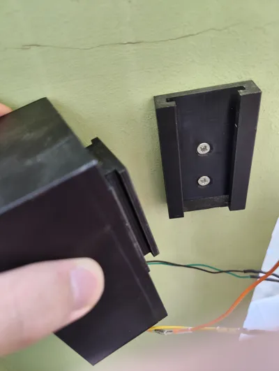
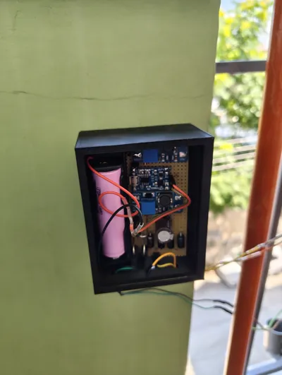
Print Profile(2)


Description
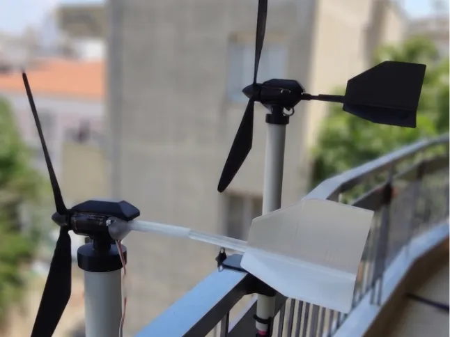
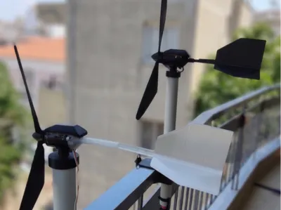
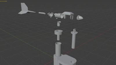
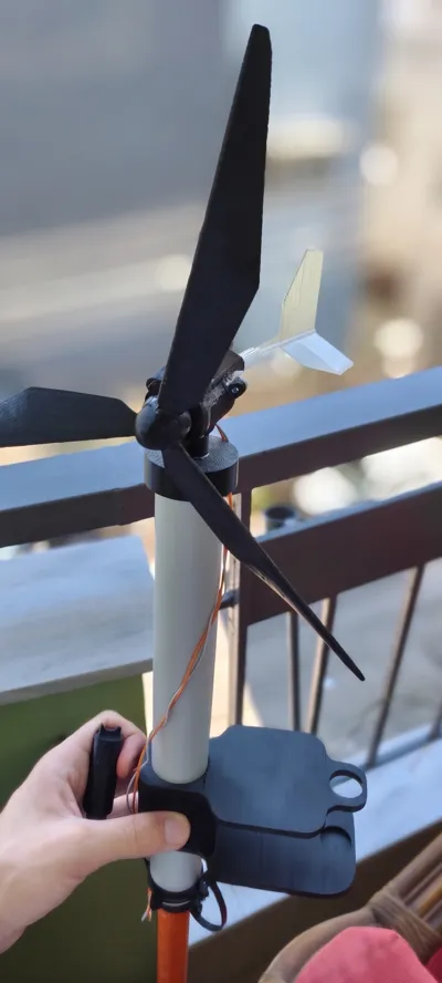
This is a heavily modified and fully functional remix of the excellent "Basic Wind Turbine" by kjt270000. This remix transforms the original core concept into a practical, power-generating system designed specifically for apartment balconies and off-grid experimentation.
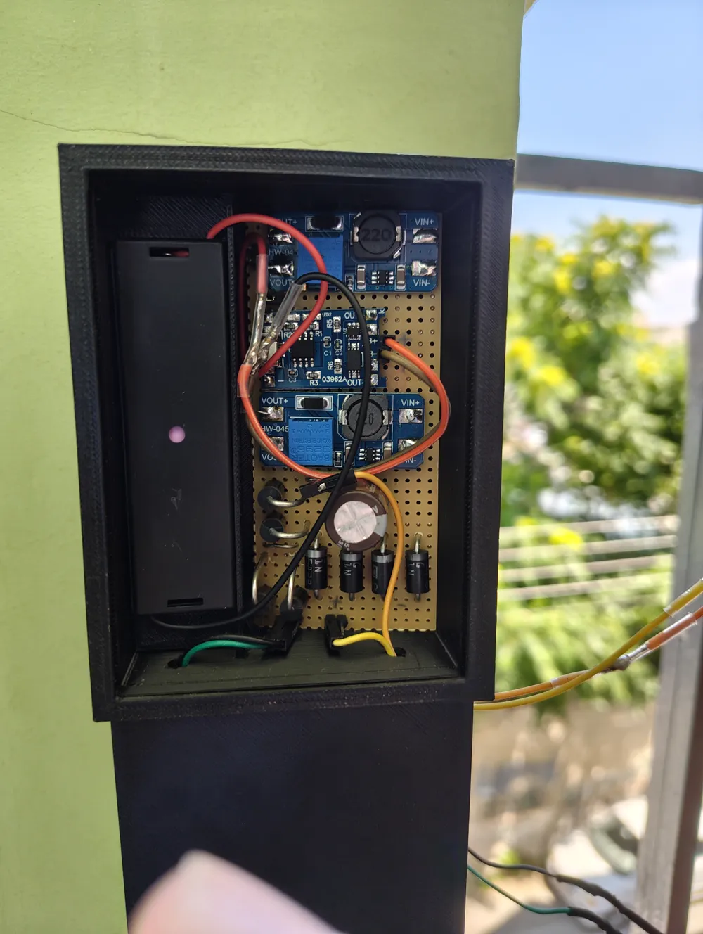
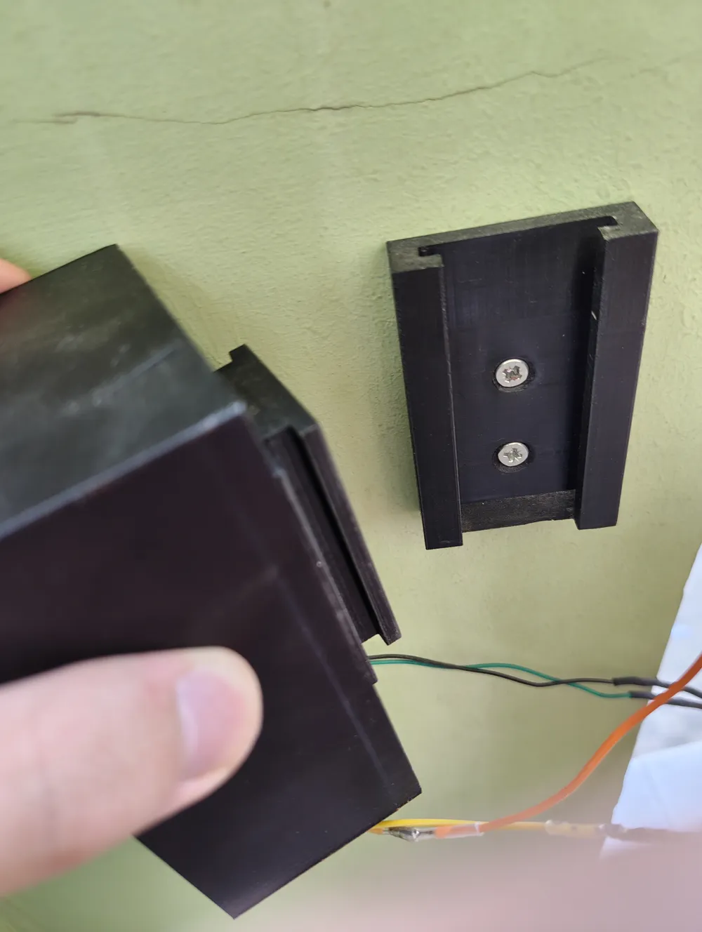
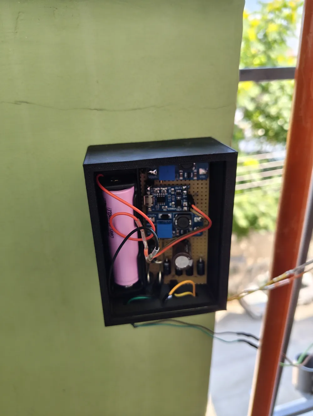
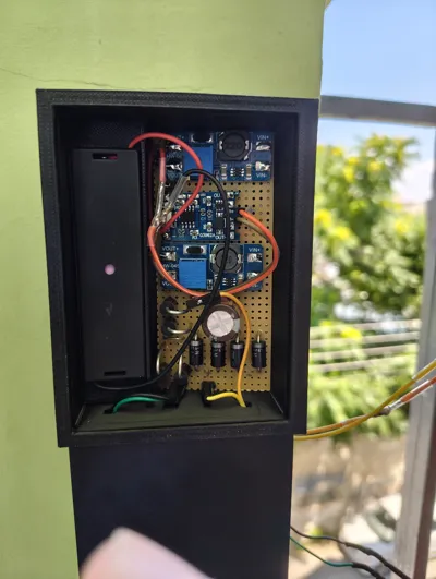
This project includes completely redesigned mounting hardware, weatherproofing additions, structural reinforcements, and a complete perfboard electronics enclosure to harness the wind and charge an 18650 lithium-ion battery.

🛠️ What's New in this Remix?
Two Optimized Sizes
- Medium Version: Retains the 24mm motor from the original model. Ideal for standard winds and smaller spaces.
- Large Version: Upgraded to house a 32mm motor, significantly increasing power generation potential for easier battery charging.
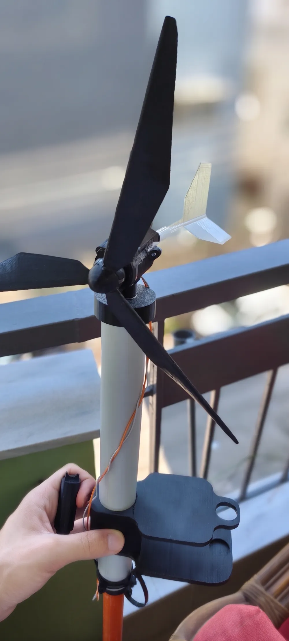
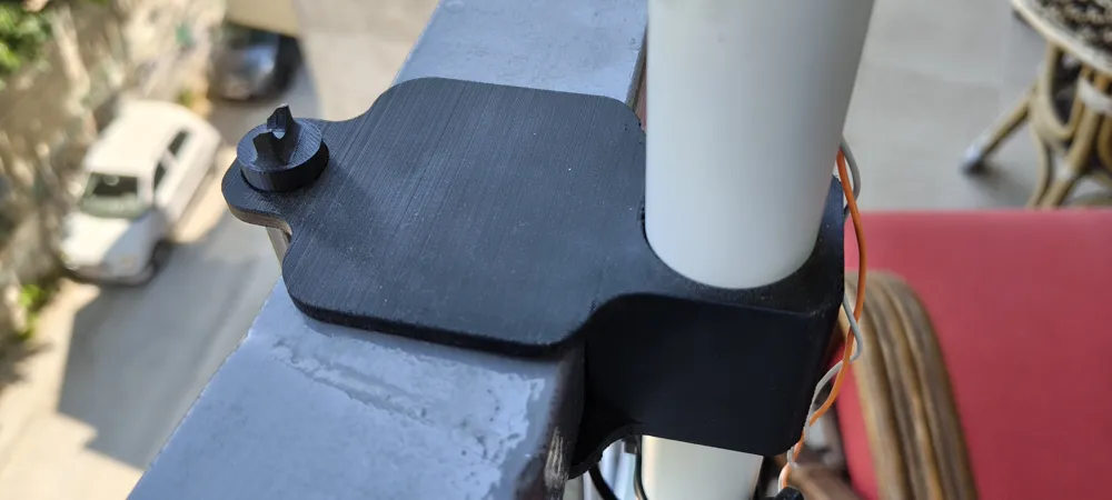
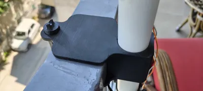
Balcony-Ready Mounting System The mounting system has been completely engineered from scratch to easily clamp onto a typical balcony barrier.
- The Mast: Designed to use a standard 32mm (external diameter) PVC pipe with a 2.5mm wall thickness as the main tower.

- Free Rotation Yaw: To ensure the turbine can freely track wind direction (yaw) without friction, the design incorporates a standard bearing (27mm External Diameter / 15.5mm Internal Diameter) at the pivot point.
Structural & Weatherproofing Upgrades
- Motor Cover: Added a top cover for the motor housing to improve weather resistance. (Note: While it provides splash and light rain protection, leaving the turbine out in heavy, continuous rain is still not encouraged).
- Tail Support: A new stabilizing brace was added to the tail section. This prevents the tail from sagging or bending under its own weight over time due to the natural layer orientation of FDM printing.
Smart Cable Management
- On both versions, the main pivot body features a specific internal routing path. The cables run straight from the motor, inside the PVC pipe, and out the bottom. This prevents the wires from wrapping around the mast as the turbine rotates.
⚡ Electronics Overview (No Custom PCB Required!)
Hardware Components List
Core Modules & Power
- 1x 18650 Lithium-Ion Battery (3.7V, unprotected cell is fine since the circuit has protection)
- 1x 18650 Single Cell Battery Holder
- 1x TP4056 Lithium Battery Charging Module (Ensure you get the version with the built-in protection circuit—it has OUT+ and OUT- pads in addition to B+ and B-).
- 2x MT3608 DC-DC Step-Up Boost Converter Modules (Often marked as HW-045).
Basic Electronic Components
- 4x Rectifier Diodes (1N4007 are standard, but 1N5819 Schottky diodes are highly recommended here for better efficiency and lower voltage drop).
- 1x Electrolytic Capacitor (Values around 470µF to 1000µF, rated for at least 16V or 25V).
- 1x Perfboard / Prototype PCB (Standard dot-matrix board, cut to fit your 3D printed enclosure).
Miscellaneous
- Hookup wire (22-24 AWG stranded wire is ideal for flexibility)
- Solder
How It Works (The Circuit Logic)
- Input & Rectification: The wind turbine motor generates erratic, fluctuating voltage (and possibly AC depending on the motor). The four diodes act as a Bridge Rectifier, ensuring the electricity flows in the right direction regardless of which way the wind spins the turbine. The Capacitor smooths out this rippling voltage.
- Boosting to Charge: The turbine might not always generate the 5V needed to charge the battery. The first MT3608 boost converter takes the smoothed voltage and steps it up to a steady 5V.
- Battery Management: The 5V feeds into the TP4056 module, which safely charges the 18650 battery and protects it from over-charging and over-discharging.
- Output Power: The 18650 battery outputs around 3.7V. The second MT3608 boost converter takes this battery voltage and steps it up to a stable 5V (or 12V, depending on what you are trying to power with the turbine).
Step-by-Step Assembly Guide
Important Pre-step: Before soldering the MT3608 modules into the final circuit, connect a temporary power source to their inputs, hook a multimeter to their outputs, and turn the little brass screw on the blue potentiometer until they output exactly your desired voltages (e.g., 5V for the first one).
Step 1: The Rectifier Circuit (Power Input)
- Solder the 4 diodes onto the perfboard in a bridge rectifier configuration.
- Connect the two wires coming from your wind turbine motor to the AC input sides of the diode bridge.
- Solder the electrolytic capacitor across the positive and negative outputs of the diode bridge. Note: Capacitors have polarity; ensure the negative stripe side connects to the negative trace.
Step 2: Voltage Stabilization (First Boost Converter)
- Connect the Positive output of the capacitor to the VIN+ on the first MT3608 module.
- Connect the Negative output of the capacitor to the VIN- on the first MT3608 module.
- Tune this module to output exactly 5V.
Step 3: The Charging Circuit
- Connect the VOUT+ of the first MT3608 to the IN+ (or standard positive input pad) of the TP4056 module.
- Connect the VOUT- of the first MT3608 to the IN- of the TP4056 module.
- Solder the positive (red) wire from the 18650 battery holder to the B+ pad on the TP4056.
- Solder the negative (black) wire from the battery holder to the B- pad on the TP4056.
Step 4: Output Power (Second Boost Converter)
- Connect the OUT+ pad from the TP4056 to the VIN+ pad of the second MT3608 module.
- Connect the OUT- pad from the TP4056 to the VIN- pad of the second MT3608 module.
- Adjust the potentiometer on this second MT3608 to your final desired output voltage (e.g., 5V for charging a phone, 12V for LED strips).
- Solder your final output wires to the VOUT+ and VOUT- pads of the second MT3608.
Enjoy building, and may the wind be in your favor!





Comment & Rating (0)