
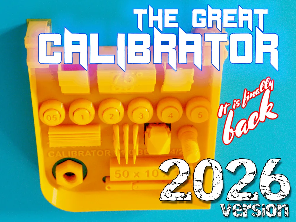
The Great Calibrator - 2026
Print Profile(2)
Description
Here we are again, 3D printing enthusiasts!
It's mid-2026 and, after more than a year, I'm back with a new version of the "Great Calibrator," thanks to the success of previous versions.
The model has undergone a redesign, losing some of the components that had been added to the main model over time and acquiring new ones (few, but effective).
But the most impressive aspect is its compactness, precision, and ease of reading the tests, all while, of course, providing a good amount of stress to both your printer's steppers and nozzles, as well as the filament you're testing.
Use is as simple and intuitive as ever: once printing is complete, let the print bed cool completely, then fold it and remove the main base.
If your printer (or filament, or both) are already well calibrated, you'll notice that many parts will remain attached to the bed or will move away from it without remaining connected to the main base.
This should (definitely) happen for the hinge and the bolt, as well as (probably) for the pins with the widest tolerance.
Pins 3 and below may require a little pressure on the top.
Caution: Don't use excessive force or tools to force a pin out. The goal is to read the tolerance allowed by the printer/filament combination under the conditions you printed under.
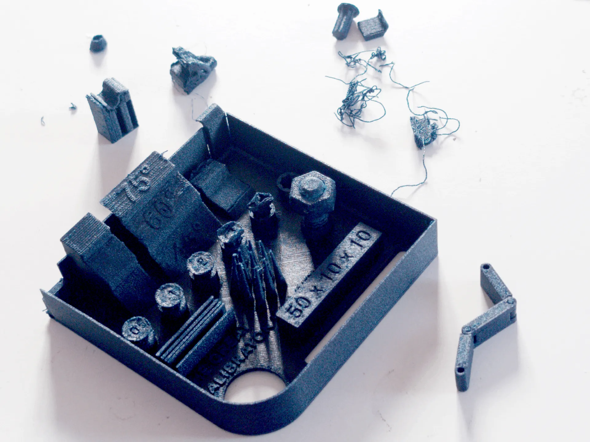 | 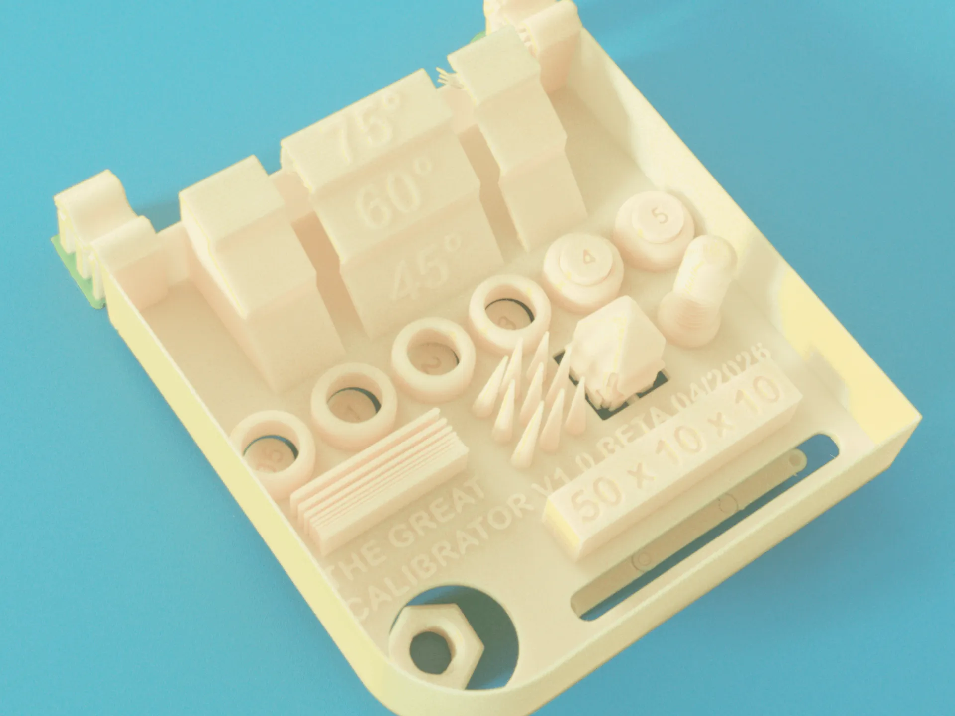 |
An extreme unsuccessful print | A successful print |
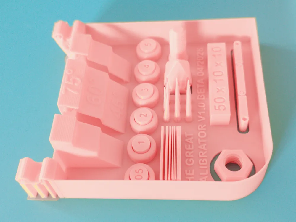
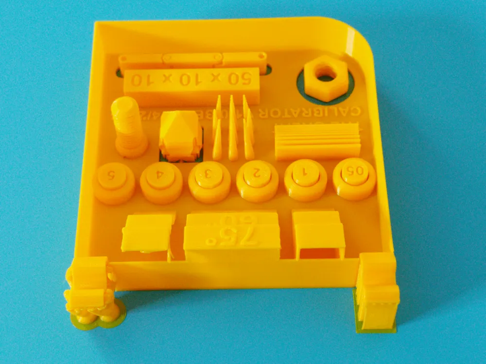
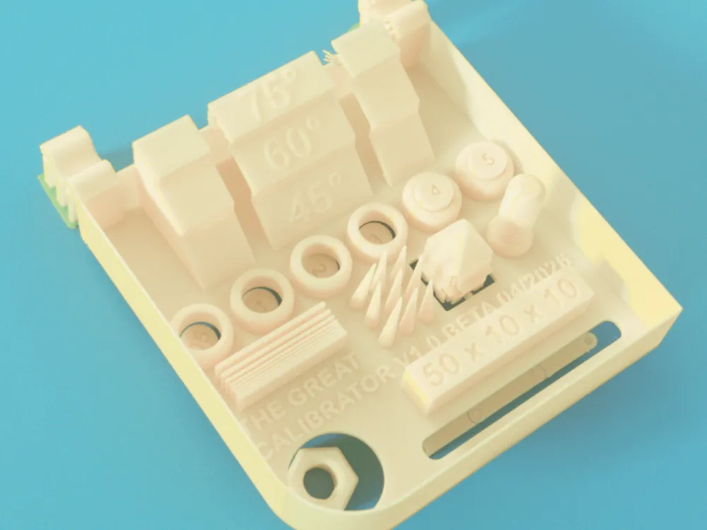
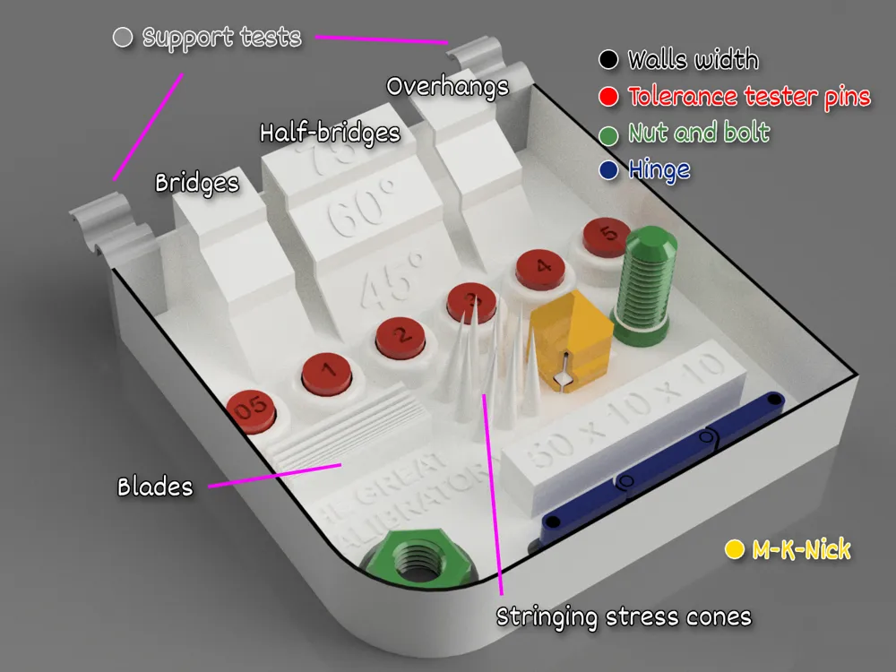
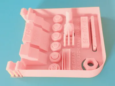
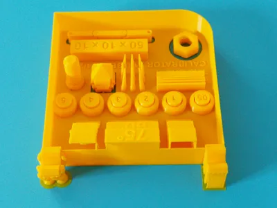
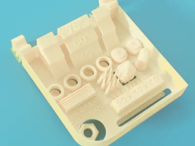
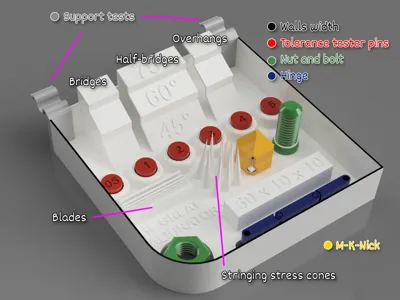
Let's review the model's components.
Walls:
The walls surrounding the main base should measure 0.8 mm, consisting of two 0.4 mm walls (the width of the standard nozzle).
Turrets:
As in previous versions, there are two turrets with a suspended sinusoidal upper part for support testing. You can therefore easily distinguish which method you prefer based on the results obtained.
NOTE: There are two versions: the standard single-material version and the dual-material version that uses PETG and PLA for support separation. You'll notice some differences…
Bridges:
The bridge test is always present (the one on the far left with slopes of 45°, 60°, and the dreaded 75°) which, in theory, shouldn't pose any problems for your printers. I remind you that a "bridge" is a joint distance between two support points, and the different slopes are supported by two side walls.
Half-bridges:
Just like the bridges, to their right, at the center, you'll find the slopes for testing a half-bridge. What is it? Very simple, it's an overhang supported by a support on only one side, and the Great Calibrator gives you the ability to check the results for both sides.
Overhang: A classic among classics, located to the right of the half-bridge, it has always been the biggest problem for a 3D printer: the "suspended" filament, meaning it's printed in "air" without any support. It depends on the extrusion capacity, filament cooling, rigidity, and the airflow system to your nozzle. The slopes don't change, but the 75° slope is more or less where the limit of what a filament printer can achieve stable overhanging ends. To verify them, it's not only important to note whether the lower part is aligned and not "spaghetti-like," but also to verify that the upper part can be completed with a good-looking top surface.
Blades: The so-called "blades" have always been a distinctive feature of the Great Calibrator, as they allow for verification, and therefore adjustment, of the complexity of an extrusion balanced between thicknesses and spacing. These "blades" have a thickness that, from top to bottom, gradually decreases from 1.2 mm to a minimum of 0.4 mm (standard nozzle), with minimum distances that also decrease (down to 0.05).
The last distance may not be read at the slicer level, unless corrections are made or extrusion is somehow forced.
This test (slicer stress) can therefore be verified already during the slicing phase without having to force printing in priority (the parameters provided with the model ensure that the last two blades are joined).
Stringing stress cones:
Here's another classic, placed in the center of the base, with the peculiarity that has always distinguished the Great Calibrator: the cones are not parallel to each other and not all perpendicular to the base. Obtaining a clean, smooth slin, complete cones, and no stringing will depend greatly on the quality of the filament, the extrusion temperatures, the quality of the nozzles, and so on.
As you can see from the images, I managed to achieve excellent results with a simple A1 and a basic PLA filament from Bambulab.
M-K-Nick:
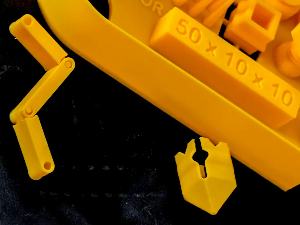
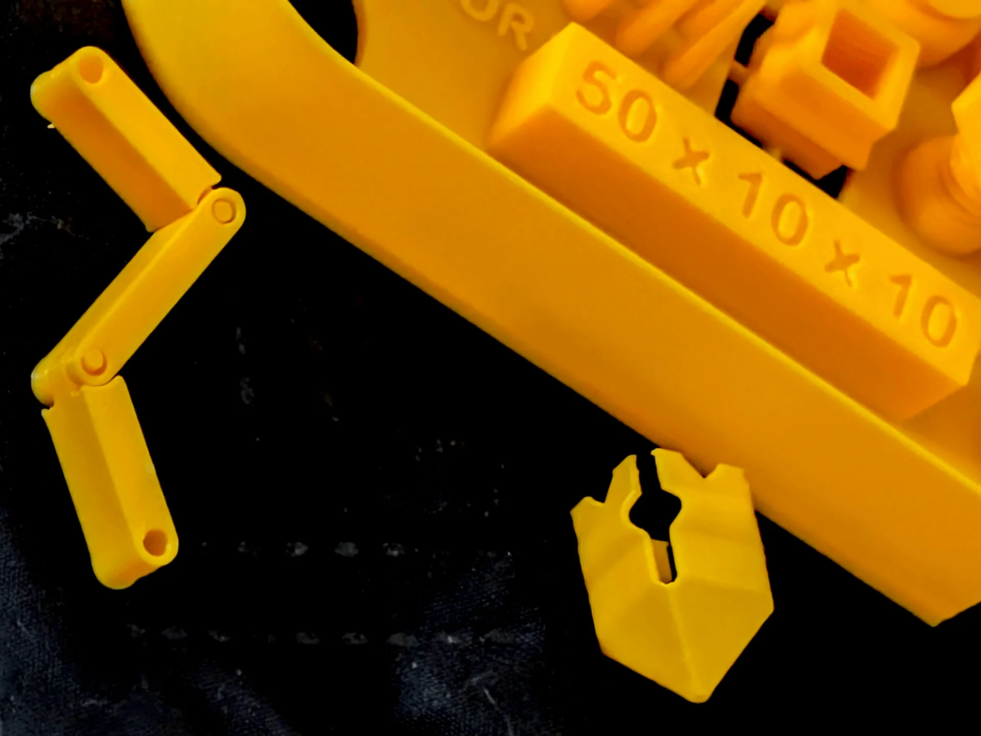
It's not the name of a rapper or a DJ, but the name of the "mechanical" innovation of the calibrator. Its shape and thickness are very unique and were specifically designed to be "easy" to print. The result should be a piece with properties that are elastic enough to be removed from the base without any effort (if your fingers aren't very fine, try using a simple tweezers, but don't force it. It should come out easily, despite the mechanical "block" caused by its particular shape).
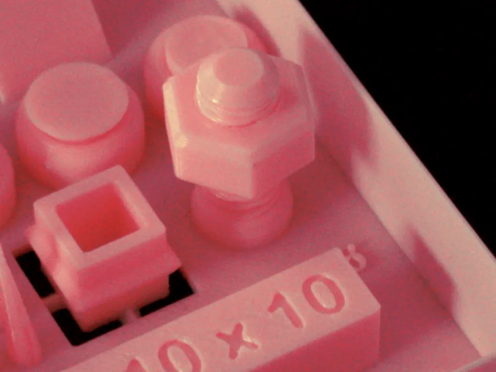
Bolt with its Nut:
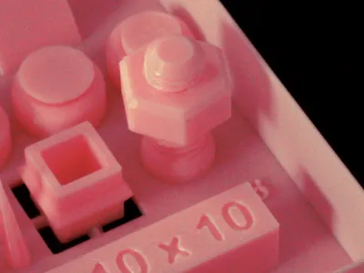
Here it is again, the essential bolt for testing the nut printed in the base circle. A well-calibrated printer should not cause any problems, so the nut should be easily screwed and unscrewed onto the bolt. The thread is standard, but the tolerance is approximately 0.2 mm between each wall, resulting in a total tolerance (circumference) of 0.4 mm. Some problems may arise from the overhang required by creating the nut thread and/or the bolt itself.
Parallelepiped dimensions:
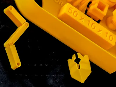
The block, as you can easily see, should measure 50 mm wide and 10 mm high and deep. Take the measurement, avoiding getting too close to the Base.
Hinge:
The other mechanical part of the Great Calibrator is this sort of "3-plate hinge" that can be used to test the possibility of performing some "on-plate direct printing" operations on mechanical parts. The plates that make up the hinge must be able to release with minimal effort and, once released, after a few bends to the left and right, they should have a fluid movement.
Finally, don't forget the writing on the base, which must be perfectly legible: “THE GREAT CALIBRATOR V1.0 BETA 04/2026" (yes... exactly, I started redesigning it in April lol)”.
Try it, send me the print results and let's compare them. Together, we'll find solutions to the most common 3D printing problems and, above all, let's make "THE GREAT CALIBRATOR" a unique and indispensable model for all enthusiasts.
THE GREAT CALIBRATOR REMAINS AND WILL REMAIN AN EXCLUSIVE FOR 3D PRINTERS BAMBULAB.
Happy printing, everyone!
What about offering me a coffee ?
https://buymeacoffee.com/menkheperra
License

You shall not share, sub-license, sell, rent, host, transfer, or distribute in any way the digital or 3D printed versions of this object, nor any other derivative work of this object in its digital or physical format (including - but not limited to - remixes of this object, and hosting on other digital platforms). The objects may not be used without permission in any way whatsoever in which you charge money, or collect fees.


Comment & Rating (6)