
Hart's A-frame - Educational Model
Print Profile(1)
Description
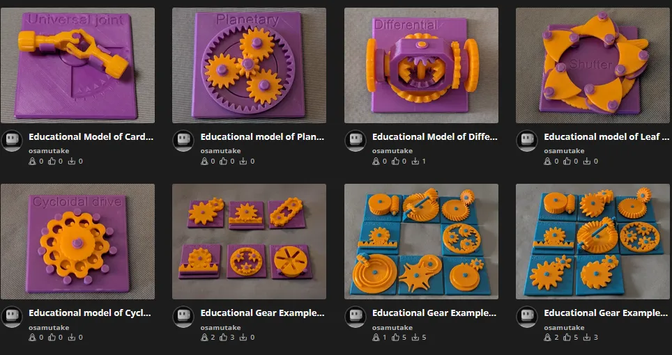
My Educational Mechanical Examples Series
This model is one of my educational mechanical mechanism examples on 80mm x 80mm base plates.
You can find all models of the series in this collection => [Mechanical Mechanism Examples]
The present model
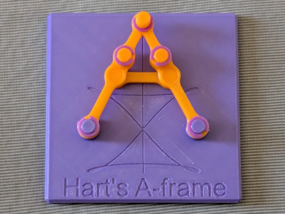
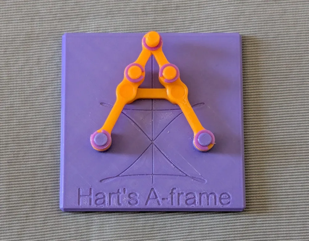
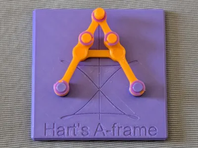
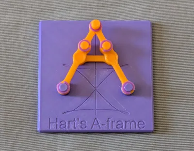
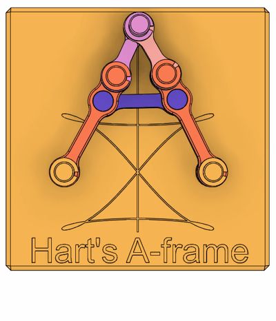
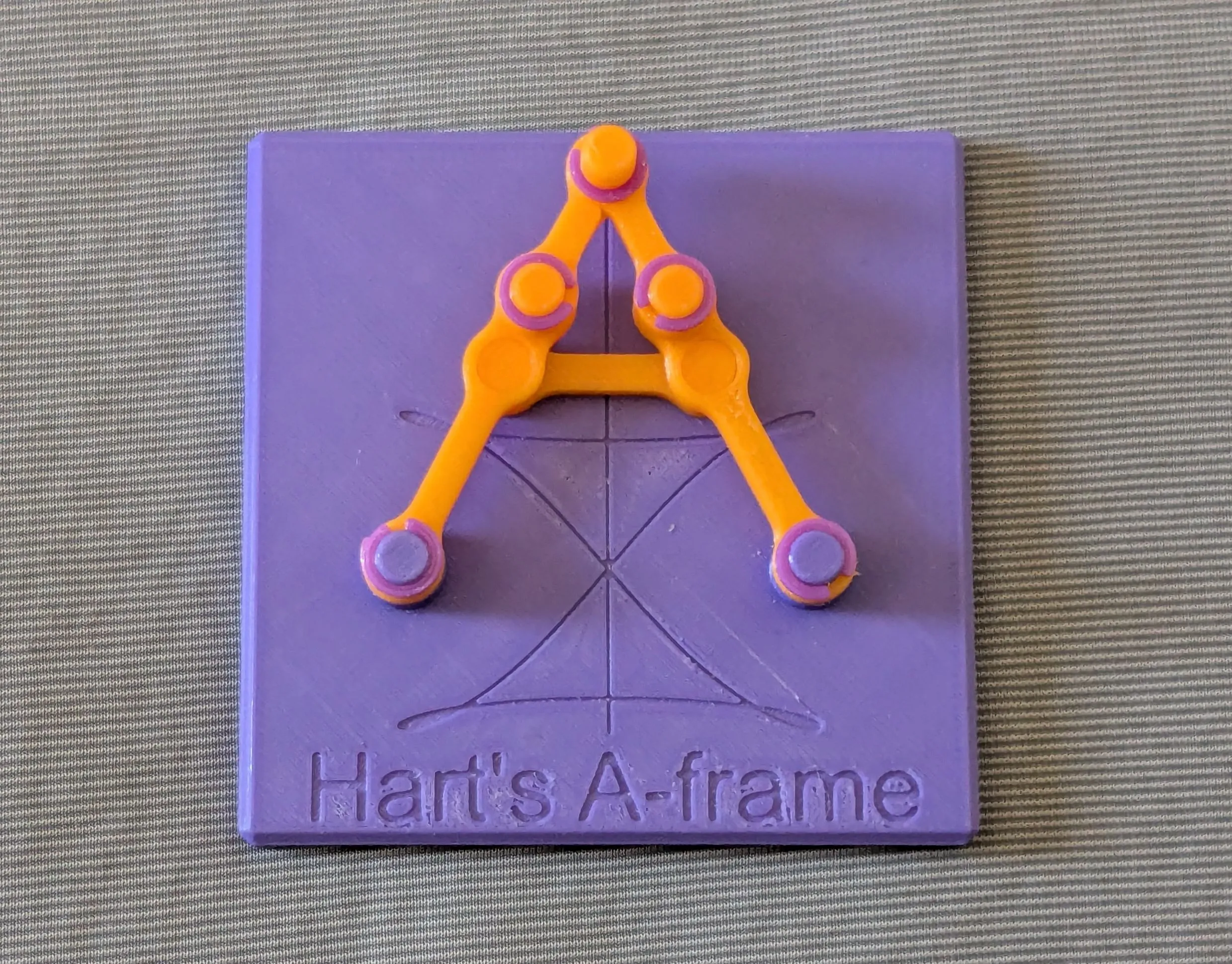
This is an educational model of a Hart's A-frame, which is one of the exact straight-line linkages.
Brief Description
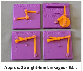
The approximate straight-line mechanisms introduced so far — Watt's linkage, the Chebyshev linkage, and the Grasshopper linkage — are all based on four-bar linkages. The coupler point need not lie at a joint between two links; it may sit at the midpoint of a link or on its extension. Even so, these simple linkages confine the coupler point to a path that is only approximately straight — and they do so without any linear guide or prismatic pair. A four-bar linkage, however, cannot trace an exactly straight line.


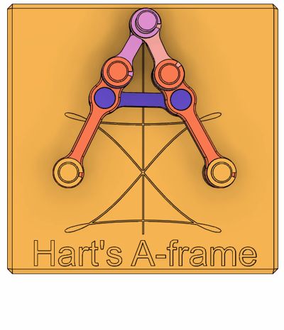


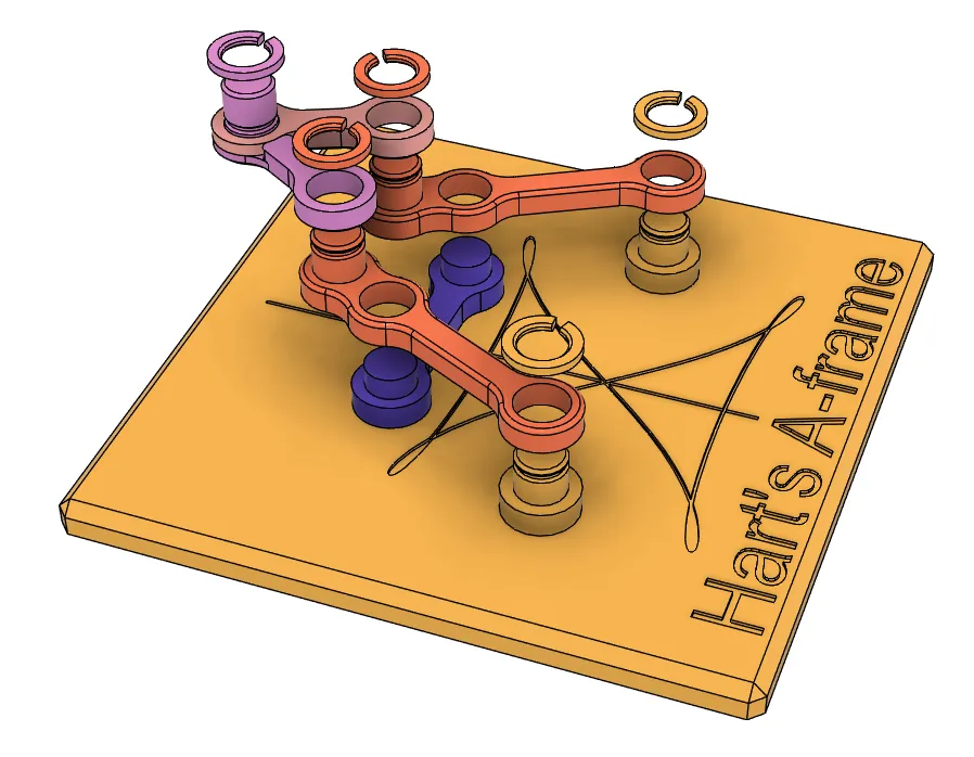
Hart's A-frame achieves exact straight-line motion by raising the number of links to six. Five of them move; the sixth is the base plate itself, which serves as the hidden ground link. Laid out as the capital letter A, each slanted side is built from a long link and a short link half its length, joined end to end, and the two short links meet at the apex. The lower end of each long link is pinned to the base plate, and these two fixed pivots are spaced apart by twice the length of the crossbar. The crossbar — the horizontal stroke of the A — joins the two long links at the points that divide them in a 3:1 ratio, with the longer portion toward the fixed pivot. Only these two lower pivots are anchored; every other joint is free to move. Under this arrangement the apex of the A, which is the coupler point, is constrained to travel along a perfectly straight line: the vertical line engraved on the base plate, which is the perpendicular bisector of the two fixed pivots. Move the coupler point by hand and you can feel it being held to this line.
As you play with the model, though, you will find that this is not the only path open to the coupler point: the motion branches at the midpoint between the two pivots. There, the coupler point can leave the straight line for a second, skewed path that traces a distorted triangle, also engraved on the plate. Pushing on the coupler point alone will not carry it past the corners of that triangle; there you must also control how the links fold in order to pass through. To keep the motion well-behaved, confine the coupler point to either the upper or the lower half of the straight line, or guide it through the midpoint so that it does not slip onto the other branch.
Reference
Related Models
Case
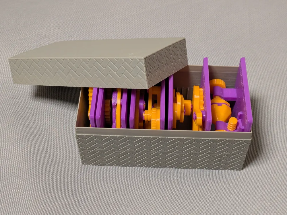
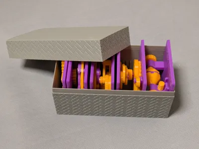
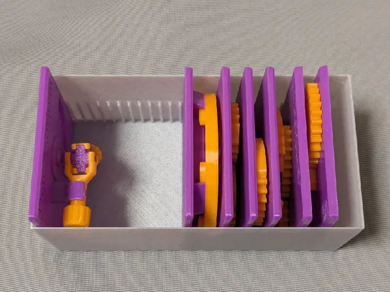
This model is compatible with the case included in my first set.
Printing
- Use the models named ???-printable.stl for printing.
The models named ???-assembled.stl are provided just to show how they should be assembled.
- Use well-dried PETG to have better dimensional accuracy.
- Use 0.1 mm or 0.08 mm layer height to have smoother surfaces.
- Use slow printing speed for overhangs.
- Select “Random” seam position to have smoother rotation.
Randomly distributed seam should be easily worn out after some wearing.Printing
Sanding and Filing
Note that, in this model, the rotation of the bases for bearings is intentionally made not too smooth.
Sometimes, the gears suffer from the stringing effect and/or elephant foot effect, resulting in a too tight fit to the shafts (they are designed with a 0.15 mm radial clearance).
If you see rough surface on the shafts due to stringing, sand off the roughness with a small piece of sand paper.
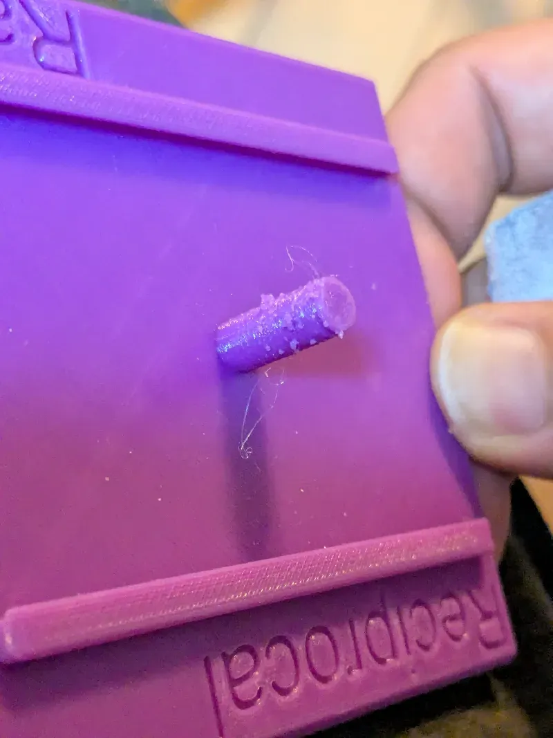
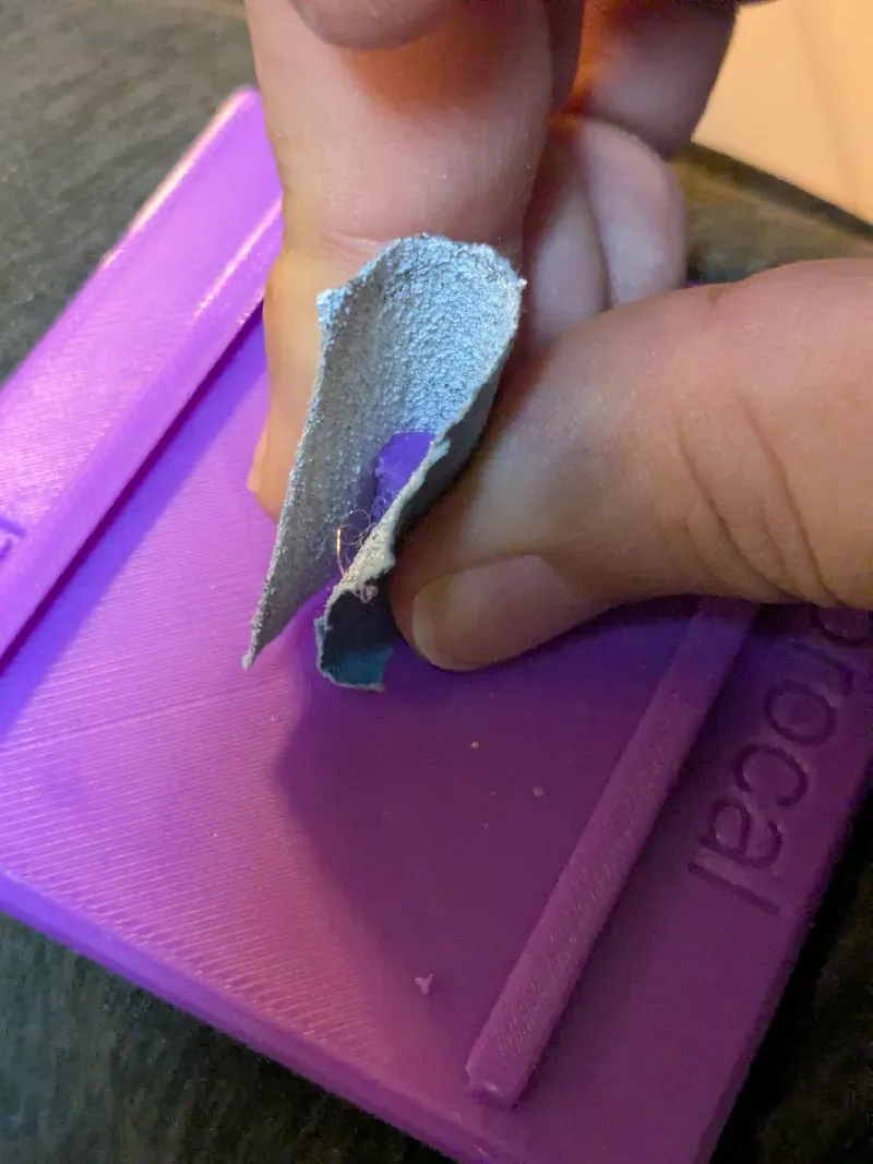
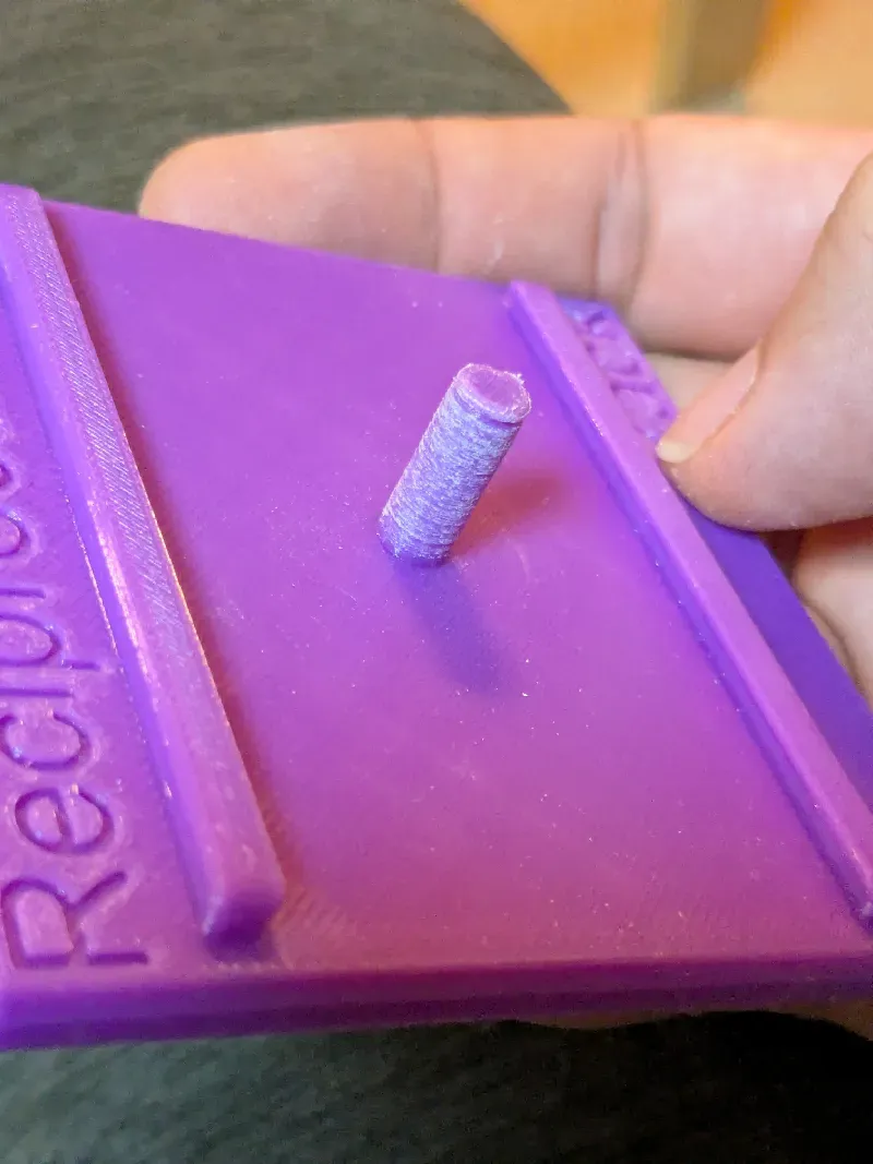
If you feel the gears do not rotate smoothly due to an elephant effect, widen the hole slightly by using a thin round bar file.
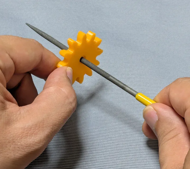
Without those issues, the parts should rotate very smoothly with minimal friction.
Assembly
Secure the links onto the shafts with the retaining rings.
Other examples
You may also be interested in the models in my educational mechanical mechanism examples.
Find them in this collection:
https://makerworld.com/collections/15048577-my-educational-mechanism-models
Happy printing!
Acknowledgement
I got into gears thanks to K.$uzuki's amazing articles and YouTube videos. Many of the mechanisms shown in this series came from the introductions on his website. He also makes excellent gear models himself. This series wouldn’t have existed without his inspiration.
I learned a lot about technical detail of designing gear tooth profiles from Haguruma-No-Hanashi website. I’m truly grateful for that.
License
- The 3D model(s) are licensed under Creative Commons Attribution 4.0 International.
- However, the text and images on this page are copyright reserved.
License



Comment & Rating (5)