100W FPV Battery PowerBank Module 6S


Print Profile(1)
Description
Membership
💼 Commercial use: If you wish to manufacture this product commercially, I have added a commercial subscription. With an active subscription, you will have the right to legally sell my models and simultaneously support me as a developer. You can also get a commercial subscription simply for support
Boost Me (for free)
Please support my work 💪
For you, this model downloads in seconds, but for me, it represents weeks of work after my main job.
Creating such models takes a lot of time, so your “Boost” costs you nothing but helps me immensely to continue developing projects.
And for those who want to support even more, go ahead
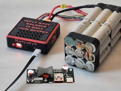
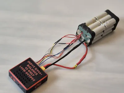
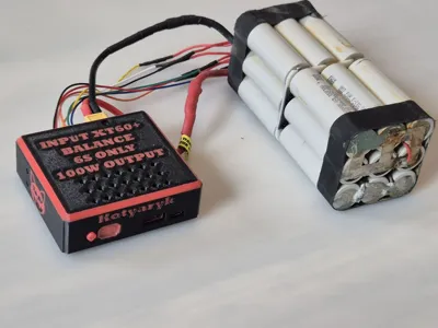
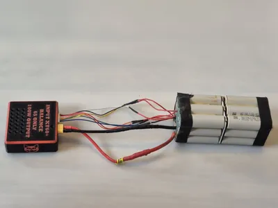
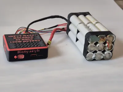
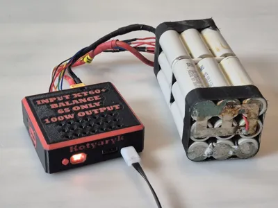
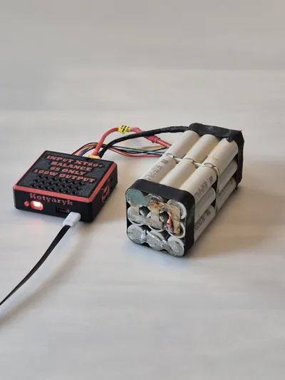
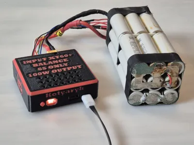
⚡ 100W FPV Battery PowerBank Module (2S–6S)
Transform a regular FPV battery into a compact portable power bank 🔋
The main advantage of this version is its affordable price. While building my 140W version,
its link https://makerworld.com/en/models/2842849-140w-fpv-battery-powerbank-module-6s#profileId-3169519
usually costs approximately 40€, this model can be assembled for about 20€, depending on the cost of components in your region
The module allows charging:
📱 Smartphones
💻 Laptops
📡 Starlink Mini
🔦 Flashlights
🛠️ Other USB-C and PD devices
🔧 Features
✅ Up to 100W power
✅ Bidirectional charging
✅ Supports Li-Ion, LiPo, and LiFePO4
✅ USB-C Power Delivery
✅ Digital indicator
✅ Printed button for convenient control
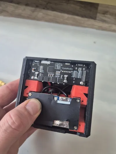
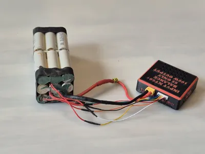
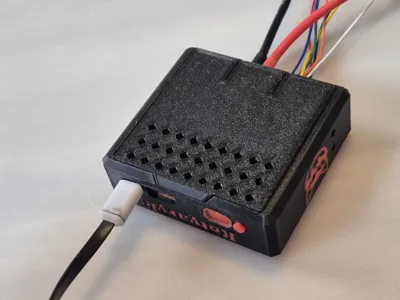
✅ Compact and repairable design
🔋 2S–6S Battery Support
The board itself supports batteries from 2S to 6S
However, the actual configuration depends on the board's settings and the installed BMS. For example, if a 6S BMS is used, the system will only work with 6S batteries
🔋 BMS Support
The model was developed for the BMS I used in my build
However, you can use other BMS boards
If your BMS has different dimensions, it is usually enough to just change the shape of the spacer (adapter) for the BMS without altering the main case design
❄️ Cooling
If possible, I recommend installing additional cooling
During tests, no critical overheating or emergency shutdowns were observed, but the board can get quite hot under load
A small heatsink or active cooling can positively affect the device's durability and stable operation
⚠️ My User Experience
Two identical boards were purchased for testing
One works without any issues
The second one behaved unstably from the very beginning. Sometimes after connecting the battery, it was necessary to first connect the balance connector, and then the XT60. Occasionally, the XT60 had to be reconnected repeatedly for the board to start
After about a week of operation, this same board stopped supplying power to external devices, although it continued to charge the battery via USB-C
I cannot say for sure what the cause was. Perhaps it was simply a defective unit, as the second board from the same order works correctly
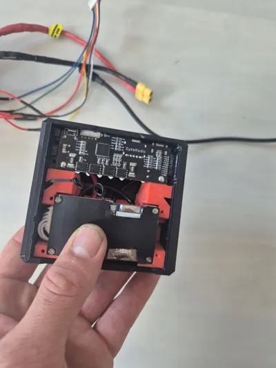
⚠️ Note on the 10 kOhm Resistor
On the problematic board, I had to replace one of the 10 kOhm resistors in the location shown in the photos

After that, its operation became much more stable
As far as I could ascertain, this node is related to the board's temperature control, which can sometimes mistakenly trigger protection when connecting high-capacity batteries
It is important to understand that such a modification effectively disables the board's built-in thermal protection
However, battery protection is usually still provided by the installed BMS
If your board works normally, I do not recommend performing this modification
⚠️ Board Setup Before First Power-Up
Before connecting the battery, be sure to check the jumper settings on the board
🔋 Number of Cells (S)
Jumpers for selecting the number of battery cells are located at the bottom of the board
If you are using:
• 2S — short the 2S jumper
• 3S — short the 3S jumper
• 4S — short the 4S jumper
• 5S — short the 5S jumper
• 6S — short the 6S jumper
If your board comes with a different configuration soldered from the factory, you need to desolder the factory jumper and solder the correct one
⚡ Charging Voltage
Above the cell count selection jumpers are jumpers that set the maximum charging voltage
For Li-Ion batteries, you must set 4.2V
Before the first power-up, be sure to check both settings, as an incorrect configuration can lead to improper board operation or incorrect battery charging
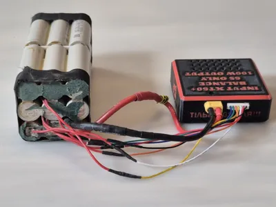
📦 Components / BOM
| Component | Quantity | Note | Link |
|---|---|---|---|
🔋 100W USB-C PD Board
| 1x | Main bidirectional charge/discharge module | 100W PD PowerBank Board |
⚡ 6S BMS with balancing
| 1x | 15A–25A version | 6S BMS Board |
🔌 XT60 Connectors
| 1x | Amass XT60 Male/Female | Amass XT60 Connectors |
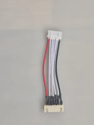
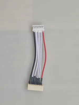
🔗 JST-XH 7Pin Balance Connector
| 1x | For 6S balancer | JST-XH 7Pin Connector |


⚠️ Important
❗ Use only if you understand working with LiPo/Li-Ion batteries
❗ Always check polarity before connecting
❗ Do not leave batteries unattended during charging
❗ Use this project at your own risk
This project was created as a compact and powerful field power source for FPV batteries 🚀
💬 As always, I welcome your feedback and finished builds
Happy printing
License
You shall not share, sub-license, sell, rent, host, transfer, or distribute in any way the digital or 3D printed versions of this object, nor any other derivative work of this object in its digital or physical format (including - but not limited to - remixes of this object, and hosting on other digital platforms). The objects may not be used without permission in any way whatsoever in which you charge money, or collect fees.
Comment & Rating (2)