Search models, users, collections, and posts

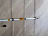
Stowable Portable Yagi Antenna
IP Report
Print Profile(1)
0.2mm layer, 2 walls, 100% infill
Designer
2.3 h
1 plate
Open in Bambu Studio
Boost
4
8
2
0
2
1
Released
Description
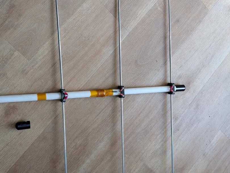
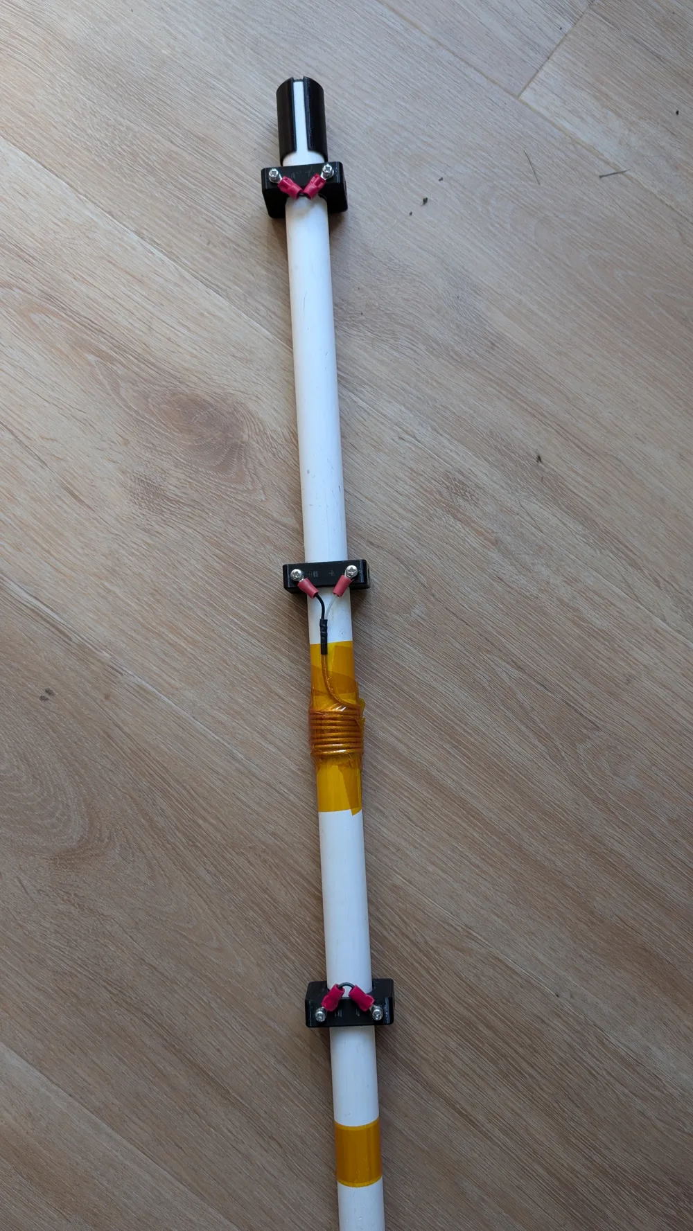
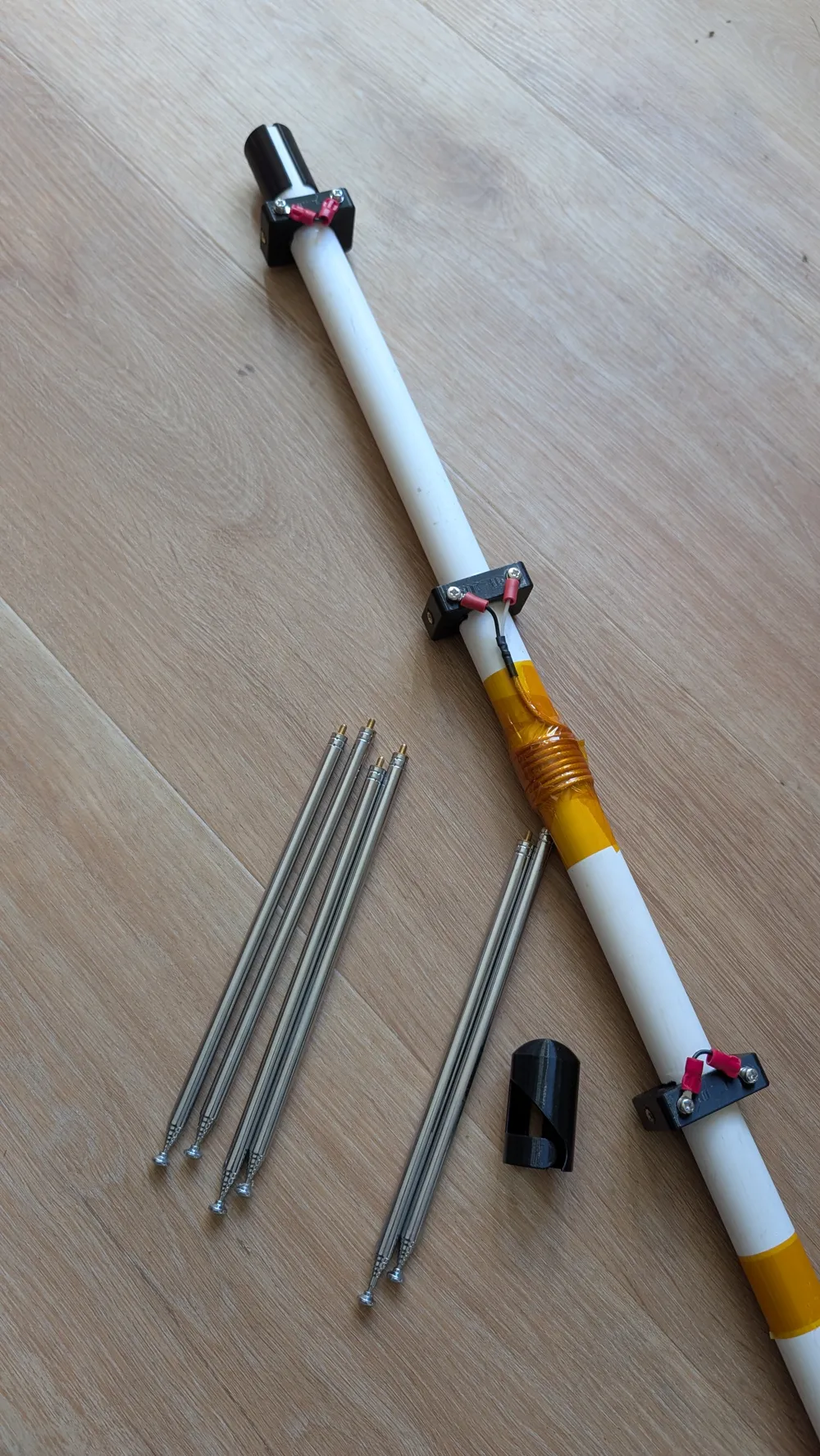
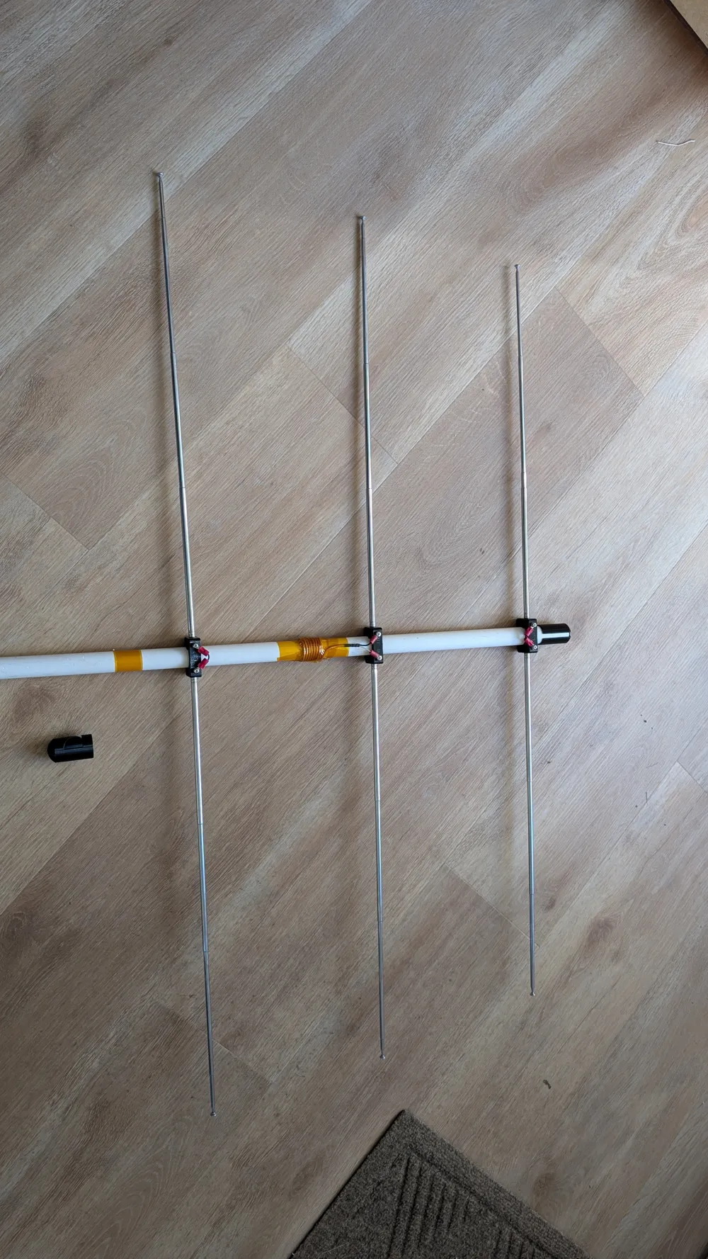
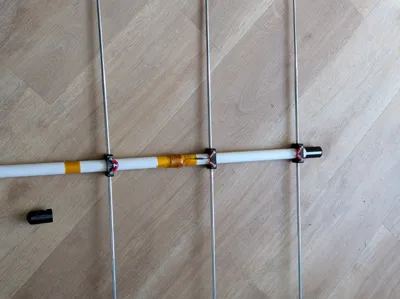
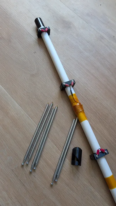
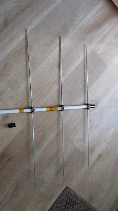
Printable parts for a 3 element Yagi antenna.
- All parts sized for ½ inch PVC pipe.
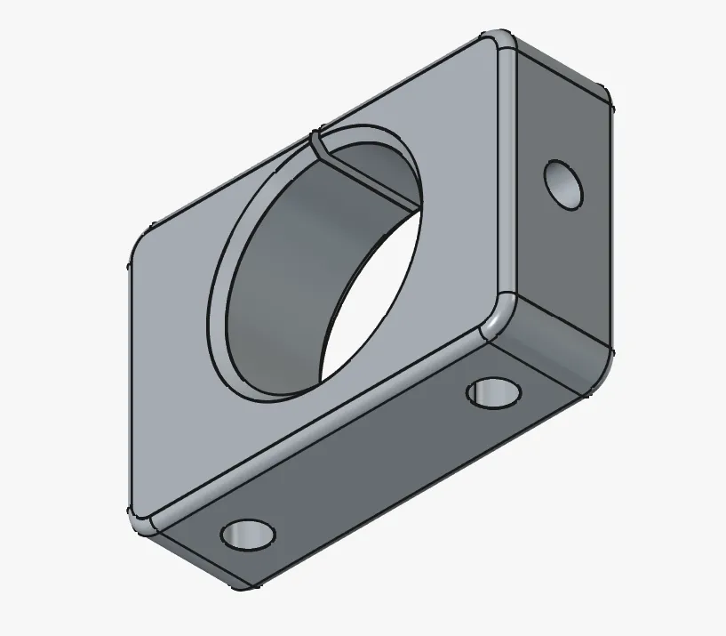
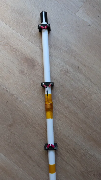
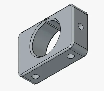
- Brackets take M3 Brass thermal inserts. Be sure to solder a short length of wire before you press the insert into the part. The solder the wire end to the second insert. Repeat for two total wire/insert sets per bracket.
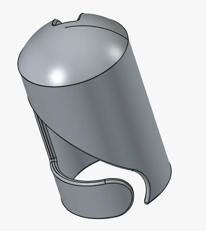
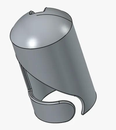
- End caps are easily removable by flexing the finger to disengage the pin from a 6mm (¼ inch) hole drilled into the PVC pipe 30mm from the end (drill center).
- The end caps have a slot cut down them to allow storage of BNC connector inside the PVC pipe.
- Antenna elements are available on Amazon. These easily store inside the pipe with both end caps in place.
Tuning will vary by application. General case:
- Tune driven elements first. End to end length is the baseline half wavelength (0.5 lamda)
- Using the half lamda as a reference of 0.5 wavelength, position both the director and reflector brackets 0.2 wavelengths above and below the driven elements.
- Set the reflector at 5% longer than the driven element.
- Set the director at 5% shorter than the driven element.
- Add short wire jumper across the brackets for both the reflector and director elements.
- You may want to implement a hairpin matching loop on the driven element, I didn't feel the need with SWR at 1.5.
License

This user content is licensed under a
Creative Commons Attribution-Noncommercial-Share Alike


Comment & Rating (2)