
Operating Model of Robertson's/Bourn Windmill
Print Profile(1)
Description
Description:
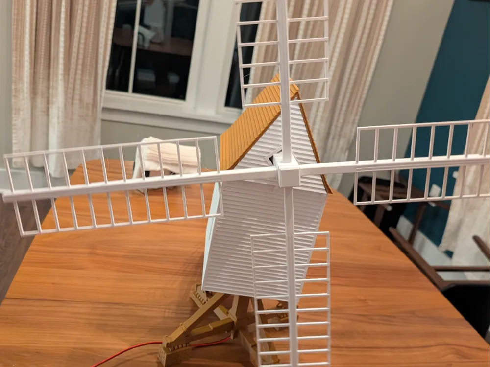
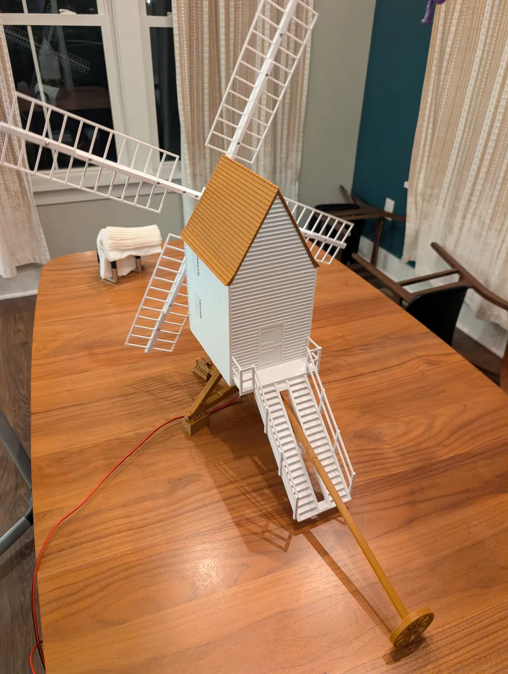
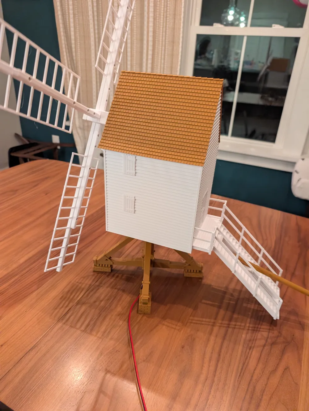
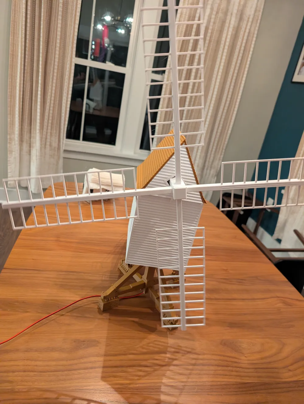
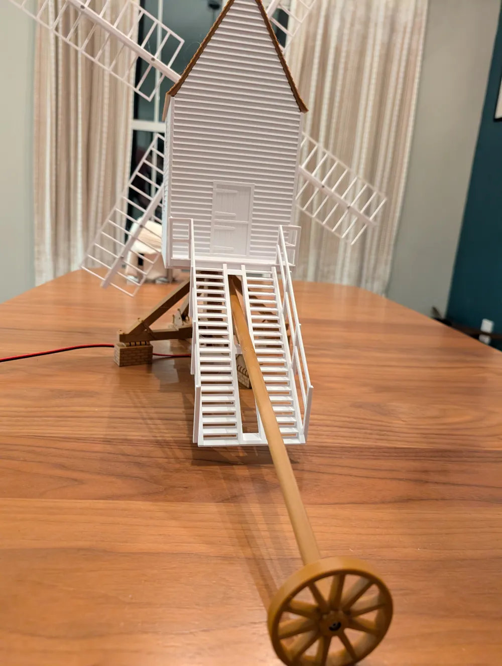
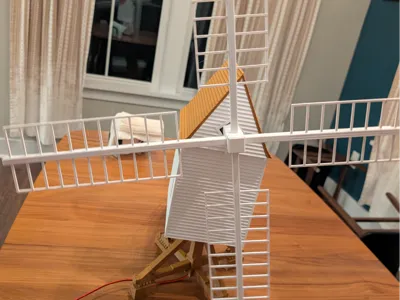
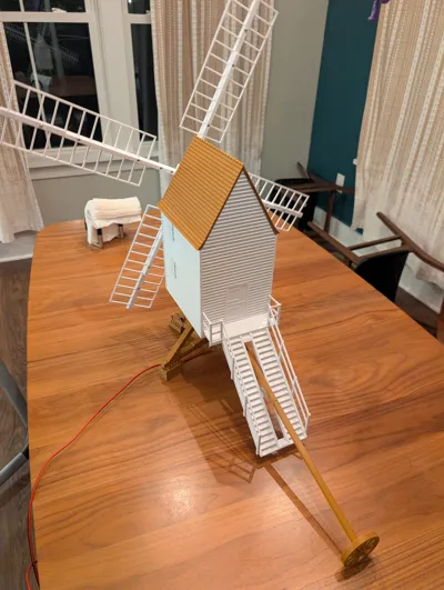
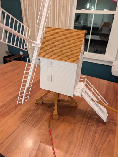
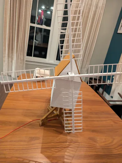
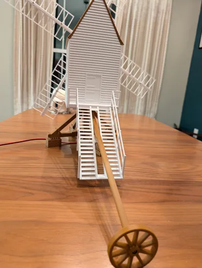
A approximately 1:25 scale rendition of an early 18th century English open trestle post windmill. This model in particular is based upon the replica Robertson's Windmill at Colonial Williamsburg, Virginia, USA which is itself a replica of the oldest existing windmill in England, the Bourn Windmill built in 1636. It is scaled to appropriately fit in with G gauge or 1 gauge trains, and is of a similar size to Piko and Pola buildings.
A motor can be added to spin the blades. For safety the blades are not directly attached to the motor but rather through a crenelated magnetic clutch assembly that will separate if the blades are stopped and should save the motor from burning out. I added this as I have small children who I expect to be tempted to grab the blades.
Hardware Requirements:
- 4 total m3 x 6 mm button socket cap machine screw
- 4 x 1 Whip front to back
- 27 total m3 x 10mm button socket cap machine screws
- 6 x bottom to body
- 6 x motor to motor mount
- 6 x motor mount to body
- 18
- 3 x porch to body
- 21
- 4 x 2 spar to hub
- 25
- 8 total m3 x 12mm button socket cap machine screw
- 4 x 2Spar to Whips
- 1 total m3 x 14mm button socket cap machine screw
- 1 Tailwheel to tail
- 4 total 20mm Bore x 32mm OD x 7mm Thickness bearings (6804ZZ)
- If motorizing
- 8 total 6 mm x 3mm round neodymium magnets
- CA (cyanoacrylate) glue for attaching magnets
- 1 total DC 24V 50RPM 37mm diameter gearbox
- At least 1 meter/yard of 1mm-1.5mm (18 gauge - 16 gauge) speaker wire
Assembly:
These instructions assume you are installing the motor. You may ommit the motor, wiring, and magnet clutch steps if not.
Identify the poles of the neodymium magnets. Then glue 4 of the magnets into the hub, taking care they are all oriented the same with respect to polarity; use CA glue to affix.
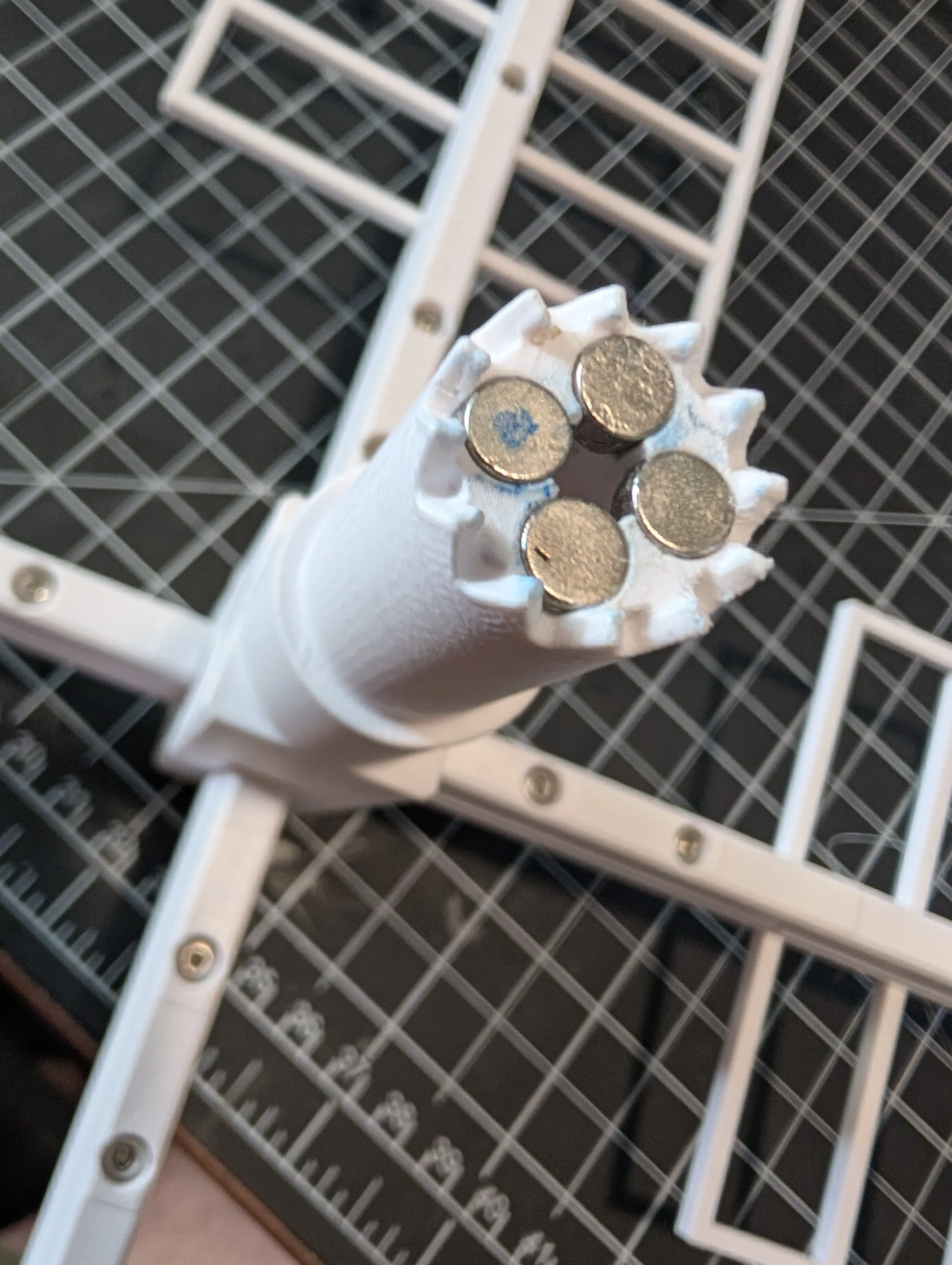
- Glue the remaining 4 magnets into the motor clutch, again all oriented the same, but ensuring the are the opposite polarity of the hub. These magnets pull the two halves of the clutch together.
Attach the spars to the hub with 8 m3 x 10mm screws.
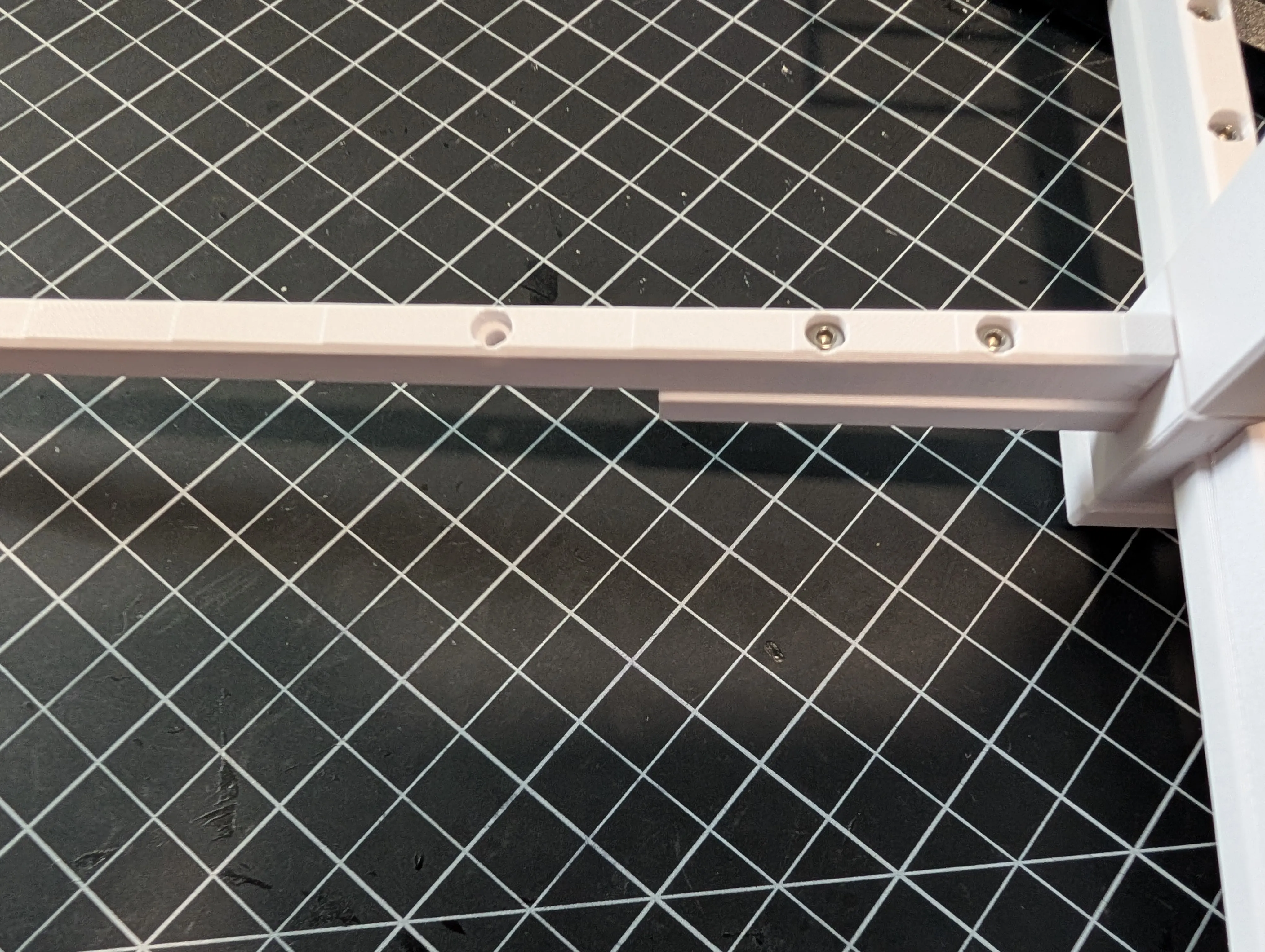
Attach the whip/blade fronts to backs with 4 m3 x 6mm screws.
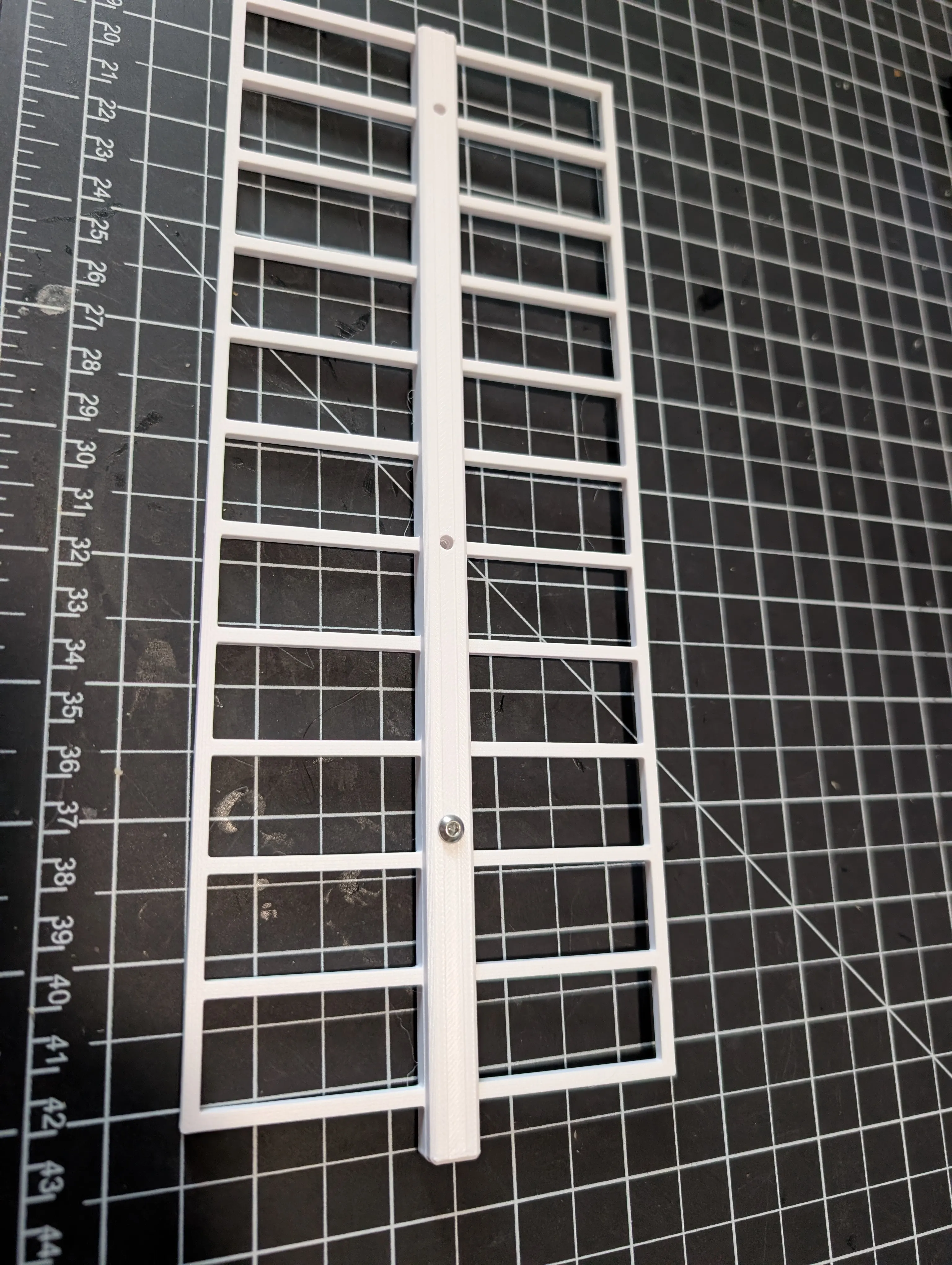
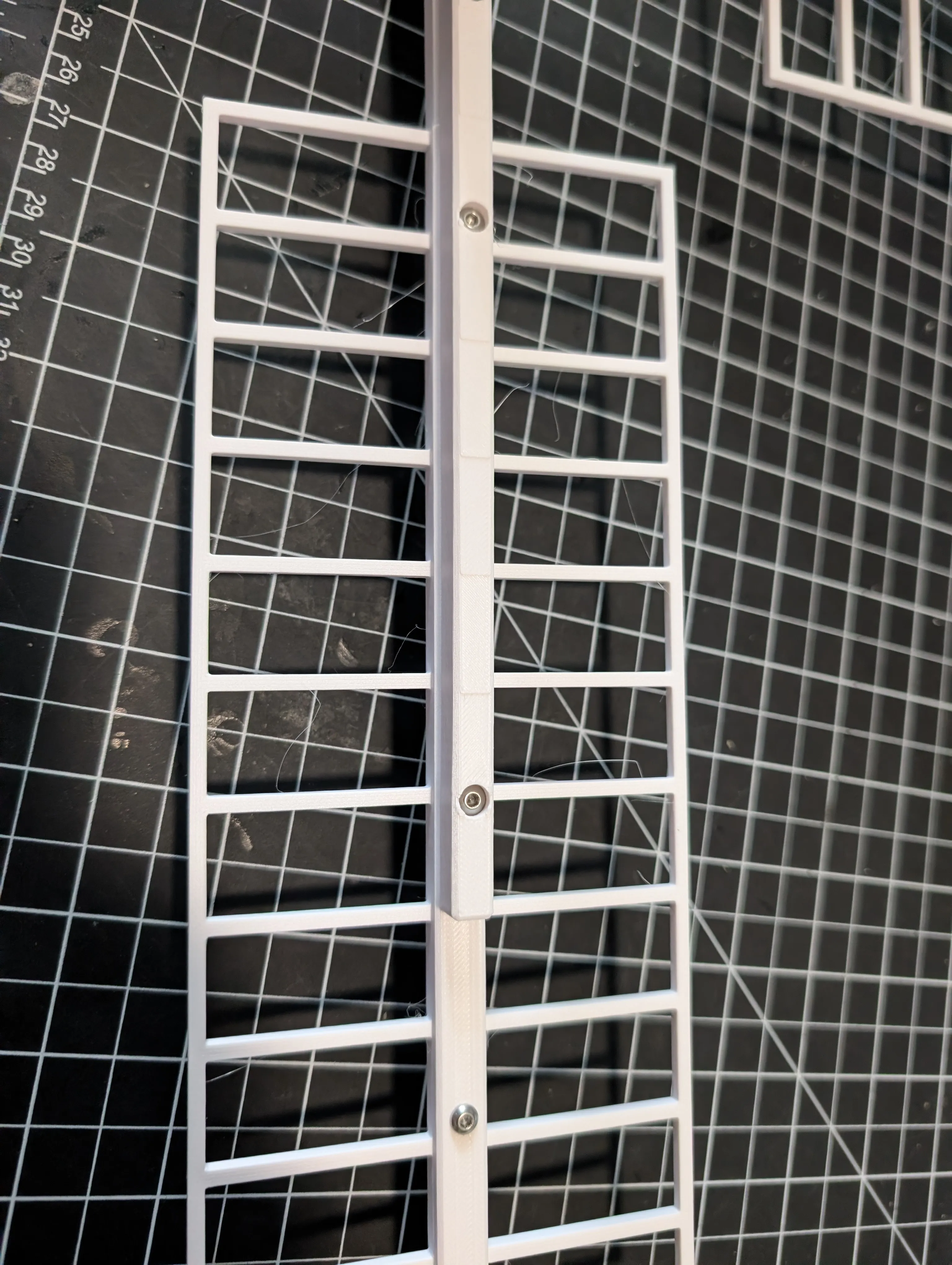
Attach whip/blades to spars with 8 m3 x 12mm screws.
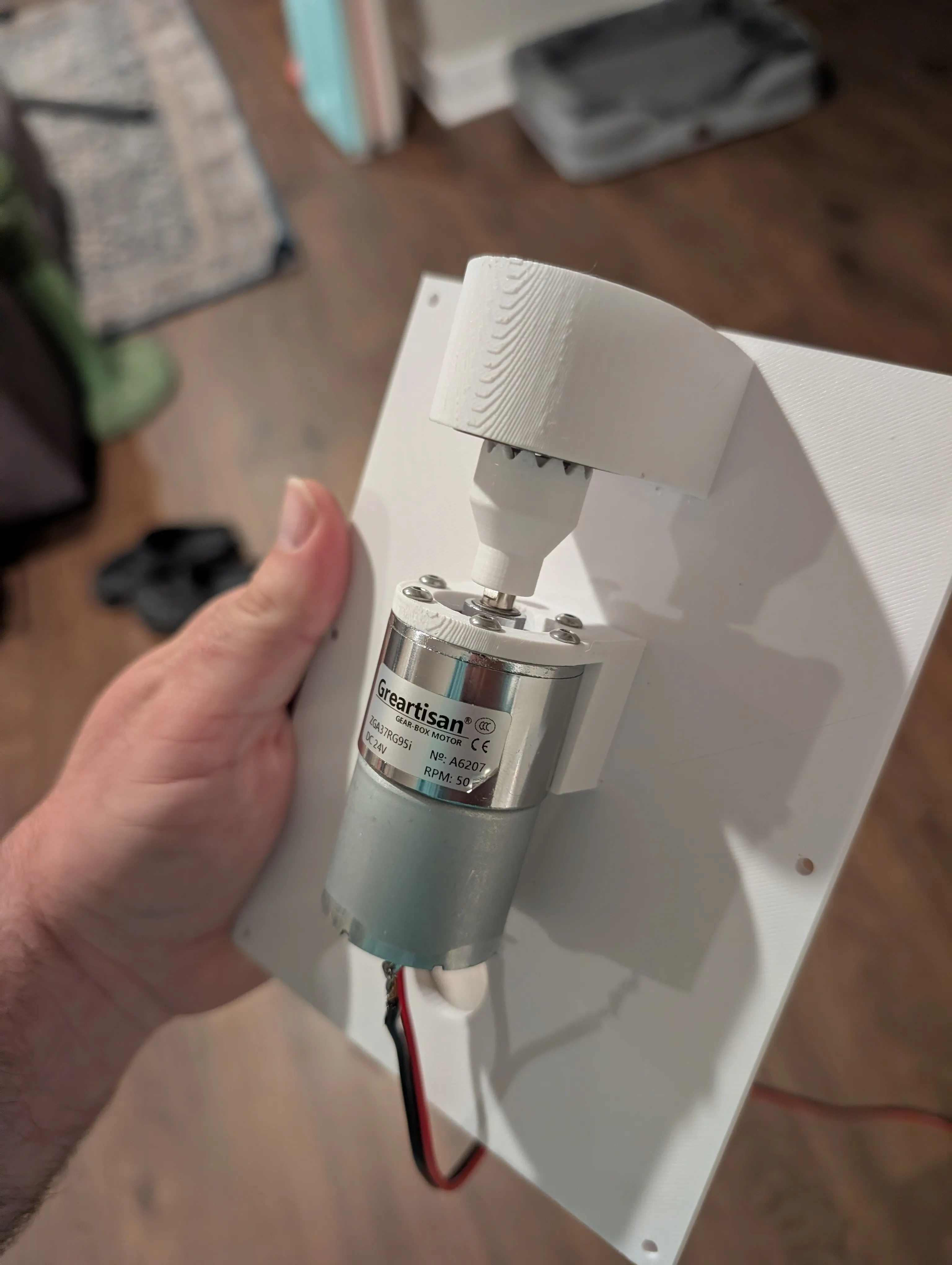
- Firmly press fit (by hand) the clutch onto the motor hub.
- Firmly press 2 bearings into the bearing mount on motor mount plate.
- Install motor on the motor mount plate with 6 m3 x 10mm screws.
Solder wire to motor leads
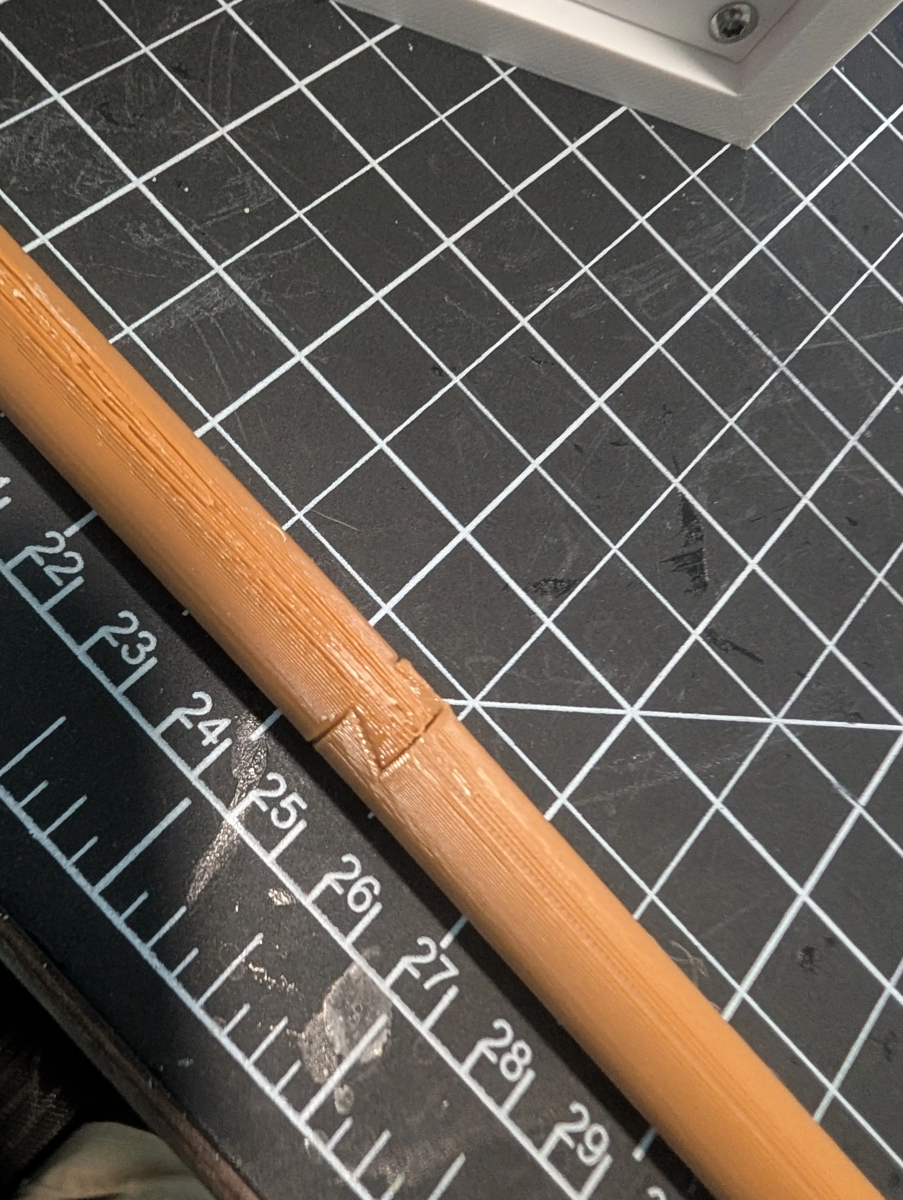
Glue together two haves of “tail” using the sliding dovetail.
Glue stair handrails to stairs.
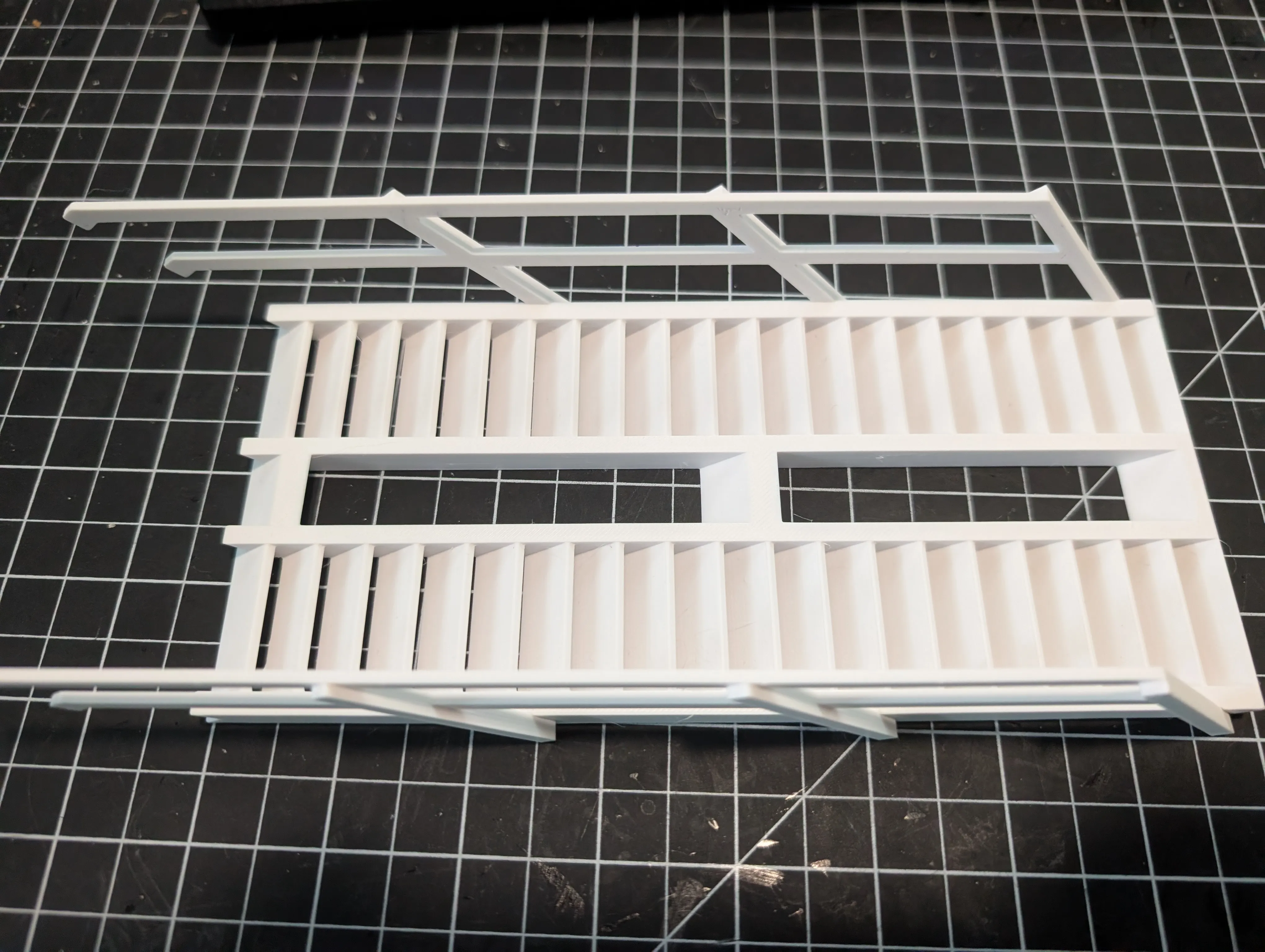
- Glue deck handrails to deck.
- Glue the front and rear peak of the body to the main body. The rear peak without a large square hole goes on the side of the body with the door.
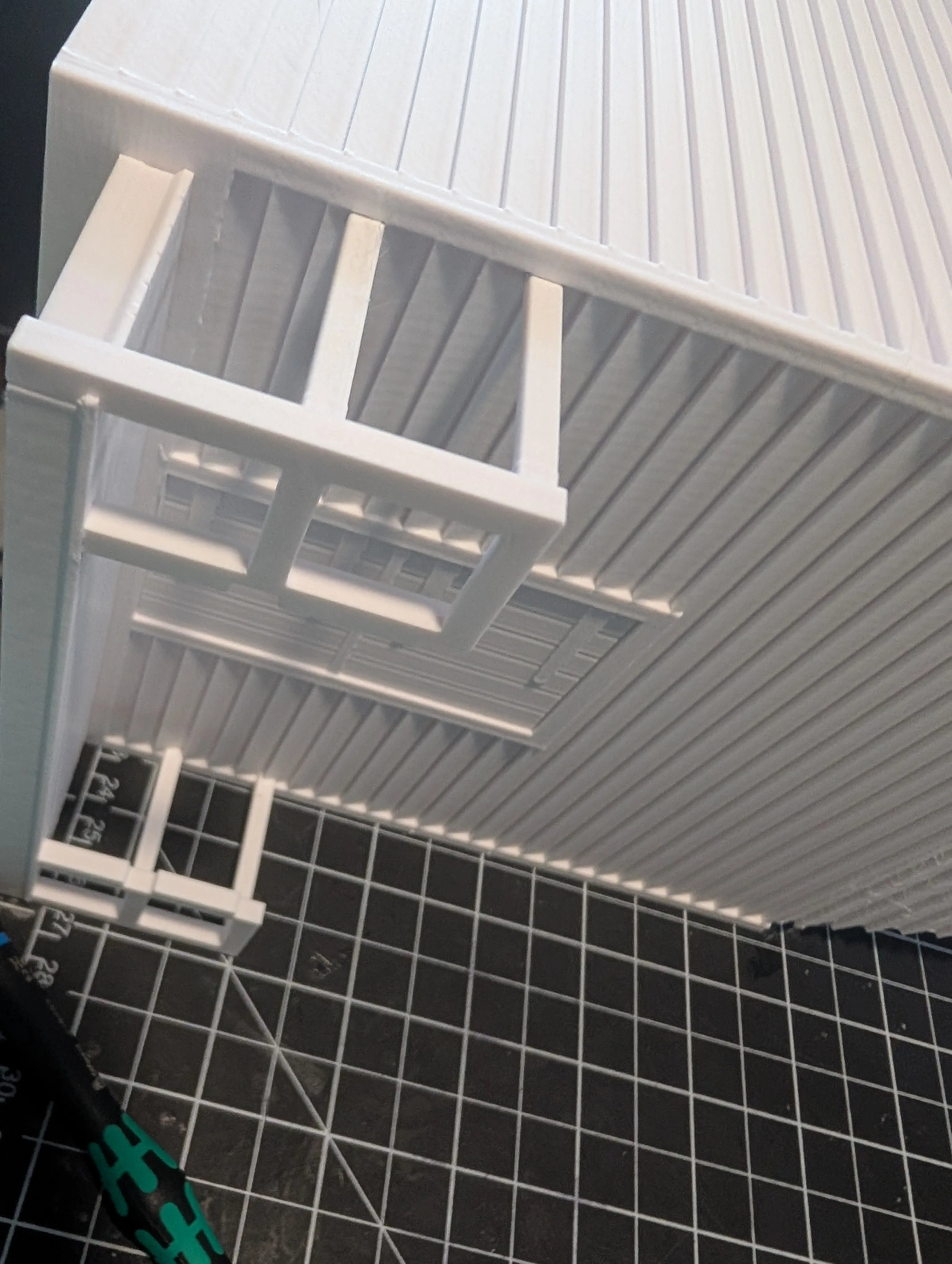
Attach deck to body using glue for handrails and 3 m3 x 10mm screws
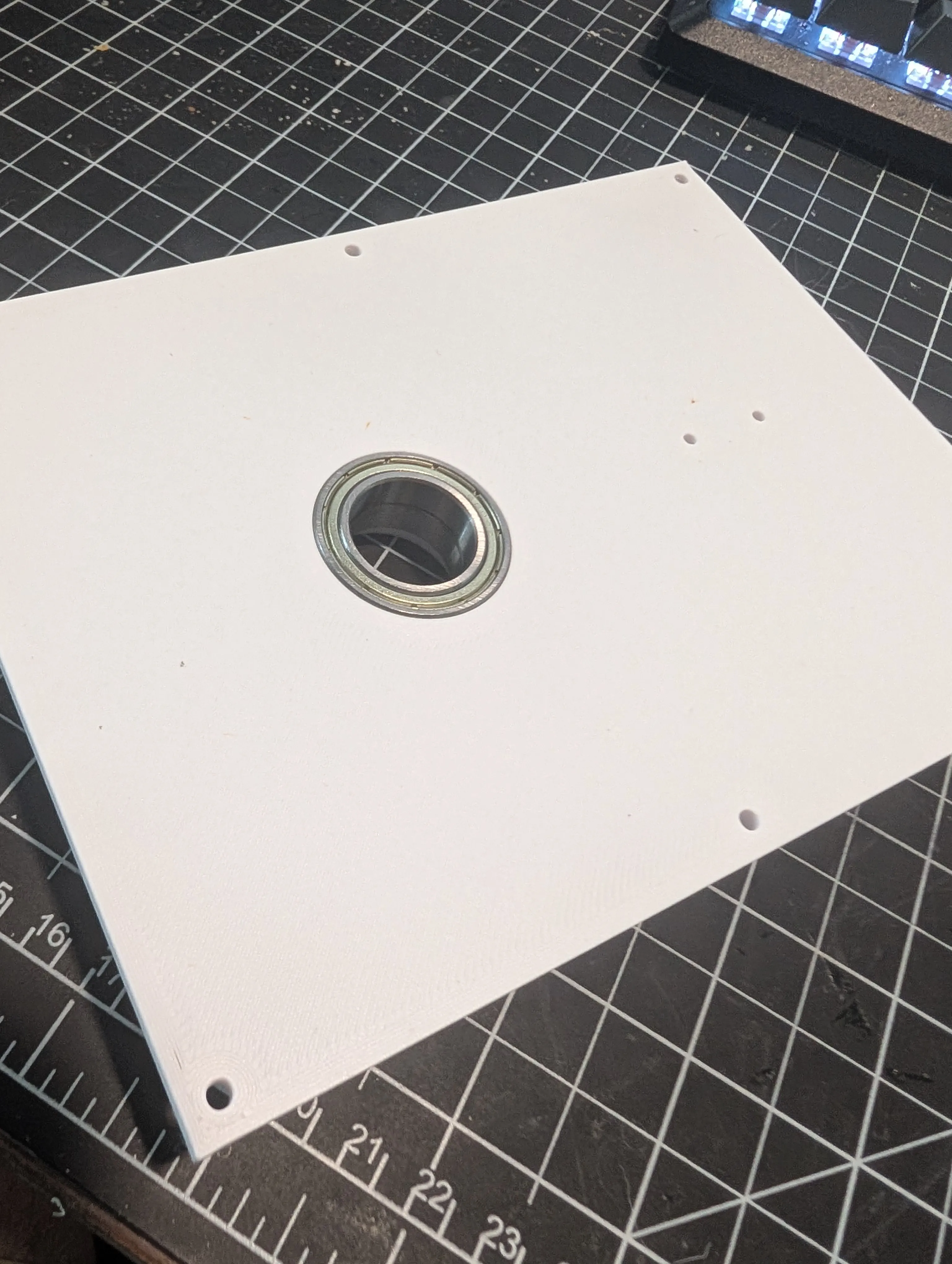
Firmly press 2 bearings into the well in the bottom floor plate.
Install the tail to the floor plate with 2 m3 x 10mm screws.
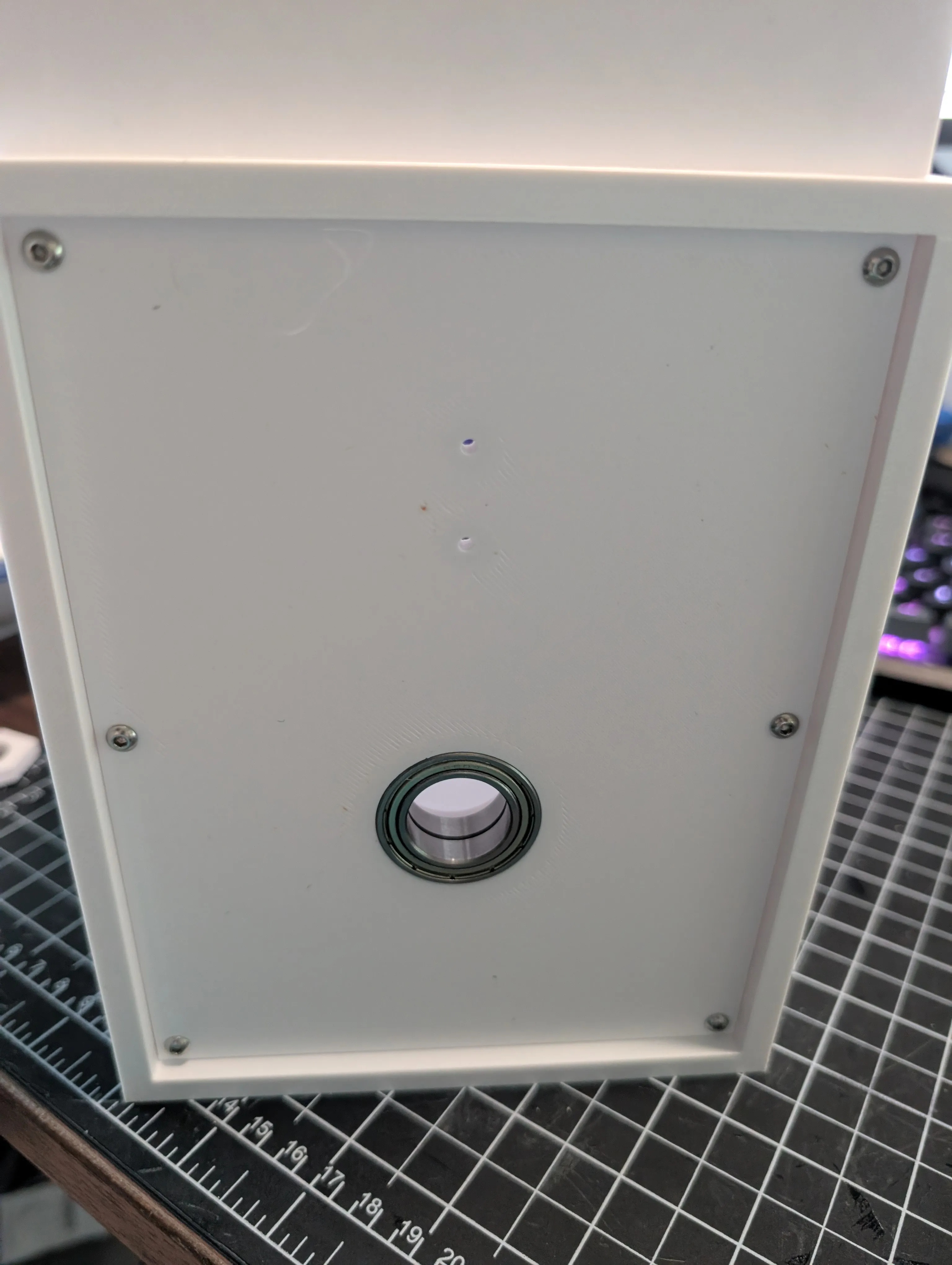
- Slip the post base into the floor plate bearings and lock in place with the printed nut. Don't overtighten so that the plate may rotate freely.
- Attach the floorplate to the body with 6 m3 x 10mm screws.
Slide the stairs into place, guiding the tail through the upper hole. You will need to glue it to the deck and handrails. The fit was designed to be tight enough to hopefully not need significant clamping.
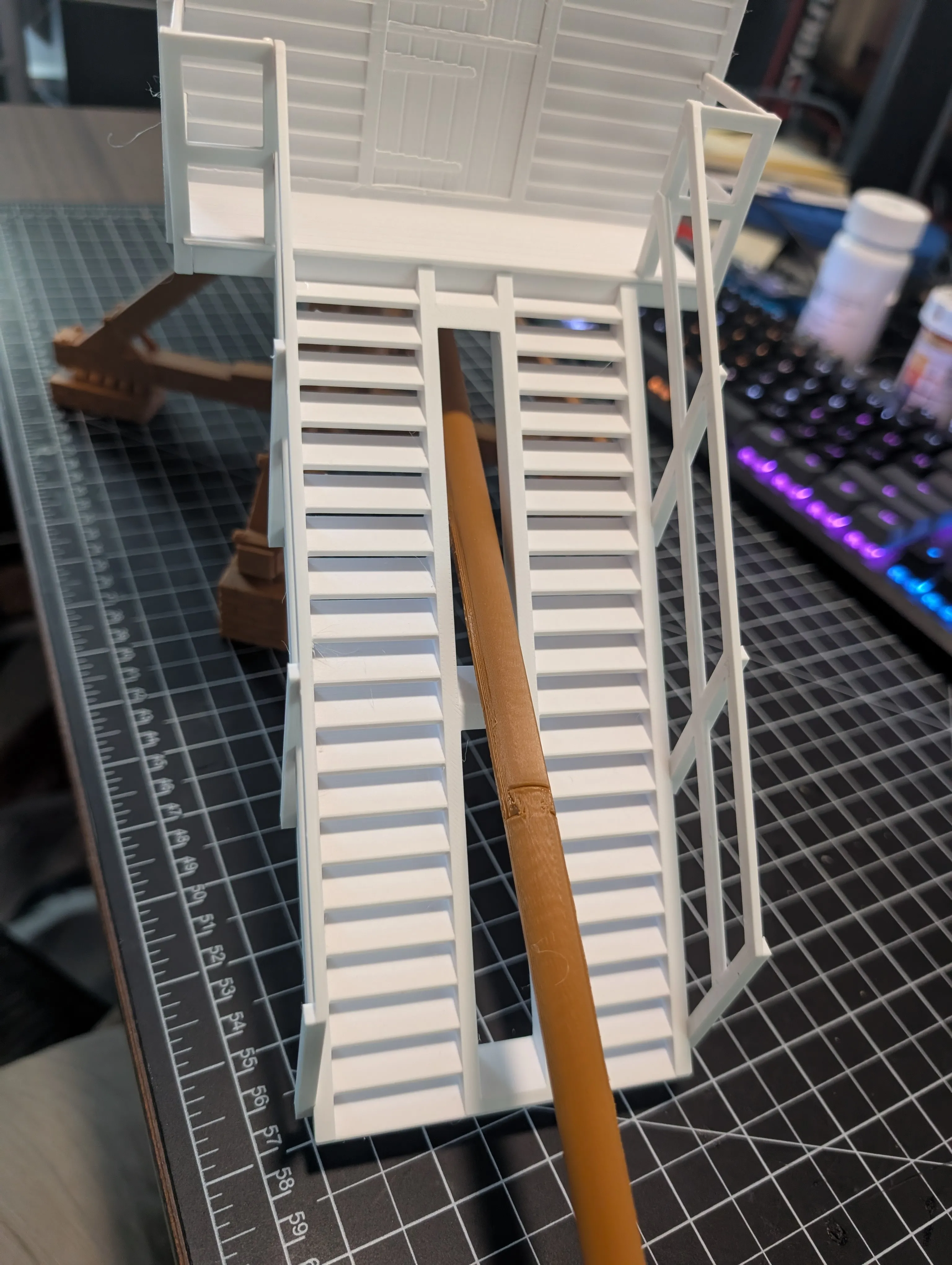
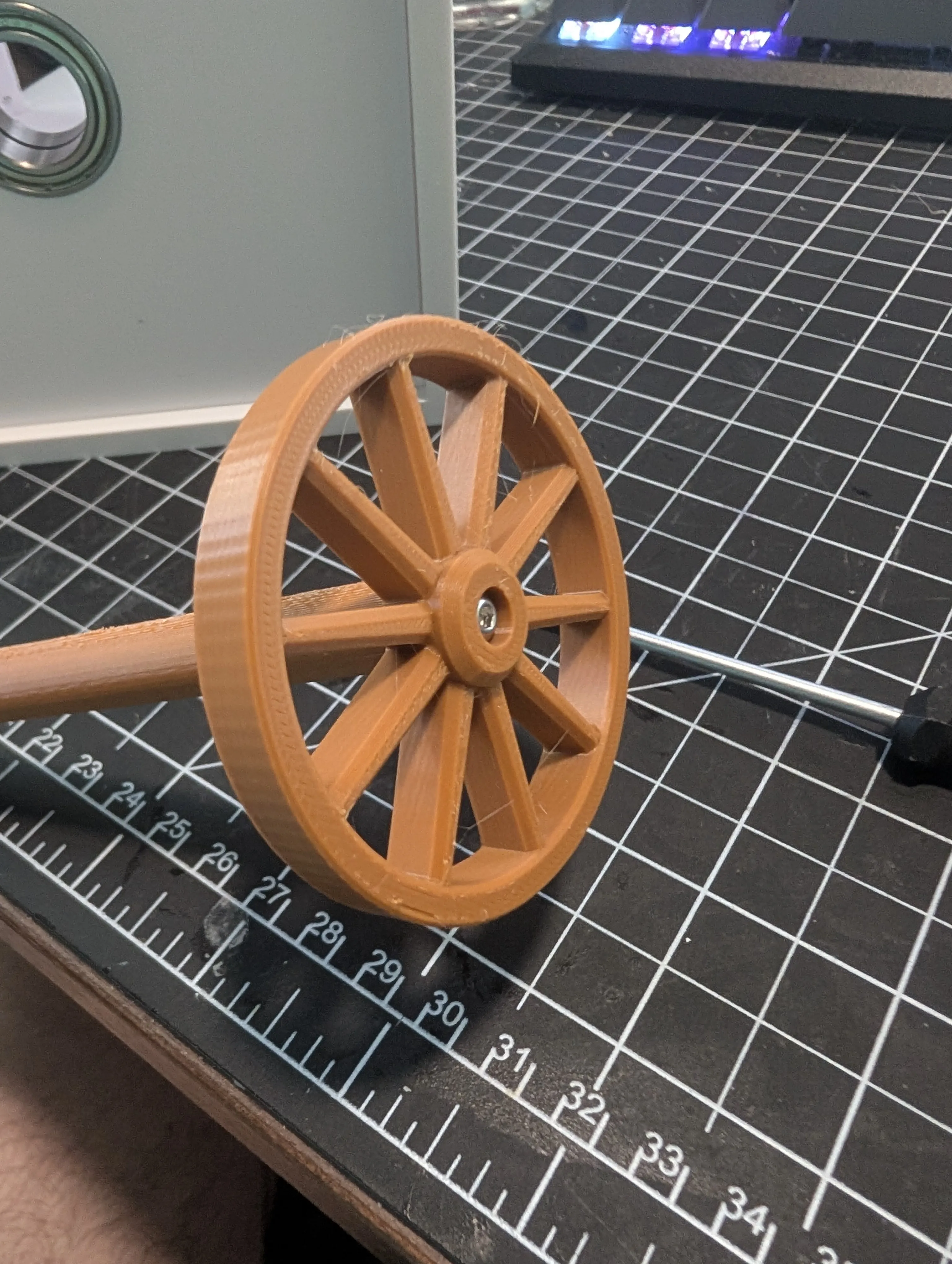
Attach the tail wheel to the tail with 1 m3 x 14mm screw. Don't overtighten to allow it to freewheel.
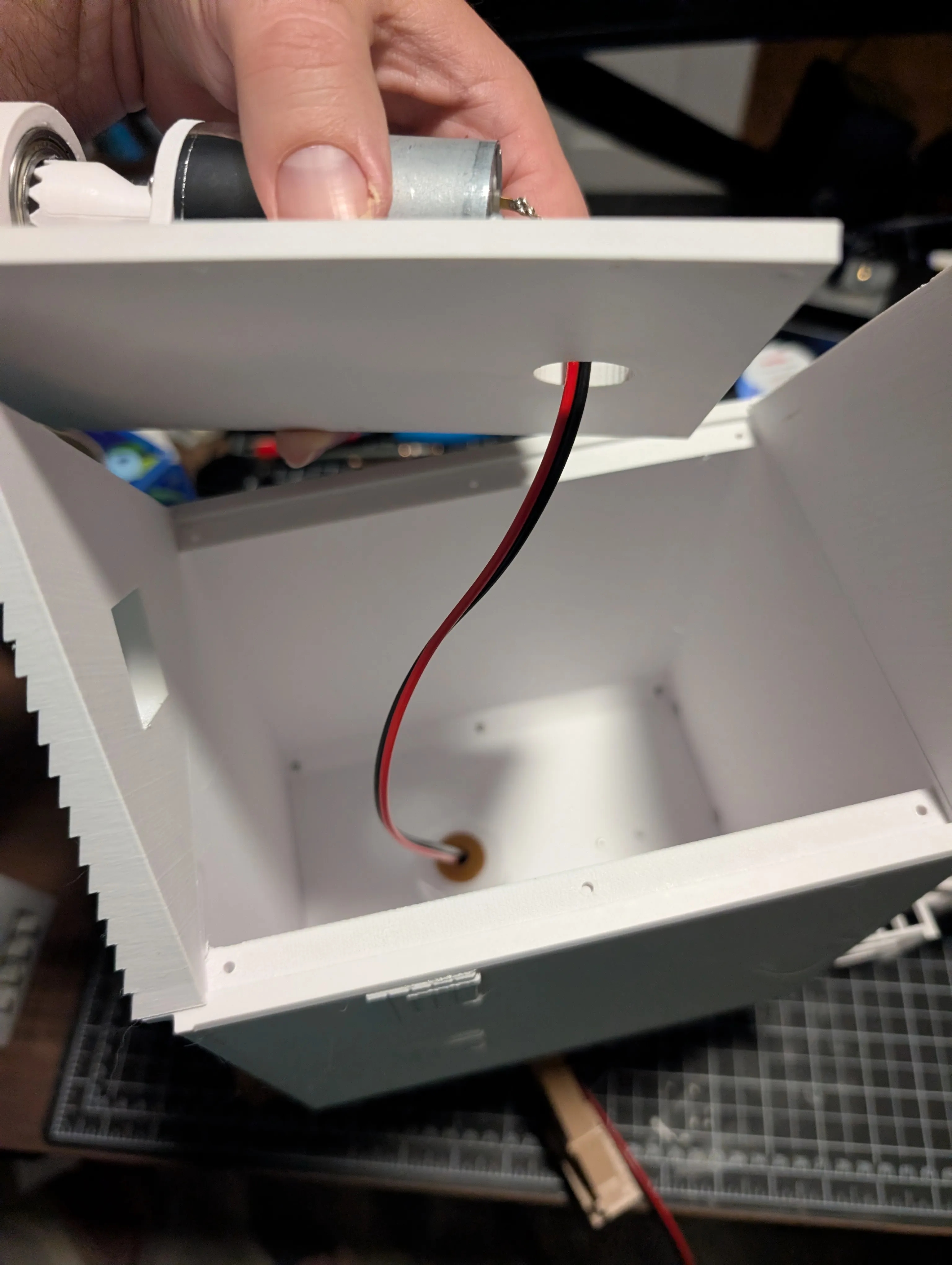
Install the motor mount plate to the body using 6 m3 x 10mm screws. Ensure you route the power wire (if motorized) through the provided hole in the motor mount plate and the central hole of the post.
- Install the blade assembly to the body assembly by slipping it through the front hole and bearing. It should slip without force into place and be pulled in by the clutch magnets.
- Place the roof on, you may glue it once you test everything works if you feel so inclined. And you're done!
License

You shall not share, sub-license, sell, rent, host, transfer, or distribute in any way the digital or 3D printed versions of this object, nor any other derivative work of this object in its digital or physical format (including, but not limited to, publishing derivative works outside the Makerworld platform or hosting on other digital platforms). The objects may not be used without permission in any way whatsoever in which you charge money or collect fees. Subject to the above restrictions, derivative works may be published only within the Makerworld platform, and all such derivative works must be licensed under the same SDFL‑C license, without modification or additional terms. You may download the digital versions of this object, 3D print it, and display images, videos, or usage demonstrations of 3D printed versions of the object on personal social media platforms or Makerworld official channels, provided that no digital versions of the object are shared or distributed.


Comment & Rating (0)