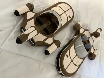
Luke Skywalker's X34 Landspeeder


Print Profile(4)
Description
Taking inspiration from @Festavius Land speeder – X34 from a New Hope, (https://makerworld.com/en/models/1679253-landspeeder-x34#profileId-1778798) I wanted a larger and more detailed version, I want to thank @Festavius especially for the idea using wheels. I know the original X34 doesn’t have wheels, but this makes it appear to be floating, and his design to allow installation was great.
I decided to make most of these single-color plates. The exception to this is the engines, the grill, and the rear instrumentation panels on the back of the speeder. In the profile I do include an option to print the engines and engine panels separately (plate 11) and a single-color grill (plate 13). And, because I had so much time on my hands, I also included a left engine with exposed wiring (you can mirror this if you want to print it as a right engine) on Plate 12.
General note: I printed this in PLA and used PETG as support interface. This makes it very easy to remove any required support material.
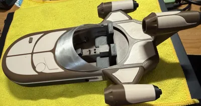
This is a model of the X34 Land Speeder Luke used in A New Hope with Obi-Wan. I think I have made it easy to assemble, but the order of assembly makes it easier. I have made the pieces to fit together snugly. You shouldn’t need glue to initially assemble for most parts. However, after final assembly I would then recommend gluing for handling and display.
First, insert the panels to the top of the speeder. The front and rear panels and the circle piece go all the way through and connect to the bottom of the speeder but just press them flush with the bottom of the top part first. If this causes a problem then you can wait to install the front and rear panels when you connect the top to the bottom section.


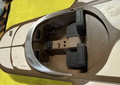
Then you can insert the instrumentation box in the front right panel


Next, you can assemble some of the pieces into the speeder bottom section. A display is mounted onto the center consoled. Make sure the display panel is vertical. You will need to glue the shortest end to the console. The top of the display is larger.

Next you can attach the seats and the steering wheel. The hole for the steering column may not print perfectly round and therefore you may need to round out the hole. The hole should be 1/8 inch or 3.175mm. So, if you have a drill bit use one that is one size smaller than this. This seats should press in. This is a tight tolerance so it may take some pressure. If too tight, carefully use a file to remove a small bit of the wall.


Before you add the top section to the bottom you need to add the left and right engine supports to the speeder bottom. The Top portion of the speeder helps hold these pieces in place.


The top of the engine supports will be above the top surface of the bottom section.
You can now add the top section to the bottom section of the speeder.

And push it down flush, and push the front and read panels to secure.

You can add the engine support panels also.

You can add the 8x8mm connection pegs to the engine support pieces.

Since the top and bottom speeder sections are connected you can add the instrumentation on the dash. Again, make sure you use the small side to fit into the available slots.

You can now turn your attention to the rear engine support pieces. This made up of top and bottom sections. The bottom section also contains an 8x8 peg to go into the speeder bottom section. The peg is redundant if you use glue, but it will help keep it in place if you will wait until the final assembly to use glue.


You can assemble the top[ and bottom rear engine support sections before attaching to the speeder bottom or after. The top also uses an 8x8 peg.

You can now turn your attention to the three engine assemblies. Each engine comprises three sections; fwd, mid and aft. The mid-section has panels. Originally, I planned to make the panels separate but then decided to use the multi-filament capability and that turned out great. Later, I decided I would provide both options. One plate has the three mid sections as a 2-color print and another has them separated. The profile has the plate printed by object instead of layers. This allows printing with very little poop. The mid section requires minimal support for the peg hole.
The two side engines have a single panel and the top engine has a split, or 2-piece panel.
The pictures below show the 2-color printed mid sections along with the fwd and aft sections. If you choose to print single colors, they will look the same. You connect these with more 8x8 pegs.

Since I am retired and have a lot of time on my hands, I decided to make an option to open a panel and have something interesting to see. So, I made a left engine where you can remove the panel to see wiring inside. I just thought this would be fun to do. I will likely just lay it next to speeder and say that is an engine that is in repair. If for some reason you want the right engine then you can just mirror it in your slicer.

.
You can attach the engines now.

Once the engines are installed you can install/glue the rear instrument panels on the very back of the speeder.

Now, you can add the wheels. I know the original X34 didn’t use wheels, but this gives the illusion of floating and I liked the design @Festavius used to install the wheels. They have a wedge cut out so they can snap in and then you can roll them and they do not come out.


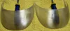
The final step is to add the windshield and glue all the needed pieces. You again have options here; you can print with transparent or white filament if you do not have access to the translucent. If you use translucent (I used Bambu PETG Translucent) then you can use the default value for PETG or you can adjust the setting to try to get it as clear as possible. I have tried this several times with varying success. On my X-Wing fighter I was able to get the thickness small, but it was harder here to make the windshield thin. I did have some minor success, but I am not sure it was worth the effort.

The windshield on the left was printed using default PETG settings and the windshield on the right was printed using the modified settings. The right windshield is more consistent but I leave it to you to determine the worth.
Here are the settings:
- Turn off the any cooling fans: this is under the filament settings.
- Increase flow ratio and nozzle printing temperature. This is also under the filament settings.
- Flow ratio: 1.05 (Bambu used 1.01)
- Print temperature, Nozzle: First Layer 270℃, Other Layers 270℃.
- Set the number of wall loops to 1, remove the top shell and bottom shell, set the infill density to 100%, and change the infill direction to 0° or 90°
- Layer height, set to 0.1mm and line width to 0.5mm.
- Set all speeds to 15mm/s (Bambu used 20mm/s) or a flow rate of 0.1mmx0.5mmx15mm/s = 0.75 mm^3/s
Please let me know what you think and please provide a photo.
Comment & Rating (5)