LeRobot Humanoid - Robot to modify and learn from


Print Profile(1)

Description
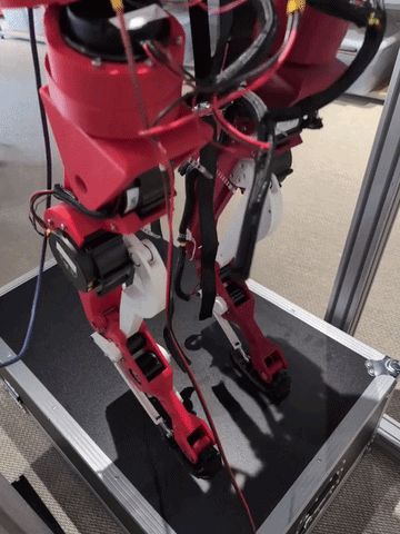
A humanoid you can build, modify, and learn from
Humanoid robots are becoming an increasingly important target for robot learning. They are general-purpose, human-scale platforms, able to interact with the same objects, tools, and environments as we do. But today, experimenting with humanoids remains difficult: the hardware is often expensive, closed, fragile, or hard to reproduce.
This creates a bottleneck for open robot learning. Even when models, datasets, simulators, and training code are released, the physical platforms used to generate data and validate policies often remain inaccessible. Many people can train policies in simulation, but only a small number of labs can close the loop on real humanoid hardware.
LeRobot Humanoid is designed for a specific niche: an open humanoid platform that is affordable enough to reproduce, simple enough to modify, and complete enough to support real robot-learning experiments.
If you are looking for the most advanced humanoid robot, this is not it.
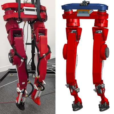
If you are looking for a humanoid you can build, understand, repair, instrument, simulate, and use for learning experiments, this is the robot we are trying to make.
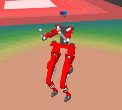
This is why the release includes more than a robot model or a controller. It includes hardware files, assembly documentation, simulation assets, runtime tools, identification pipelines, and training environments. The goal is to make the full humanoid learning loop accessible, from mechanical design to real-world control.
Source (check for updates and detailed infos):
https://github.com/Virgileboat/lerobot-humanoid
https://huggingface.co/blog/VirgileBatto/lerobot-humanoid
BOM:
https://github.com/Virgileboat/lerobot-humanoid-hardware/blob/main/hardware/bom/bom_buy.md
(see also attached file bom_buy.csv)
(scroll down for price overview)
motors
| name | subassembly | qty_subassembly | qty_robot |
|---|---|---|---|
| RobStride O0 | torso | 2 | 2 |
| RobStride O2 | hipz | 1 | 2 |
| RobStride O3 | thigh | 2 | 4 |
| RobStride O5 | shin | 2 | 4 |
torso
| category | name | specification | qty_subassembly | qty_robot |
|---|---|---|---|---|
| electronics_controller | Raspberry Pi 5 | single-board computer | 1 | 1 |
| electronics_imu | IMU | BNO055 or BNO085 | 1 | 1 |
| electronics_canfd_adapter | SAVVYCANFD 2CH CANFD adapter | USB, dual CAN FD, 12 Mbps max | 1 | 1 |
| cable_power | Power cable red | diameter >= 2.5 mm, 5 m | 1 | 1 |
| cable_power | Power cable black | diameter >= 2.5 mm, 5 m | 1 | 1 |
| cable_communication | Communication cable color 1 | 5 m | 1 | 1 |
| cable_communication | Communication cable color 2 | 5 m | 1 | 1 |
| motor | RobStride O0 | actuator | 2 | 2 |
| fastener_screw | M2 screw | M2 x 5 cyl head | 4 | 4 |
| fastener_screw | M2.5 screw | M2.5 x 20 cyl head | 9 | 9 |
| fastener_screw | M3 screw | M3 x 8 cyl head | 12 | 12 |
| fastener_screw | M4 screw | M4 x 20 cyl head | 16 | 16 |
| fastener_screw | M5 screw | M5 x 10 cyl head | 5 | 5 |
Comment: cheaper or better CAN-FD adapters may exist, but this one is currently the only adapter proven in this project to handle the RobStride CAN protocol.
hipx
| category | name | specification | qty_subassembly | qty_robot |
|---|---|---|---|---|
| fastener_screw | M3 screw | M3 x 8 cyl head | 3 | 6 |
| fastener_screw | M4 screw | M4 x 40 cyl head | 6 | 12 |
| fastener_screw | M4 screw | M4 x 45 cyl head | 9 | 18 |
| fastener_screw | M4 screw | M4 x 8 cyl head | 8 | 16 |
hipz
| category | name | specification | qty_subassembly | qty_robot |
|---|---|---|---|---|
| motor | RobStride O2 | actuator | 1 | 2 |
| bearing | Bearing | 35x72x17 | 2 | 4 |
| fastener_screw | M4 screw | M4 x 10 cyl head | 8 | 16 |
| fastener_screw | M4 screw | M4 x 20 cyl head | 8 | 16 |
thigh
| category | name | specification | qty_subassembly | qty_robot |
|---|---|---|---|---|
| motor | RobStride O3 | actuator | 2 | 4 |
| bearing | Bearing | 15x21x4 | 1 | 2 |
| bearing | Bearing | 5x16x5 | 2 | 4 |
| fastener_screw | M2.5 screw | M2.5 x 6 cyl head | 3 | 6 |
| fastener_screw | M4 screw | M4 x 10 cyl head | 4 | 8 |
| fastener_screw | M4 screw | M4 x 23.5 cyl head | 4 | 8 |
| fastener_screw | M4 screw | M4 x 8 cyl head | 10 | 20 |
| fastener_axis | Shoulder screw 07534-05X40 | ISO7379, D1=5, L1=40, B=8, M4, SW=2.5, steel 12.9 | 1 | 2 |
knee_mechanism
| category | name | specification | qty_subassembly | qty_robot |
|---|---|---|---|---|
| bearing | Bearing | 15x21x4 | 2 | 4 |
| fastener_screw | M3 screw | M3 x 12.5 cyl head | 3 | 6 |
| fastener_screw | M4 screw | M4 x 16 cyl head | 8 | 16 |
shin
| category | name | specification | qty_subassembly | qty_robot |
|---|---|---|---|---|
| motor | RobStride O5 | actuator | 2 | 4 |
| bearing | Bearing | 15x21x4 | 4 | 8 |
| fastener_screw | M2.5 screw | M2.5 x 8 cyl head | 3 | 6 |
| fastener_screw | M3 screw | M3 x 17.5 cyl head | 4 | 8 |
| fastener_screw | M3 screw | M3 x 10 cyl head | 24 | 48 |
| fastener_screw | M4 screw | M4 x 18 cyl head | 16 | 32 |
| fastener_screw | M4 screw | M4 x 10 cyl head | 9 | 18 |
| fastener_nut | Nut M4 | M4 nut | 3 | 6 |
| fastener_insert | Heat-set insert M3 | brass threaded insert M3 | 4 | 8 |
ankle_mechanism
| category | name | specification | qty_subassembly | qty_robot |
|---|---|---|---|---|
| fastener_screw | M5 screw | M5 x 15 cyl head | 4 | 8 |
| joint_spherical | Spherical joint 27628-01-05 | Norelem | 4 | 8 |
| fastener_axis | Shoulder screw 07534-05X20 | ISO7379, D1=5, L1=20, B=8, M4, steel 12.9 | 4 | 8 |
ankle
| category | name | specification | qty_subassembly | qty_robot |
|---|---|---|---|---|
| fastener_screw | M2.5 screw | M2.5 x 8 cyl head | 6 | 12 |
| fastener_axis | Shoulder screw 07534-05X40 | ISO7379, D1=5, L1=40, B=8, M4, SW=2.5, steel 12.9 | 1 | 2 |
foot
| category | name | specification | qty_subassembly | qty_robot |
|---|---|---|---|---|
| bearing | Bearing | 5x16x5 | 2 | 4 |
| fastener_screw | M2.5 screw | M2.5 x 8 cyl head | 3 | 6 |
| fastener_nut | Nut M4 | M4 nut | 3 | 6 |
assembly_pins
| category | name | specification | qty_subassembly | qty_robot |
|---|---|---|---|---|
| fastener_pin | Pin d3mm | d3 pin (goupille) | 4 | 8 |
| fastener_pin | Pin d4mm | d4 pin (goupille) | 9 | 18 |
tools
| category | name | specification | qty_subassembly | qty_robot |
|---|---|---|---|---|
| tool | Allen key | 2.5 mm | 1 | 1 |
Price:
The actuators do most of the cost, but you sure need actuators in that price range for a working humanoid robot.
(see detailed list here: https://github.com/Virgileboat/lerobot-humanoid-hardware/tree/main)
| Cost block | Estimate (USD) |
|---|---|
| ankle subtotal | 17.56 |
| ankle_mechanism subtotal | 220.16 |
| assembly_pins subtotal | 13.50 |
| foot subtotal | 8.56 |
| hipx subtotal | 7.84 |
| hipz subtotal | 327.08 |
| knee_mechanism subtotal | 14.58 |
| shin subtotal | 478.10 |
| thigh subtotal | 934.54 |
| tools subtotal | 3.00 |
| torso subtotal | 554.92 |
| BOM-to-buy subtotal (without filament) | 2579.84 |
| PLA+ subtotal (~3.5 kg) | 56.00 |
| Estimated total | 2635.84 |
-------------
Motor Commissioning
- RobStride official product information: https://github.com/RobStride/Product_Information
- RobStride official site (motors): https://www.robstride.com/
The mostors are the key for this project, they are actually cheap compared with other brands.
Commission every motor before mechanical assembly.
Preconditions
- Connect only one motor on the CAN bus during commissioning.
- Adapter: SAVVYCANFD 2CH CANFD adapter (currently the only proven one in this project).
- Linux CAN interface is up (example: can0).
Recommended Command
python commission_motor.py wizard --channel can0
What the Wizard Does
- Detects motor ID and active protocol (CANopen, private, or MIT).
- Switches motor to MIT protocol (with required reboot checkpoints).
- Applies final motor ID according to motor model mapping.
- Reboots and verifies final ID and protocol (MIT).
- Runs motion check: set zero, enable, move to 90 deg for 1 s, then back to 0 deg, then disable motor.
Final ID Map
- RobStride O0: IDs 1, 7
- RobStride O2: IDs 2, 8
- RobStride O3: IDs 3, 4, 9, 10
- RobStride O5: IDs 5, 6, 11, 12
Use one motor at a time and assign one of the allowed IDs for its model.
Batch Policy for This Robot
- Repeat the same process for each motor individually.
- Keep a log table: serial, final_id, final_protocol, commissioning_date.
-----------
Assembly Guide
Assembly order:
- Configure all motors (see commissioning).
- Print all STL parts (all parts are sorted in the mf3.file).
- Build torso first.
- Build upper legs in order: hipx -> hipy (hipz in repo naming) -> thigh (left and right).
- In parallel, build lower legs in order: foot -> ankle -> knee_mechanism -> shin -> ankle_mechanism (left and right).
- Assemble upper and lower leg modules.
- Integrate both legs to torso and run wiring checks.
Common assembly rules:
- For each subassembly, insert bearings first (press or gentle hammer).
- Place motor goupille/pin during the same phase as bearing insertion.
- Exception: in knee_mechanism and ankle, one interface should stay slightly loose but still movable.
- For subassembly goupilles: place them during assembly except on thigh (keep thigh demountable).
- Motor orientation is critical: follow the Onshape assembly orientation relative to each motor connector, otherwise cable length can become insufficient.
- Default thread strategy is direct screw in plastic; use around 5 Nm for non-structural plastic threads.
- For motor threaded holes and structural insert zones, use higher torque appropriate to the thread/material.
- Some fits are intentionally tight; if required, gently ream/drill with a metal bit at low speed.
- Pins are not a standalone assembly stage: install them inside each motor/subassembly during build.
- Tools are prerequisites only (not assemblies).
Leg cabling note:
- Left and right legs use the same sub-cable design and routing logic.
- Cable legend: red = power, green = CAN, blue = CAN + power.
Leg cabling integration order (both legs):
- Prepare three sub-cables using hardware/electronics/cabling/README.md: shin, thigh, hip pass-through.
- Install the shin sub-cable during shin assembly, before final closure.
- Install the thigh sub-cable during thigh assembly, before final tightening.
- Route the hip pass-through sub-cable during hipz integration.
- Join leg cables to torso harness during final leg-to-torso integration.
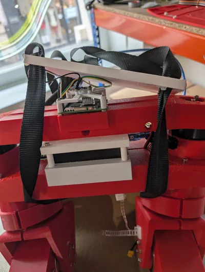
torso

Components:
| Category | Name | Specification | Qty / Subassembly | Qty / Robot |
|---|---|---|---|---|
| electronics_controller | Raspberry Pi 5 | single-board computer | 1 | 1 |
| electronics_imu | IMU | BNO055 or BNO085 | 1 | 1 |
| electronics_canfd_adapter | SAVVYCANFD 2CH CANFD adapter | USB, dual CAN FD, 12 Mbps max | 1 | 1 |
| cable_power | Power cable red | diameter >= 2.5 mm, 5 m | 1 | 1 |
| cable_power | Power cable black | diameter >= 2.5 mm, 5 m | 1 | 1 |
| cable_communication | Communication cable color 1 | 5 m | 1 | 1 |
| cable_communication | Communication cable color 2 | 5 m | 1 | 1 |
| motor | RobStride O0 | actuator | 2 | 2 |
| fastener_screw | M2 screw | M2 x 5 cyl head | 4 | 4 |
| fastener_screw | M2.5 screw | M2.5 x 20 cyl head | 9 | 9 |
| fastener_screw | M3 screw | M3 x 8 cyl head | 12 | 12 |
| fastener_screw | M4 screw | M4 x 20 cyl head | 16 | 16 |
| fastener_screw | M5 screw | M5 x 10 cyl head | 5 | 5 |
STL To Print:
| Name | Quantity |
|---|---|
| torso/torso_can_holder.stl | 1 |
| torso/torso_imu_holder.stl | 1 |
| torso/torso_torso13.stl | 1 |
| torso/torso_torso23.stl | 1 |
| torso/torso_torso33.stl | 1 |
| torso/torso_uper_torso_22.stl | 1 |
| torso/torso_upper_torso_12.stl | 1 |
Comment: cheaper or better CAN-FD adapters may exist, but this one is currently the only adapter proven in this project to handle the RobStride CAN protocol.
Assembly steps:
- Assemble each torso motor on its motor support and screw it.
- Place each motor-support subassembly on top of the bearing stack and screw it.
- Verify both torso motor outputs rotate freely after tightening.
hipx
Components:
| Category | Name | Specification | Qty / Subassembly | Qty / Robot |
|---|---|---|---|---|
| fastener_screw | M3 screw | M3 x 8 cyl head | 3 | 6 |
| fastener_screw | M4 screw | M4 x 40 cyl head | 6 | 12 |
| fastener_screw | M4 screw | M4 x 45 cyl head | 9 | 18 |
| fastener_screw | M4 screw | M4 x 8 cyl head | 8 | 16 |
Comment: the hipx M3 screw line is optional and can be removed without issue.
STL To Print:
| Name | Quantity |
|---|---|
| left_leg/hipx/hipx_2_hipxy_sym.stl | 1 |
| right_leg/hipx/hipx_2_hipxy.stl | 1 |
Assembly steps:
- Start by inserting the hip axis and fixing it to the motor.
- Align hipx parts on the previous subassembly and screw the full assembly.
- Verify hipx motion is free with no hard point.
hipz

Components:
| Category | Name | Specification | Qty / Subassembly | Qty / Robot |
|---|---|---|---|---|
| motor | RobStride O2 | actuator | 1 | 2 |
| bearing | Bearing | 35x72x17 | 2 | 4 |
| fastener_screw | M4 screw | M4 x 10 cyl head | 8 | 16 |
| fastener_screw | M4 screw | M4 x 20 cyl head | 8 | 16 |
STL To Print:
| Name | Quantity |
|---|---|
| left_leg/hipz/hip_z_hipz12_sym.stl | 1 |
| left_leg/hipz/hip_z_hipz22_sym.stl | 1 |
| right_leg/hipz/hip_z_hipz12.stl | 1 |
| right_leg/hipz/hip_z_hipz22.stl | 1 |
Assembly steps:
- Insert hipz bearings.
- Start by inserting the axis and fixing it to the motor (hipz naming in this repo corresponds to the hipy joint).
- Place and screw the motor.
- Route the hip pass-through sub-cable through hipz according to hardware/electronics/cabling/README.md.
- Assemble the bearing to the hipz assembly and verify free motion.
thigh

Components:
| Category | Name | Specification | Qty / Subassembly | Qty / Robot |
|---|---|---|---|---|
| motor | RobStride O3 | actuator | 2 | 4 |
| bearing | Bearing | 15x21x4 | 1 | 2 |
| bearing | Bearing | 5x16x5 | 2 | 4 |
| fastener_screw | M2.5 screw | M2.5 x 6 cyl head | 3 | 6 |
| fastener_screw | M4 screw | M4 x 10 cyl head | 4 | 8 |
| fastener_screw | M4 screw | M4 x 23.5 cyl head | 4 | 8 |
| fastener_screw | M4 screw | M4 x 8 cyl head | 10 | 20 |
| fastener_axis | Shoulder screw 07534-05X40 | ISO7379, D1=5, L1=40, B=8, M4, SW=2.5, steel 12.9 | 1 | 2 |
STL To Print:
| Name | Quantity |
|---|---|
| left_leg/thigh/femur_v2_femur_12_sym_1.stl | 1 |
| left_leg/thigh/femur_v2_femur_22_sym_1.stl | 1 |
| left_leg/thigh/femur_v2_hat_femur_2.stl | 1 |
| right_leg/thigh/femur_v2_femur_12_1.stl | 1 |
| right_leg/thigh/femur_v2_femur_22_1.stl | 1 |
| right_leg/thigh/femur_v2_hat_femur_2.stl | 1 |
Assembly steps:
- Insert the exterior thigh shell (femur_22) into the hipy joint side first (hipz naming in this repo).
- Fix femur_12 to the hipy/hipz side.
- Install and route the thigh sub-cable before final closing (hardware/electronics/cabling/README.md).
- Screw femur_12 and femur_22 together once joint alignment is correct.
- Do not lock thigh with permanent goupilles if you want it demountable.
foot
Components:
| Category | Name | Specification | Qty / Subassembly | Qty / Robot |
|---|---|---|---|---|
| bearing | Bearing | 5x16x5 | 2 | 4 |
| fastener_screw | M2.5 screw | M2.5 x 8 cyl head | 3 | 6 |
| fastener_nut | Nut M4 | M4 nut | 3 | 6 |
STL To Print:
| Name | Quantity |
|---|---|
| left_leg/foot/bearing_spacer14_5_7_3.stl | 1 |
| left_leg/foot/bearing_spacer24_5_7_3.stl | 1 |
| left_leg/foot/bearing_spacer34_5_7_3.stl | 1 |
| left_leg/foot/bearing_spacer44_5_7_3.stl | 1 |
| left_leg/foot/foot_foot.stl | 1 |
| left_leg/foot/foot_hat_small.stl | 1 |
| right_leg/foot/bearing_spacer14_5_7_3.stl | 1 |
| right_leg/foot/bearing_spacer24_5_7_3.stl | 1 |
| right_leg/foot/bearing_spacer34_5_7_3.stl | 1 |
| right_leg/foot/bearing_spacer44_5_7_3.stl | 1 |
| right_leg/foot/foot_foot.stl | 1 |
| right_leg/foot/foot_hat_small.stl | 1 |
Assembly steps:
- Insert foot bearings and pins/goupilles.
- Assemble and screw foot parts.
- Check foot alignment before full tightening.
ankle
Components:
| Category | Name | Specification | Qty / Subassembly | Qty / Robot |
|---|---|---|---|---|
| fastener_screw | M2.5 screw | M2.5 x 8 cyl head | 6 | 12 |
| fastener_axis | Shoulder screw 07534-05X40 | ISO7379, D1=5, L1=40, B=8, M4, SW=2.5, steel 12.9 | 1 | 2 |
STL To Print:
| Name | Quantity |
|---|---|
| left_leg/ankle/ujoint_hat_small_12.stl | 1 |
| left_leg/ankle/ujoint_hat_small_22.stl | 1 |
| left_leg/ankle/ujoint_spacer_12_ujoint.stl | 1 |
| left_leg/ankle/ujoint_spacer_22_ujoint.stl | 1 |
| left_leg/ankle/ujoint_ujoint.stl | 1 |
| right_leg/ankle/ujoint_hat_small_12.stl | 1 |
| right_leg/ankle/ujoint_hat_small_22.stl | 1 |
| right_leg/ankle/ujoint_spacer_12_ujoint.stl | 1 |
| right_leg/ankle/ujoint_spacer_22_ujoint.stl | 1 |
| right_leg/ankle/ujoint_ujoint.stl | 1 |
Assembly steps:
- Assemble U-joint parts and install pins/goupilles.
- Insert the assembled U-joint into shin bearings (bearings are installed in the shin subassembly, not in ankle STL parts).
- Keep one ankle interface slightly loose but still movable.
- Verify free ankle motion after tightening.
knee_mechanism


Components:
| Category | Name | Specification | Qty / Subassembly | Qty / Robot |
|---|---|---|---|---|
| bearing | Bearing | 15x21x4 | 2 | 4 |
| fastener_screw | M3 screw | M3 x 12.5 cyl head | 3 | 6 |
| fastener_screw | M4 screw | M4 x 16 cyl head | 8 | 16 |
STL To Print:
| Name | Quantity |
|---|---|
| left_leg/knee_mechanism/femur_v2_knee_actuation_2.stl | 1 |
| left_leg/knee_mechanism/femur_v2_knee_rod12_sym_1.stl | 1 |
| left_leg/knee_mechanism/femur_v2_knee_rod22_sym_1.stl | 1 |
| right_leg/knee_mechanism/femur_v2_knee_actuation_1.stl | 1 |
| right_leg/knee_mechanism/femur_v2_knee_rod12_1.stl | 1 |
| right_leg/knee_mechanism/femur_v2_knee_rod22_1.stl | 1 |
Assembly steps:
- Pre-assemble the knee mechanism with its motor and rods.
- Keep the knee interface slightly loose but still movable.
- Integrate this knee mechanism inside the shin assembly first.
- Fix the knee motor to the thigh at the end of leg integration.
- Check that knee motion is smooth and not binding.
shin
Components:
| Category | Name | Specification | Qty / Subassembly | Qty / Robot |
|---|---|---|---|---|
| motor | RobStride O5 | actuator | 2 | 4 |
| bearing | Bearing | 15x21x4 | 4 | 8 |
| fastener_screw | M2.5 screw | M2.5 x 8 cyl head | 3 | 6 |
| fastener_screw | M3 screw | M3 x 17.5 cyl head | 4 | 8 |
| fastener_screw | M3 screw | M3 x 10 cyl head | 24 | 48 |
| fastener_screw | M4 screw | M4 x 18 cyl head | 16 | 32 |
| fastener_screw | M4 screw | M4 x 10 cyl head | 9 | 18 |
| fastener_nut | Nut M4 | M4 nut | 3 | 6 |
| fastener_insert | Heat-set insert M3 | brass threaded insert M3 | 4 | 8 |
STL To Print:
| Name | Quantity |
|---|---|
| left_leg/shin/spacer12_5_9_4_5.stl | 1 |
| left_leg/shin/spacer22_5_9_4_5.stl | 1 |
| left_leg/shin/tibias2_hat_big.stl | 1 |
| left_leg/shin/tibias2_shin_spacer_2.stl | 1 |
| left_leg/shin/tibias2_tibias12_sym_4.stl | 1 |
| left_leg/shin/tibias2_tibias22_sym_4.stl | 1 |
| right_leg/shin/spacer12_5_9_4_5.stl | 1 |
| right_leg/shin/spacer22_5_9_4_5.stl | 1 |
| right_leg/shin/tibias2_hat_big.stl | 1 |
| right_leg/shin/tibias2_shin_spacer_2.stl | 1 |
| right_leg/shin/tibias2_tibias12.stl | 1 |
| right_leg/shin/tibias2_tibias22.stl | 1 |
Assembly steps:
- Install M3 inserts first (4 per shin).
- Insert bearings and pins/goupilles.
- Mandatory: place the full knee mechanism (including motor) inside before final shin closure.
- For re-assembly in tight fit conditions: gently shift the bearing with light hammer taps to create spacer clearance, insert spacer, then re-seat bearing.
- Install and route the shin sub-cable before closure (hardware/electronics/cabling/README.md).
- Preferable: place ankle module now (recommended, not mandatory).
- Close and screw shin structure, then verify internal parts still move.
ankle_mechanism
Components:
| Category | Name | Specification | Qty / Subassembly | Qty / Robot |
|---|---|---|---|---|
| fastener_screw | M5 screw | M5 x 15 cyl head | 4 | 8 |
| joint_spherical | Spherical joint 27628-01-05 | Norelem | 4 | 8 |
| fastener_axis | Shoulder screw 07534-05X20 | ISO7379, D1=5, L1=20, B=8, M4, steel 12.9 | 4 | 8 |
STL To Print:
| Name | Quantity |
|---|---|
| left_leg/ankle_mechanism/bearing_spacer14_5_7_3.stl | 1 |
| left_leg/ankle_mechanism/bearing_spacer24_5_7_3.stl | 1 |
| left_leg/ankle_mechanism/bearing_spacer34_5_7_3.stl | 1 |
| left_leg/ankle_mechanism/bearing_spacer44_5_7_3.stl | 1 |
| left_leg/ankle_mechanism/tibias2_rod_long.stl | 1 |
| left_leg/ankle_mechanism/tibias2_rod_small.stl | 1 |
| left_leg/ankle_mechanism/tibias_actuation_ankle_12.stl | 1 |
| left_leg/ankle_mechanism/tibias_actuation_ankle_22.stl | 1 |
| right_leg/ankle_mechanism/bearing_spacer14_5_7_3.stl | 1 |
| right_leg/ankle_mechanism/bearing_spacer24_5_7_3.stl | 1 |
| right_leg/ankle_mechanism/bearing_spacer34_5_7_3.stl | 1 |
| right_leg/ankle_mechanism/bearing_spacer44_5_7_3.stl | 1 |
| right_leg/ankle_mechanism/tibias2_rod_long.stl | 1 |
| right_leg/ankle_mechanism/tibias2_rod_small.stl | 1 |
| right_leg/ankle_mechanism/tibias_actuation_ankle_12.stl | 1 |
| right_leg/ankle_mechanism/tibias_actuation_ankle_22.stl | 1 |
Assembly steps:
- Install spherical joints on rods (2 per rod, 4 per leg, 8 per robot).
- Assemble rods, spacers, and ankle actuation parts, then screw.
- Verify mechanism moves freely through its range.
--------
Code / Training
Now the real work begins, programming and training this robot.
But sadly we hit the maximal post size, so for more visit the GitHub pages.
The project is from May 2026, so its brand new and the work is still progressing.
And yes, we still need the upper half of the robot, all this will follow hopefully.
https://github.com/Virgileboat/lerobot-humanoid
https://github.com/Virgileboat/lerobot-humanoid-runtime
Comment & Rating (3)