KOZOcut ESP32 Cable Cutter


Print Profile(1)
Description
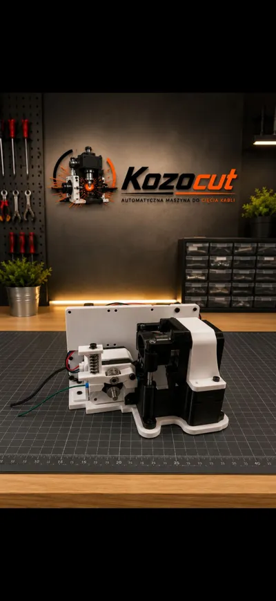
KOZOcut — ESP32-C3 Cable Cutting Machine
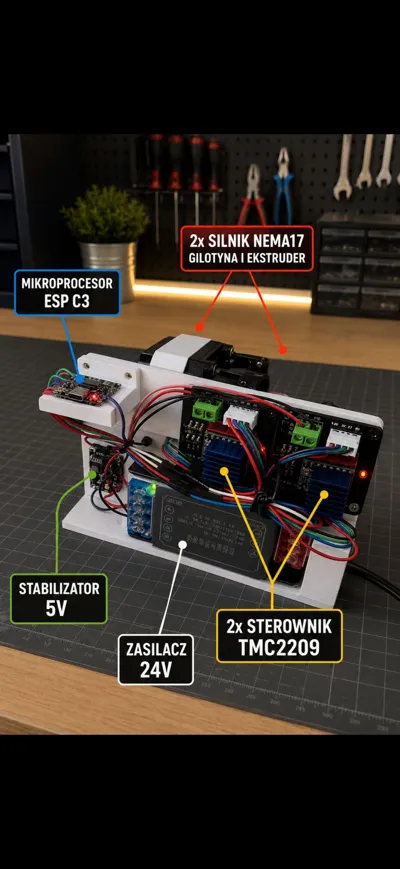
KOZOcut is a compact cable cutting machine based on:
- ESP32-C3 Super Mini
- two NEMA17 stepper motors
- two TMC2209 stepper drivers
The device creates its own Wi-Fi access point called:
KOZOcut
Control panel address:
http://192.168.4.1
Resources
- Firmware repository:
https://github.com/kozomeuszz/KOZOCUT - Control panel:
http://192.168.4.1 Wi-Fi SSID:
KOZOcut
Firmware Features
Main Functions
- automatic cable feeding to a target length (mm)
- production of a selected number of pieces
- single test cut
- manual jog feed
- steps/mm calibration
- adjustable feed and cutting speed
- configurable guillotine movement steps
- configuration stored in ESP32 memory
Required Parts
| Part | Qty | Notes |
|---|---|---|
| ESP32-C3 Super Mini USB-C | 1 | Main controller |
| TMC2209 V2.0 drivers | 2 | Stepper motor drivers |
| NEMA17 17HS4401 motors | 2 | Feeder + guillotine |
| 12V / 24V PSU | 1 | 24V recommended |
| MP1584EN buck converter | 1 | Converts voltage to 5V |
| A4988 / DRV8825 shield | 2 | Optional carrier board |
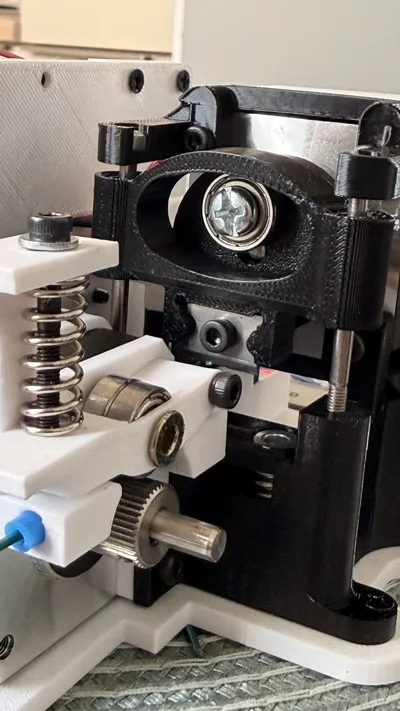
| LM3UU linear bearings | 2 | Linear guide system |
| Extruder springs 1.2x7.5x20 mm | 3 | Feeder pressure |
| 13 mm bearings | 3 | Pressure rollers |
| Blade from UTP/STP stripper | 3 | Guillotine blade |
| M3/M4 screws | as needed | Assembly |
| Rivet nuts + threaded inserts | as needed | Mounting |
| 3D printed parts | project specific | Mechanical structure |
Example Parts Sources
- DRV8825/A4988 expansion board:
https://a.aliexpress.com/_EJtjCLG - Extruder springs 1.2 x 7.5 x 20 mm:
https://a.aliexpress.com/_EzRrIdo - Usongshine NEMA17 17HS4401:
https://a.aliexpress.com/_EuOhsWE - ESP32-C3 Super Mini:
https://a.aliexpress.com/_EHPe6JM - 12V / 24V power supply:
https://a.aliexpress.com/_EuOHUfk - MP1584EN buck converter:
https://a.aliexpress.com/_Ez9iknU - TMC2209 V2.0:
https://a.aliexpress.com/_EGThV0w - LM3UU linear bearings:
https://pl.aliexpress.com/item/1005012350964176.html - M3/M4 countersunk screws:
https://a.aliexpress.com/_Ez9eS9Y - M3/M4 rivet nuts:
https://a.aliexpress.com/_EJ4cOce - Adjustable UTP/STP stripping tool:
https://a.aliexpress.com/_EG4WMGQ - Threaded inserts for plastic:
https://pl.aliexpress.com/item/1005007653131713.html - M3 nuts:
https://pl.aliexpress.com/item/1005009867140248.html
Recommended Power Setup
Recommended Configuration
- 24V DC powers the stepper drivers
- MP1584EN converts 24V → 5V
- 5V powers the ESP32
- ESP32 3.3V powers driver logic (VIO/VDD)
IMPORTANT
⚠️ Never connect 24V directly to the ESP32.
Before connecting the controller:
- set the buck converter to exactly 5.0V
- verify voltage using a multimeter
Driver Enable Logic
Typical TMC2209 enable pin is:
ACTIVE LOW
Meaning:
GPIO4 = LOW -> drivers ENABLED GPIO4 = HIGH -> drivers DISABLED
Wiring Diagram
Power Supply
The system is powered from a 12V or 24V DC power supply.
Recommended configuration:
- 24V powers both TMC2209 stepper drivers
- MP1584EN buck converter reduces voltage from 24V → 5V
- 5V powers the ESP32-C3
- ESP32 3.3V output powers the logic side (VIO/VDD) of both drivers
ESP32-C3 Connections
| ESP32-C3 Pin | Connected To |
|---|---|
| GPIO0 | Feeder driver DIR |
| GPIO1 | Feeder driver STEP |
| GPIO7 | Guillotine driver DIR |
| GPIO3 | Guillotine driver STEP |
| GPIO4 | EN pin on both drivers |
| 3V3 | VIO/VDD on both drivers |
| GND | Common system ground |
| 5V/VBUS | 5V output from buck converter |
Feeder Driver Wiring (TMC2209)
| Driver Pin | Connection |
|---|---|
| VM | 12V/24V from PSU |
| GND | PSU ground |
| VIO/VDD | ESP32 3.3V |
| STEP | GPIO1 |
| DIR | GPIO0 |
| EN | GPIO4 |
| Motor outputs | Feeder NEMA17 motor |
Guillotine Driver Wiring (TMC2209)
| Driver Pin | Connection |
|---|---|
| VM | 12V/24V from PSU |
| GND | PSU ground |
| VIO/VDD | ESP32 3.3V |
| STEP | GPIO3 |
| DIR | GPIO7 |
| EN | GPIO4 |
| Motor outputs | Guillotine NEMA17 motor |
Common Ground Requirement
All grounds MUST be connected together:
- power supply GND
- buck converter GND
- ESP32 GND
- both driver GND pins
Without common ground the system may behave unpredictably or drivers may not respond correctly.
Driver Enable Logic
EN on typical TMC2209 drivers is:
ACTIVE LOW
Meaning:
GPIO4 = LOW → drivers ENABLED GPIO4 = HIGH → drivers DISABLED
Common Ground Requirement
All grounds MUST be connected together:
- PSU ground
- buck converter ground
- ESP32 ground
- both driver grounds
3D Printed Parts
Recommended mechanical split:
- main frame
- feeder motor mount
- guillotine motor mount
- cable guide
- pressure mechanism
- electronics holder
- blade cover
Mechanical Notes
Before connecting motors:
✅ check smooth movement manually
✅ verify blade alignment
✅ verify bearing pressure
If mechanics bind or jam:
- motors may skip steps
- drivers may overheat
- cuts may become inaccurate
Calibration
Default firmware value:
44.0 steps/mm
Calibration Procedure
1. Feed known length
Example:
100 mm
2. Measure actual length
Example:
96.5 mm
3. Calculate new value
new_steps_per_mm = old_steps_per_mm × (target_length / measured_length)
Example:
44.0 × (100 / 96.5) = 45.60
Build & Upload
Project uses PlatformIO.
Build
pio run
Upload
pio run -t upload
Serial Monitor
pio device monitor
Default PlatformIO Port
monitor_port = /dev/cu.usbmodem1101 upload_port = /dev/cu.usbmodem1101
If your board appears on another port:
- change the values manually
- or remove them entirely for auto-detection
First Startup Procedure
Initial Setup
- verify wiring with motors disconnected
- set buck converter to 5V
- upload firmware
- connect motors and drivers
- enable motor power
- connect to Wi-Fi network:
KOZOcut
- open:
http://192.168.4.1
- perform:
- jog test
- single cut test
- steps/mm calibration
Safety Notes
⚠️ 230V AC is dangerous.
Always:
- disconnect power before wiring
- insulate terminals
- use blade covers
- never run the cutter exposed
Additional Notes
The firmware assumes every cut uses a fixed number of guillotine steps:
guillotineStepsPerCut = 1600
If blade position drifts over time:
- add a limit switch
- or implement mechanical homing
Firmware Repository
GitHub:
https://github.com/kozomeuszz/KOZOCUT
Repository contains:
- complete PlatformIO project
- ESP32-C3 firmware source
- web control panel
- motor control logic
- calibration system
- configuration storage
Comment & Rating (2)