
Parametric Barbed T Hose Adapter - Metric Version
Print Profile(1)
Description
Boost Me (for free)
If this parametric T hose adapter helped you solve a real hose routing or workshop connection problem, a boost would be greatly appreciated.
It helps support more practical, functional and customizable maker tools.
Description
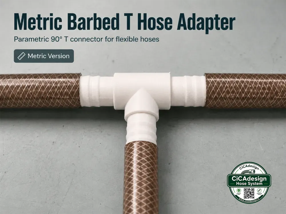
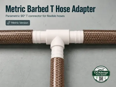
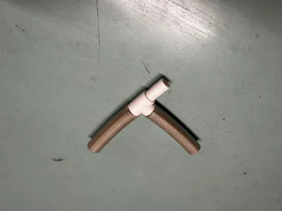
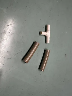
This is a parametric barbed T hose adapter designed for flexible rubber, silicone and soft PVC tubes.
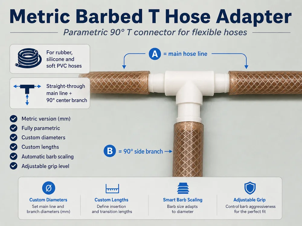
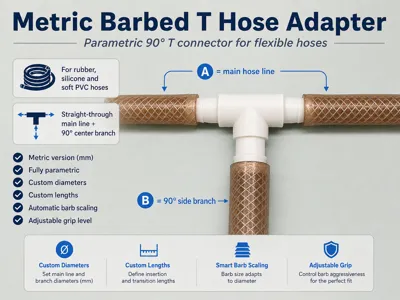
The model creates a T-shaped hose connector where:
- A is the main straight-through hose line;
- B is the 90° side branch coming out from the center of A.
This is the metric version of the model. All editable dimensions are expressed in millimeters.
The design can be customized directly in Fusion 360 / MakerWorld Customizer by changing the main parameters, allowing users to create different metric T hose adapters, equal T connectors and reduced T connectors.
It is intended for light-duty workshop, DIY, maker, hobby and utility use, such as:
flexible rubber hose routing
silicone tube connections
soft PVC tube adapters
low-stress drain or vent lines
custom workshop hoses
prototype hose routing
maker projects and experimental setups
non-critical fluid or air routing
The barbs are automatically scaled from the hose diameter, wall thickness and grip level, so the user does not need to manually adjust many technical values.
Part of the CiCadesign Parametric Hose Connector System
This model is part of a growing set of functional, customizable hose and tube adapters designed for workshop, DIY, prototyping, light-duty routing and experimental setups.
Other connector variants are available on my profile, including straight, T, Y, barbed, smooth sleeve, Metric and Inch Preset versions.
Important Geometry Note
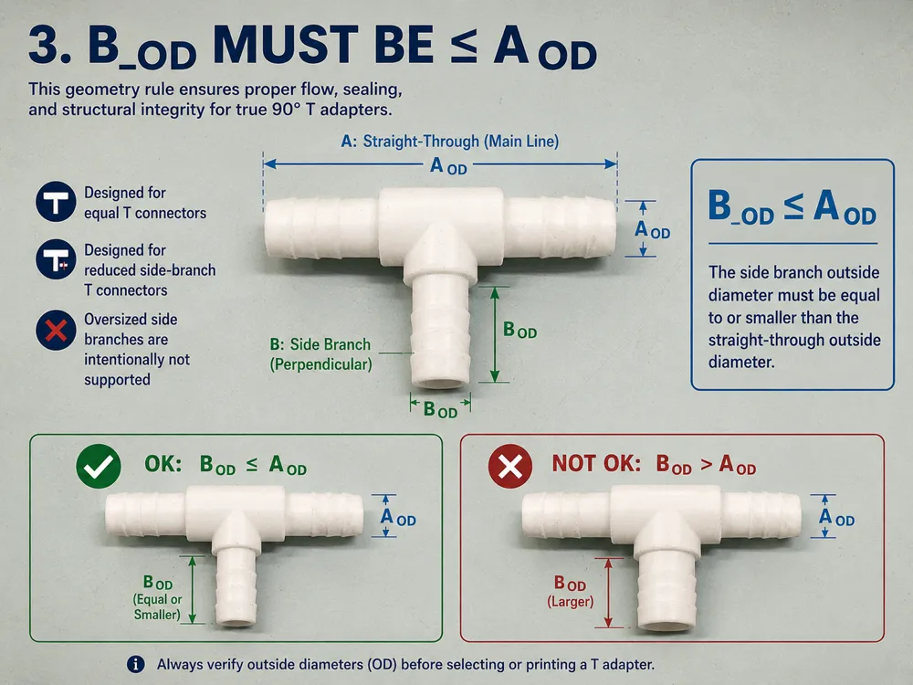
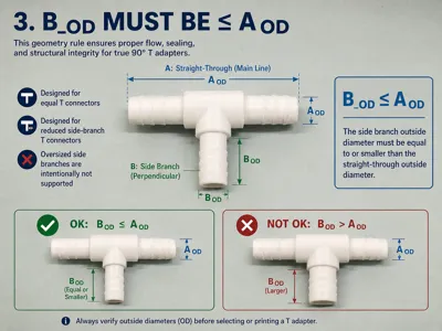
In this metric T adapter, B_OD must be smaller than or equal to A_OD.
The main A hose line is the straight-through tube, while B is the 90° side branch coming out from the center of A.
This model is designed for:
equal T connectors, where A_OD = B_OD;
reduced T connectors, where B_OD < A_OD.
B_OD values larger than A_OD are intentionally not recommended and should be avoided, because they can weaken the central T intersection, create an unbalanced geometry and make the printed fitting less reliable.
For this reason, the parametric setup is intended to limit B_OD to values equal to or smaller than A_OD.
Main Features
Fully parametric T hose adapter
Metric version
All dimensions in millimeters
Straight-through A hose line
90° centered B branch
Custom A and B diameters
Custom A and B insertion lengths
Automatic barb scaling
Adjustable grip level
Internal through-hole
Reinforced central T body
Suitable for equal T connectors and reduced T connectors
Designed for flexible hoses
Practical workshop-oriented design
Printable on standard FDM printers
Designed to be printed strong, with many walls / almost solid profiles
Recommended Parameters
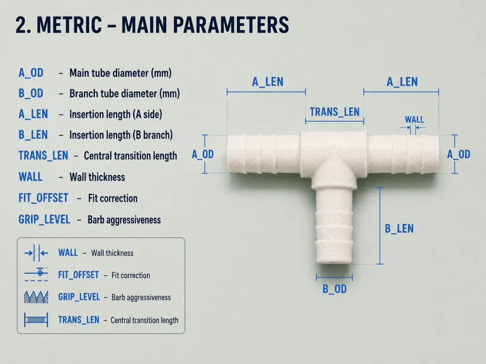
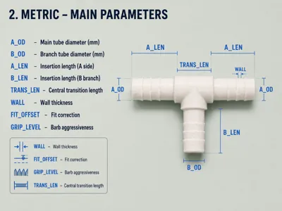
The most important editable parameters are:
| Parameter | Description |
|---|---|
| A_OD | Outside diameter of the main straight-through A barb section |
| B_OD | Outside diameter of the 90° side B barb section. Must be smaller than or equal to A_OD |
| A_LEN | Insertion length of each side of the main A tube |
| B_LEN | Insertion length of the side B tube |
| TRANS_LEN | Reinforced central transition length around the T intersection |
| WALL | Wall thickness |
| FIT_OFFSET | Diameter correction for tighter or looser hose fit |
| GRIP_LEVEL | Barb aggressiveness / holding strength |
Parameter Meaning
A_OD
Controls the outside diameter of the barbed section on the main straight-through hose line.
Use this value according to the internal diameter of the flexible hose used on the main A line.
Example:
| Hose ID | Suggested A_OD |
|---|---|
| 8 mm hose | 8 mm |
| 10 mm hose | 10 mm |
| 12 mm hose | 12 mm |
| 16 mm hose | 16 mm |
| 20 mm hose | 20 mm |
| 25 mm hose | 25 mm |
| 32 mm hose | 32 mm |
B_OD
Controls the outside diameter of the 90° side branch.
B_OD can be the same as A_OD for an equal T connector, or smaller than A_OD for a reduced T connector.
B_OD must not be larger than A_OD.
Example:
| Main A hose | Side B hose | Use |
|---|---|---|
| 8 mm | 8 mm | Equal small T connector |
| 10 mm | 10 mm | Equal small T connector |
| 12 mm | 12 mm | General equal T connector |
| 16 mm | 12 mm | Reduced side branch |
| 20 mm | 16 mm | Workshop hose branch |
| 25 mm | 20 mm | Larger reduced T connector |
| 32 mm | 25 mm | Large light-duty branch adapter |
A_LEN
Controls the insertion length on both straight sides of the main A tube.
In this model, A is continuous, so A_LEN is applied symmetrically to both sides of the T connector.
Longer A_LEN gives:
better hose retention
more barb contact area
stronger mechanical hold
more space for multiple barbs
Shorter A_LEN gives:
more compact adapter
faster print
less material use
Recommended starting values:
| Diameter | Suggested A_LEN |
|---|---|
| 8–10 mm | 22–28 mm |
| 12–16 mm | 28–35 mm |
| 20–25 mm | 35–45 mm |
| 32 mm | 45–55 mm |
B_LEN
Controls the insertion length of the 90° branch.
Recommended values are similar to A_LEN, but B_LEN can be slightly shorter if compactness is important.
| Diameter | Suggested B_LEN |
|---|---|
| 8–10 mm | 22–28 mm |
| 12–16 mm | 28–35 mm |
| 20–25 mm | 35–45 mm |
| 32 mm | 45–55 mm |
TRANS_LEN
Controls the reinforced central transition length around the T intersection.
This is the structural area where the main A tube and the side B branch meet.
A larger TRANS_LEN creates a stronger and smoother central body, especially on larger fittings or when using thicker walls.
Recommended values:
| Adapter size | Suggested TRANS_LEN |
|---|---|
| Small fittings | 8–12 mm |
| Medium fittings | 12–18 mm |
| Larger fittings | 18–25 mm |
For stronger parts, especially with larger diameters, increase TRANS_LEN slightly.
WALL
Controls the wall thickness of the adapter.
Recommended values:
| Use | Suggested WALL |
|---|---|
| Small light-duty fittings | 1.4–1.8 mm |
| General use | 1.8–2.4 mm |
| Larger fittings | 2.4–3.2 mm |
| Stronger workshop use | 3.0 mm or more |
For small diameters, avoid using too large a wall thickness because the internal hole may become too restricted.
For larger diameters, increasing WALL improves strength around the T intersection.
FIT_OFFSET
Controls the final barb diameter correction.
Use it to compensate for hose flexibility, material shrinkage and printer tolerance.
| FIT_OFFSET | Effect |
|---|---|
| -0.2 mm | Slightly looser fit |
| 0 mm | Nominal size |
| +0.2 mm | Tighter fit |
| +0.4 mm | Stronger interference fit |
For flexible rubber hoses, a small positive value can improve grip.
For harder hoses, start with 0 mm or a small negative value.
GRIP_LEVEL
Controls how aggressive the barb geometry is.
| Grip Level | Use |
|---|---|
| 0 | Very soft grip / easy removal |
| 1 | Light grip |
| 2 | Standard grip |
| 3 | Stronger grip, recommended with hose clamp |
Recommended starting value:
GRIP_LEVEL = 2
Use GRIP_LEVEL = 3 only when the hose is soft enough or when using a hose clamp.
Example Metric Presets
For this model, the side branch B is limited to equal or smaller diameters than the main A line.
This means the adapter is intended for:
A × A × A equal T connectors
A × A × B reduced T connectors where B ≤ A
It is not intended for T connectors where the side branch is larger than the main hose line.
| Preset | A main tube | B side tube | Use |
|---|---|---|---|
| 8 × 8 × 8 mm | 8 mm | 8 mm | Small silicone hose T |
| 10 × 10 × 10 mm | 10 mm | 10 mm | Small rubber hose T |
| 12 × 12 × 12 mm | 12 mm | 12 mm | General equal T connector |
| 16 × 16 × 16 mm | 16 mm | 16 mm | Medium equal T connector |
| 16 × 16 × 12 mm | 16 mm | 12 mm | Reduced side branch |
| 20 × 20 × 16 mm | 20 mm | 16 mm | Workshop hose branch |
| 25 × 25 × 20 mm | 25 mm | 20 mm | Larger flexible hose branch |
| 32 × 32 × 25 mm | 32 mm | 25 mm | Large light-duty adapter |
Naming logic:
A × A × B
Example:
20 × 20 × 16 mm means:
- 20 mm main tube on the left;
- 20 mm main tube on the right;
- 16 mm 90° side branch.
Printing Recommendations
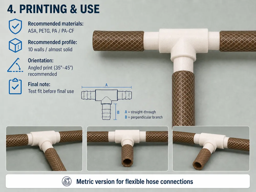
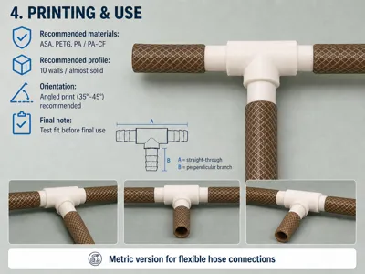
Recommended materials:
| Material | Recommendation |
|---|---|
| ASA | Best choice for stronger and more heat-resistant parts |
| PETG | Good general-purpose option |
| PA / PA-CF | Excellent if available, especially for demanding workshop use |
| PLA | Only for indoor, light-duty, non-warm applications |
Suggested print settings:
| Setting | Recommendation |
|---|---|
| Layer height | 0.16–0.24 mm |
| Walls/perimeters | 6–10 |
| Recommended profile | 10 walls for an almost solid part |
| Top/bottom layers | 5–7 |
| Infill | 40–100% |
| Material | ASA or PETG recommended |
| Supports | May be required depending on orientation |
| Brim | Recommended for ASA |
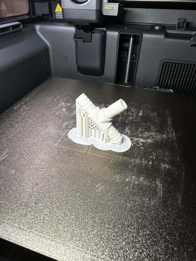
| Orientation | Angled or optimized for branch strength |
For this type of small functional fitting, I recommend using many walls rather than relying only on infill.
The print profile can use 10 walls/perimeters to make the part almost solid, improving mechanical strength, hose clamp resistance and durability around the central T intersection.
This is especially useful because the part is small, hollow and mechanically stressed by hose insertion, hose removal and possible clamp pressure.
Print Orientation Notes
Because this is a T-shaped fitting, print orientation is more important than for a straight adapter.
For best strength, avoid orienting the part in a way that makes the B branch weak along layer lines.
Recommended options:
Option 1 — Angled print
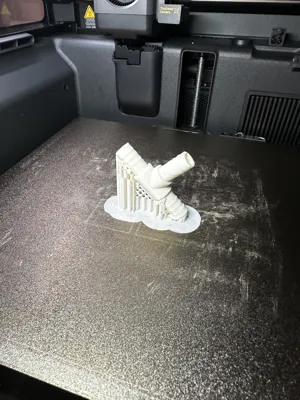
Printing the adapter tilted around 35–45° can improve strength around the T intersection and reduce the risk of snapping along layer lines.
This is usually the best general-purpose orientation.
Option 2 — A tube horizontal
This can give a cleaner A line, but the B branch may need supports and the T intersection may be more sensitive to layer adhesion.
Option 3 — B branch vertical
This can improve the side branch surface quality, but the straight A tube may need more support depending on geometry.
For stronger parts:
use ASA, PETG, PA or PA-CF;
use many walls/perimeters, preferably up to 10 for an almost solid part;
increase wall thickness for larger fittings;
avoid low infill with thin fittings;
print hotter within the safe range of your material to improve layer bonding;
use a brim when printing ASA;
test the part before real use.
Suggested Use
Measure the internal diameter of the flexible hoses.
Set:
- A_OD according to the main hose internal diameter;
- B_OD according to the side branch hose internal diameter.
Make sure that:
B_OD ≤ A_OD
Then:
- Use GRIP_LEVEL = 2 as a starting point.
- Use FIT_OFFSET = 0 mm for the first test.
- Print a small test version if needed.
- Increase FIT_OFFSET slightly if the hose is too loose.
- Reduce FIT_OFFSET if the hose is too tight.
- Use hose clamps where needed.
- Test carefully before real use.
Important Safety Notes
This model is intended for non-critical, light-duty and hobby use only.
Do not use this printed part for:
high-pressure systems;
compressed air safety-critical systems;
fuel lines;
brake lines;
hydraulic systems;
drinking water systems;
food-contact use;
medical use;
hot fluids;
toxic or hazardous chemicals;
any application where failure could cause injury, damage or leakage of dangerous substances.
3D printed parts can fail depending on:
material;
print orientation;
layer adhesion;
temperature;
chemical exposure;
hose stiffness;
clamp pressure;
mechanical stress;
UV exposure;
long-term creep.
Always test the part carefully before use.
Use hose clamps where needed.
The designer is not responsible for misuse or damage caused by improper application.
Print Profile Note
This is a fully parametric Fusion 360 / MakerWorld Customizer model.
The project is intended to let users generate their own custom hose fitting size rather than relying only on fixed-size print profiles.
The model has been personally tested on a Qidi Plus 4, and I now also use a Bambu Lab H2D.
For the provided profile, I recommend using 10 walls/perimeters to obtain an almost solid functional part.
Users should still slice the generated version according to their printer, material, hose dimensions and intended use.
Verified community print profiles are welcome and appreciated.
Customizer Note
The parametric version is intended to be edited from Fusion 360 / MakerWorld Customizer — PC version.
Bambu Handy is mainly intended for direct printing from ready print profiles and may not provide full access to editable source geometry.
License

You shall not share, sub-license, sell, rent, host, transfer, or distribute in any way the digital or 3D printed versions of this object, nor any other derivative work of this object in its digital or physical format (including - but not limited to - remixes of this object, and hosting on other digital platforms). The objects may not be used without permission in any way whatsoever in which you charge money, or collect fees.


Comment & Rating (1)