Jiashikai 48V (16 series) or 24V (8 series 2 parallel) with protection board compartment


Print Profile(2)

Description
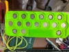
2026-07-13 Added two photos
Printed a complete cover, photos uploaded
Since it was printed for a friend, I didn't get photos after assembly
---------------------------------------------------------------------------------------------
2026-06-27 Updates
Adjustments and additions include:
1 Two separate electrode protection plates
2 Standard side guard plates
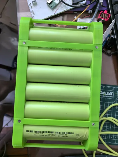
3 Integrated battery cover (optional)
4 Integrated universal protection board fixing adapter plate (too time-consuming, better to use a full plate to drill your own holes or self-tapping screws)
5 A board requiring self-tapping screws for fixing has been released in print profile 2
---------------------------------------------------------------------------------------------
I Overview
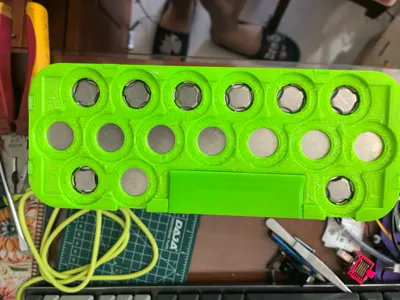
This model is a dedicated battery holder for JiaShikai 32140 cells, specifically designed for assembling 32140 specification lithium battery modules. Its structure is adapted for cell installation and fixing, nickel strip welding routing, and integrated protection board assembly. The overall structure is stable, with high assembly tolerance, capable of meeting the assembly and usage needs of two common lithium battery module specifications, suitable for energy storage and power equipment battery pack construction scenarios
II Applicable Specifications
This holder supports dual-specification battery module assembly and is compatible with two mainstream wiring schemes, offering extreme adaptability:
- 48V 16S 32140 lithium battery pack assembly
- 24V 8S2P 32140 lithium battery pack assembly
III Core Structural Design
1 Nickel Strip Routing Guide Slot Design
The holder features dedicated nickel strip connection guide slots, with slot dimensions compatible with standard battery connection nickel strip specifications, ensuring neat routing and precise positioning. This effectively secures the nickel strip routing path, preventing misalignment, overlap, bending, or damage to the nickel strips, while also standardizing the module wiring layout, reducing risks of short circuits and poor contact, and enhancing the overall assembly integrity and electrical safety of the battery pack
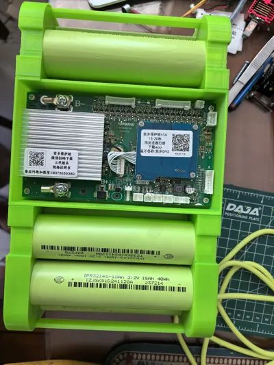
2 Dedicated Installation Position for Balancing Protection Board
The model provides ample space for the battery balancing protection board, with slot and restraint structures designed to fit standard protection board dimensions. No additional drilling, sanding, or modification is required; the balancing protection board can be directly fitted and secured, ensuring flat and firm installation. This facilitates normal functioning of subsequent battery balancing, overcharge, and over-discharge protection features, while also simplifying the overall module assembly process
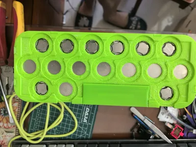
3 Cell Fixing Structure
The cell slots in the holder feature a precise tolerance design, compatible with 32140 cylindrical cell dimensions, providing a snug fit for secure fixing of individual cells, preventing looseness, displacement, or collision. The cell arrangement maintains reasonable spacing, providing natural heat dissipation gaps to prevent heat buildup during battery pack operation, thus ensuring long-term stable operation of the module
IV 3D Printing Recommended Parameters
To ensure the structural strength, dimensional accuracy, and long-term durability of the holder, the following printing parameters are recommended for conventional FDM 3D printers:
- Recommended filament: PETG/ABS (high toughness, high temperature resistance, not easily deformable, suitable for long-term use in battery module scenarios)
- Layer height: 0.2mm (balancing printing accuracy and efficiency)
- Wall thickness: 2 walls or more, to ensure structural rigidity
- Infill density: 15%-20% (balancing strength and lightweight design, no need for high infill redundancy)
- Supports: Only add as needed for complex slots, to avoid excess support residue affecting assembly
V Assembly Instructions
1 After printing, clean burrs and support residue from the model, ensure that the cell slots, nickel strip guide slots, and protection board mounting positions are free from blockages or deformation
2 Arrange the 32140 cells in order according to 48V 16S and 24V 8S2P specifications, ensuring cells are fully inserted into the restraint slots
3 Lay out and arrange the connecting nickel strips along the dedicated guide slots, then complete the cell series and parallel welding
4 Insert the balancing protection board into the reserved installation space, secure it in place, and then complete the overall module wiring assembly
License
You shall not share, sub-license, sell, rent, host, transfer, or distribute in any way the digital or 3D printed versions of this object, nor any other derivative work of this object in its digital or physical format (including - but not limited to - remixes of this object, and hosting on other digital platforms). The objects may not be used without permission in any way whatsoever in which you charge money, or collect fees.
Comment & Rating (0)