Alien Jellyfish Wind Spinner v2


Print Profile(5)


Description
Important Update
Please make sure to download the latest Version 2.2 print profile.
Version 2.2 replaces the threaded assembly system with a much simpler and significantly stronger plug-in connector design. The new connector uses a hexagonal shape that simply presses together, making assembly much faster and more reliable.
The tolerances have been tuned to provide a secure friction fit, so glue should not be necessary under normal conditions, although you are of course welcome to use it if you prefer.
An additional advantage of the new connector system is that the model will spin correctly regardless of which of the possible orientations the connector is inserted in. However, if you are assembling a full ring-shaped configuration, make sure all connectors are aligned consistently throughout the assembly.
Alien Jellyfish Wind Spinner -- Version 2
First of all, a huge thank you for all the feedback, comments, and testing from Version 1. It genuinely helped shape and improve this updated version. Many of the key changes in Version 2 come directly from issues and suggestions reported by users, especially regarding friction, assembly difficulty, and durability.
Printing: Overview
This overview accounts for all versions of the wind spinner 2.
Overview – Version 2 Improvements
This is Version 2 of the Alien Jellyfish Wind Spinner. The most notable changes, in order of importance, are:
- Integrated print-in-place ball bearings in the rotational joints
- Replaced previous connector system with threaded connectors for easier and more reliable assembly
- Added new stand options and improved mounting capabilities
- Optimized aerodynamics of the cup geometry for improved wind performance
- Strengthened and refined connectors between spinning joints
- Reinforced structural beams between wind cups for improved rigidity
- Additional minor adjustments to reduce friction and improve overall durability
Design Changes & Engineering Notes
1. Bearing Integration
The added bearings were actually something I originally experimented with during the development of Version 1, but at the time I abandoned the idea because of the added complexity, increased development time, longer print times, and higher filament cost.
However, the friction in Version 1 ultimately proved to be the biggest limiting factor preventing the joints from spinning properly, so I revisited the earlier bearing prototypes and refined the design further.
Through extensive prototyping, I found that a cylindrical 45° zig-zag pattern provided the most stable solution for a print-in-place bearing system. The 45° overhang angle was also the practical limit of what I found could still be printed reliably without support. The zig-zag pattern repeats throughout the geometry wherever space allows.
I also performed extensive tolerance testing and found that an offset of 0.3 mm provided the tightest possible clearance while still allowing the bearings to roll smoothly. Long cylindrical shapes tended to jam or twist even at relatively loose tolerances, but the zig-zag pattern helps counteract this effect by acting almost like a guiding rail, allowing the cylinders to move more smoothly through the bearing assembly.
This redesign did increase the complexity, print time, filament usage, and overall size of the segments. However, it proved to be well worth the tradeoff, as it dramatically reduced friction in the spinning joints and ultimately allowed the entire sculpture to rotate in much lower wind speeds compared to Version 1, which required very strong winds to function properly.

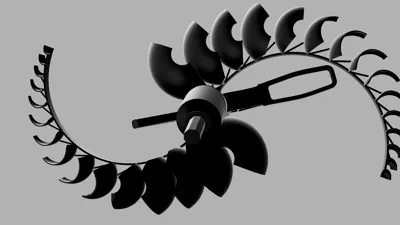
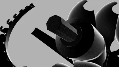
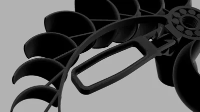
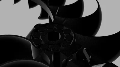
This picture shows a section analysis in Fusion 360 of the integrated ball bearing system inside the segment joint.
2. Threaded Assembly System (Version 2.0 and Version 2.1)
For Version 2, I decided to abandon the assembly system used in Version 1 in favor of a threaded connection system. At a certain point, there is no reason to reinvent the wheel although implementing a reliable threaded solution for 3D printing ended up being easier said than done.
Fortunately, I already had some experience designing printable threads, but I still performed extensive testing to find the optimal tolerances for both easy assembly and a secure fit. Overall, I feel that threaded connections are much more intuitive and easier for most people to understand during assembly compared to the previous locking mechanism.
One additional challenge was ensuring that each segment would line up perfectly once the threads were fully tightened. This also required several prototype iterations before achieving consistent alignment between connected segments.
As with most design changes, there are still some drawbacks to the new system. Firstly, if the threaded connections are not fully tightened, they can actually be more fragile than the assembly system used in Version 1. Secondly, assembly still requires rotating the segments multiple times until the entire thread is fully seated and tightened, compared to Version 1 where the segments only needed a single twist-lock motion.
However, despite these drawbacks, the new threaded system proved to be well worth it. It is significantly more intuitive to assemble, aligns the segments more consistently, and provides a much tighter connection overall, giving the entire sculpture improved rigidity and stability.


These pictures show the male and female threaded connectors, both featuring a pointed tip to help guide and center the connection during assembly.
Threaded Assembly video:
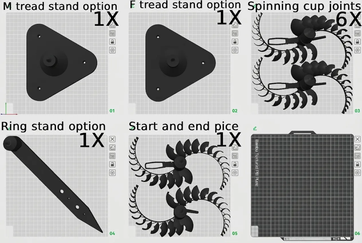
3. Stand & Mounting System
The mounting system in Version 1 was more of an afterthought and left a lot to be desired. It lacked any real mounting capabilities and was essentially just a spike designed to stick into the ground.
For Version 2, I wanted to create a more modular system with multiple mounting options. The original spike stand has been redesigned to be more ergonomic and now includes mounting holes for screws or bolts. I also designed an alternative stand option featuring additional mounting points for more flexible installation possibilities.
For assembly, always begin from the stand and build the rest of the sculpture outward from there.


These images show the different stand configurations, mounting options, and assembly variations available in Version 2, including a 90°, 180°, 270° and 360° option.
4. Aerodynamic Cup Optimization
I also made several changes to the cup geometry on the rotating arms of the spinning joints. The entire model was scaled up slightly so that two segments fit perfectly on the build plate, while also allowing additional room to improve the aerodynamic surfaces.
Two larger additional cups were added for improved wind capture, and the shape of all the cups was refined for slightly better aerodynamic efficiency overall.
These changes did increase the filament usage slightly, but the larger size and optimized cup geometry significantly improved the wind-catching performance and overall rotational efficiency of the sculpture.


These photos compare the cup geometry of Version 2 (left) with Version 1 (right).
5. Structural Reinforcements
Version 1 had some issues with rigidity and overall structural integrity, especially under stronger wind loads and during assembly.
To improve this, I added triangular reinforcement structures between the cups and support arms. These reinforcements help maintain the optimal position and angle of the cups, prevent unwanted bending or deformation, and reduce the risk of the segments interfering with one another during rotation.
The added rigidity also improves aerodynamic efficiency by helping the cups maintain their intended orientation while spinning.


These images show the triangular reinforcement structures in greater detail.
6. Friction, Durability & Other Improvements
I added several smaller improvements focused on reducing friction and increasing durability.
The top of the segments where the male thread is located has been slightly chamfered to prevent interference and rubbing against the ball bearings during rotation. I also changed the slicing settings for the spinning segments to a random seam position to better distribute surface irregularities caused by layer seams.
In addition, I slightly redesigned the connector system between the spinning parts of the segments. The protruding rod was thickened, and the receiving arm was optimized to better guide and secure the connection while minimizing friction.
As in Version 1, I also reinforced potential weak points in the model by adding internal geometry that forces the slicer to generate additional wall layers in specific stress areas.
After seeing a user report a broken connector that could not be removed, I also added a hidden emergency removal slit that allows the part to be unscrewed if it fails in that exact location. This feature is only visible if the part breaks at that specific point.
Finally, I added a few subtle contour changes and minor cosmetic refinements to make the overall model cleaner and more visually appealing.


Notes on Version 2
- The model is slightly larger than Version 1
- Print time is increased
- Material usage is higher, but still well under 1 kg of filament (for a full assembly with all mounts)
- Designed for improved reliability, smoother motion, and easier assembly
Final Notes
Version 2 is a direct response to all the feedback from Version 1, with a strong focus on reducing friction, improving durability, and making assembly more intuitive and reliable.
Thank you to everyone who tested, commented, and shared feedback it genuinely helped shape this improved design.
As always, I would really love to see your prints, makes, and any feedback or suggestions for further improvements.
Support & Additional Reading
If you would like to support my work, you can:
- Boost the model
- Purchase filament through the BOM links
- Or join the commercial/support membership tier on my profile
Support genuinely helps fund future prototypes, filament, testing, and development for projects like this.
If you are interested in the full development story, you can also check out:
- The original Version 1 upload: https://makerworld.com/en/models/2770484-alien-jellyfish-wind-spinner#profileId-3077284
The development article/community post: https://makerworld.com/en/community/post/1761712
Thank you again to everyone who supported Version 1 and helped make Version 2 possible.
Check Out My Other Models
Ultra-Light Reusable Bambu Spool

Wind-Up Dragonfly

Follow for future modules, updates, and new releases like this.
License
You shall not share, sub-license, sell, rent, host, transfer, or distribute in any way the digital or 3D printed versions of this object, nor any other derivative work of this object in its digital or physical format (including - but not limited to - remixes of this object, and hosting on other digital platforms). The objects may not be used without permission in any way whatsoever in which you charge money, or collect fees.
Comment & Rating (97)