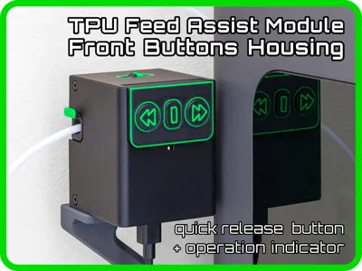
TPU Feed Assist Module Housing front buttons


Print Profile(1)
Bill of Materials


Description
Membership
Do you want to sell 3D prints of this model? With a small expense you can earn big. Join the Membership program and choose the license that best suits your business!
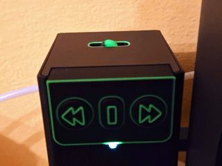
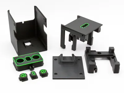
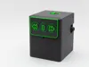
All the accessories I design and print meet my needs, and the TPU Feed Assist Module is no exception: I have the printer on a raised surface, so I prefer to use the module with the buttons on the front rather than on top. The LED has been moved to the front, under the keypad.
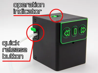
I've also added the operation indicator on the top so I don't have to look at the gears through the slot and I included a quick release button to detach the PTFE filament input tube.
This housing is for the original Bambulab hardware, and the assembly procedure is completely similar. You can refer to the Bambu Lab Wiki: TPU Assist Module Assembly & Usage Guide
Instructions and tips for easy assembly | ||
Place the keypad and printed buttons face down. Insert the buttons, sliding them into the appropriate slots. Make sure they're all aligned, lift the keypad up, and check that they all come out the same way.  | Place the Button switch plates and secure them with the M2.5x8 screws. Make sure to insert the connectors as shown in the photo: green wire for filament feed, yellow wire in the center position, red wire for filament unload.  | Place the housing cover with the flat side facing down and insert the keypad into the appropriate grooves, widening the two vertical parts if necessary. Use the guide circled in red to keep the cables tidy.  |
Insert the small pin into the colored wheel: they aren't designed to be stuck together, they should move and rotate freely. Place this assembly in the appropriate slot as shown in the photo.  | Now place the extruder assembly with the yellow gear facing down and make sure it fits into the various guides of the printed model. It's time to connect the cable with the two black wires to the Hall sensor board.  | Match the bottom frame to the top frame, making sure the two parts fit together at the four vertical uprights. Secure them using two M3x10 screws. Use the part indicated by the arrow to keep the cables tidy.  |
Place the circuit board in the designated space as shown in the photo. Secure it with two M3x10 screws.  | Plug the extruder connector and the keypad connector on the circuit board. Insert the LED into the slot on the button panel.  | Secure the rear panel with the M2.5x8 screws, then place the the quick release button as shown in the photo.  |
Slide the cover making sure the quick-release button fits into the slot. A quick-release button is not needed on the opposite side because the PTFE tube connection is easily accessible.  | Close the cover by securing it with M2.5x8 screws and the assembly is complete. Don't overtighten any screw, they are all self-tapping and will never come loose on their own.  | The TPU feed assist module is ready! Mount it on its bracket (if you have an H2 series printer, use the low-profile one I designed), connect the bottom connector, and you're ready to print.  |
Need a lowered bracket to leave the two filament ports on your printer free? Try this!

License
You shall not share, sub-license, sell, rent, host, transfer, or distribute in any way the digital or 3D printed versions of this object, nor any other derivative work of this object in its digital or physical format (including - but not limited to - remixes of this object, and hosting on other digital platforms). The objects may not be used without permission in any way whatsoever in which you charge money, or collect fees.
Comment & Rating (60)