
Push-to-Open Functional Model – New Concept
Print Profile(2)
Description
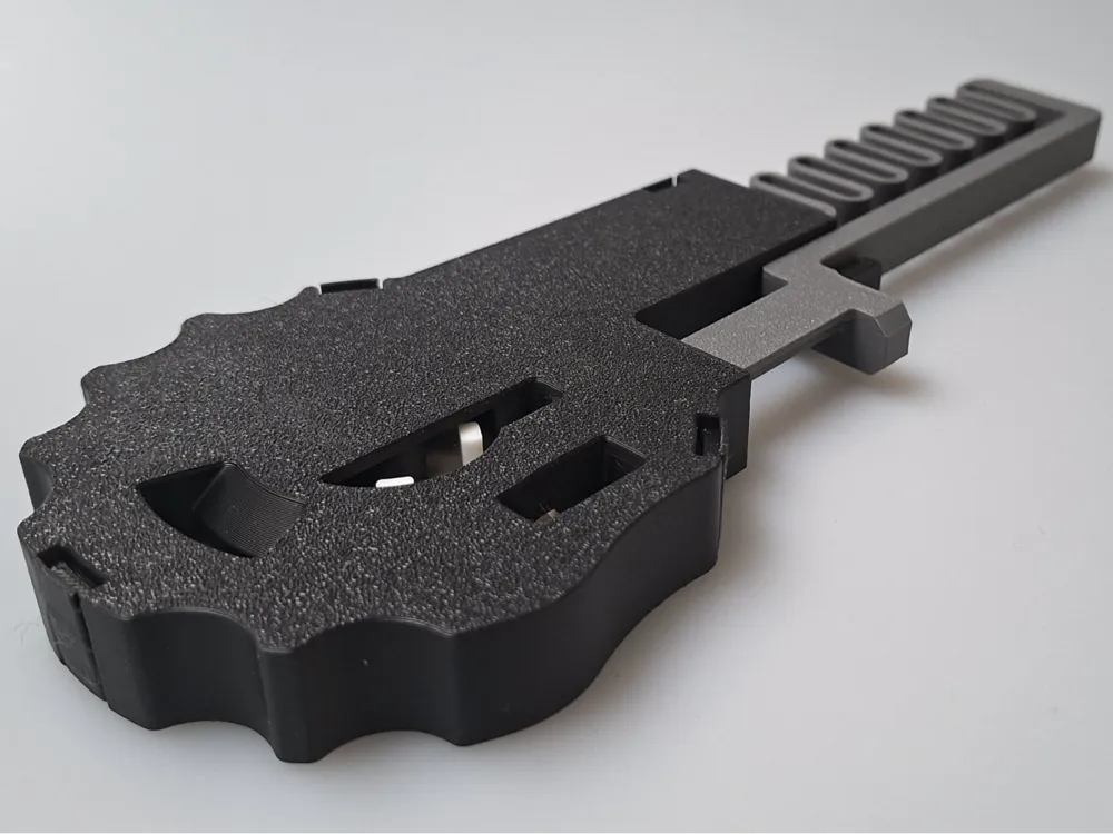

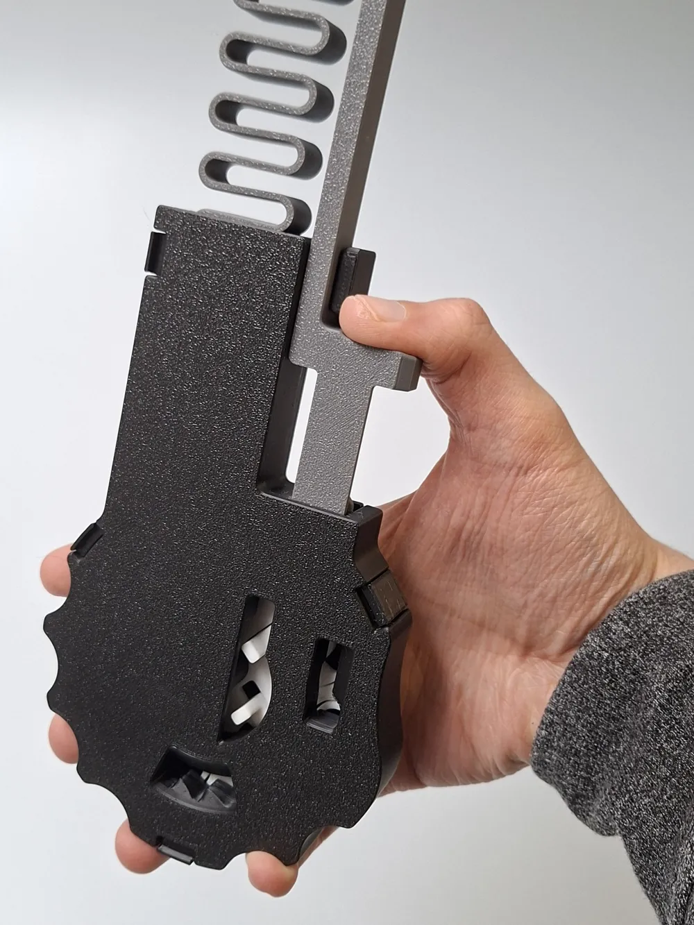
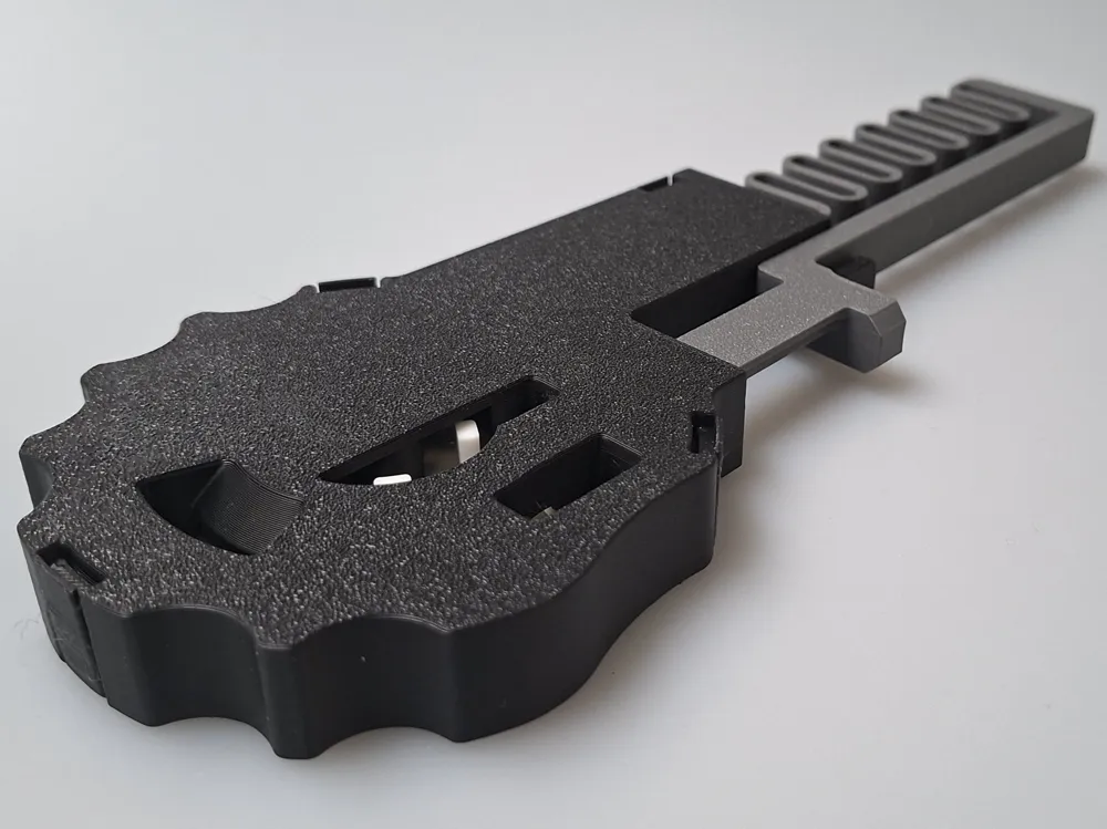
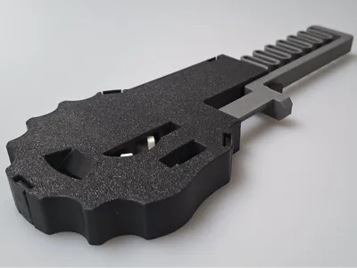
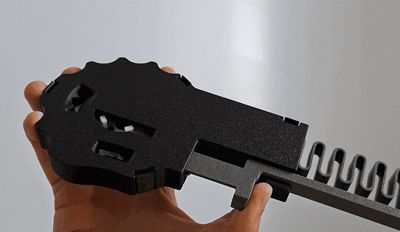
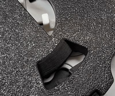
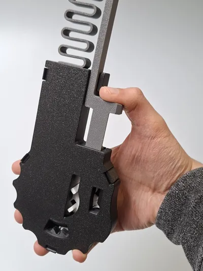
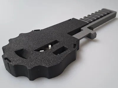
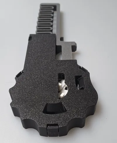
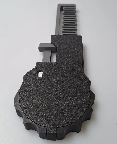
A fully 3D-printable Push-to-Open mechanism with 4 tactile click stages and a completely new rotating locking wheel concept.

- Snap-fit assembly
- No supports required
- No additional hardware
- No tools required
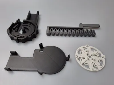
- 4 parts
- 1 printing plate
- Approx. 3 hours print time
- Approx. 110 g filament
Tested with PLA, standard print settings and the printer X1E and X1C
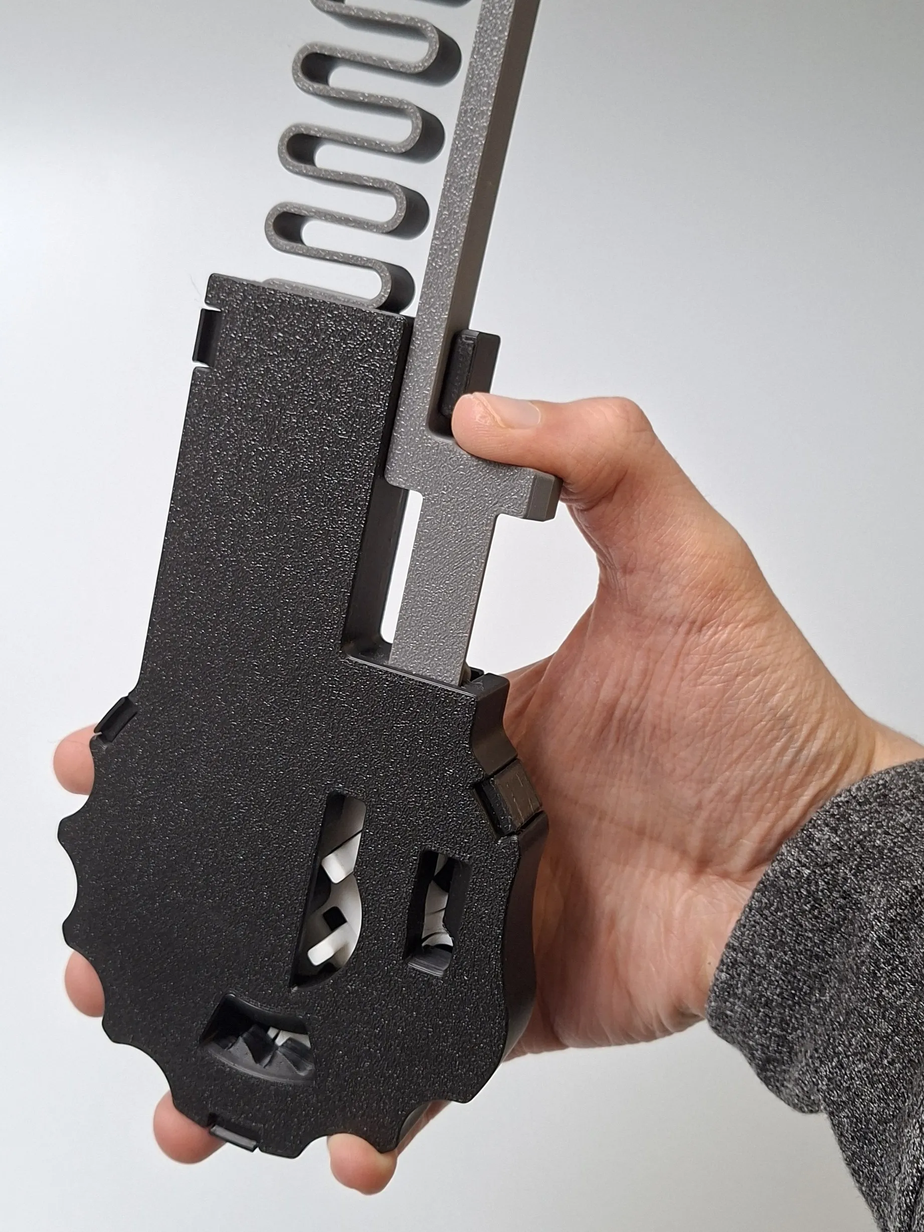
I designed a completely new Push-to-Open (Push-to-Lock / Push-Push) mechanism.
This model is intended as a functional demonstration of the working principle and can be assembled quickly using snap-fit connections. I plan to use this Push-to-Open principle in future projects.


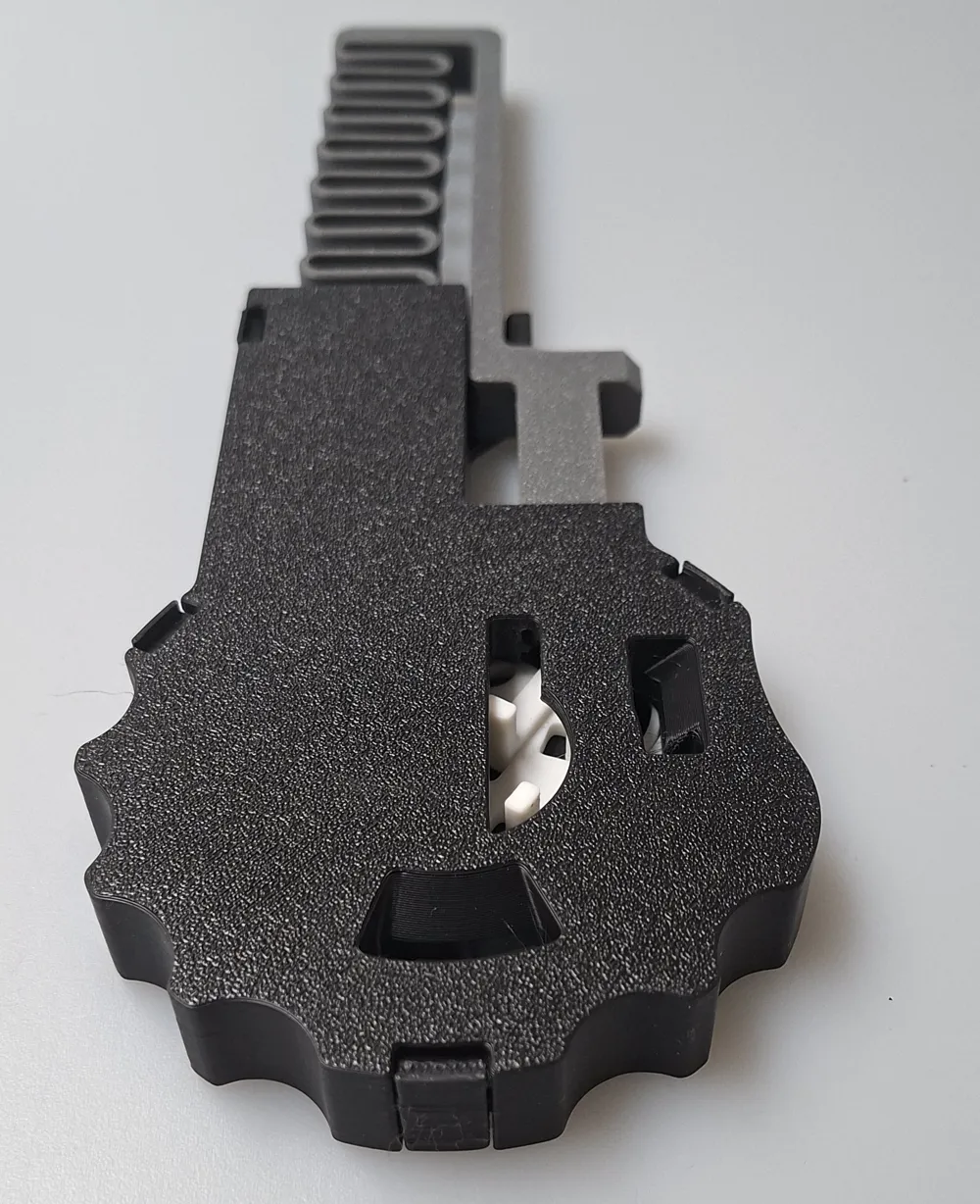
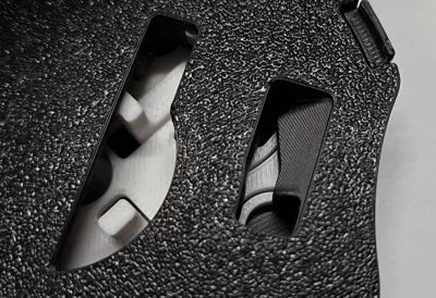
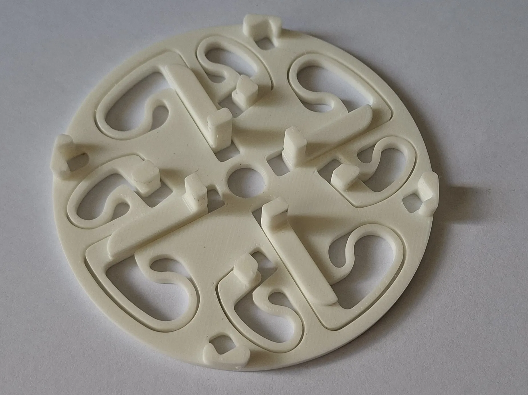
Unlike other 3D-printed Push-to-Open mechanisms, this new concept is based on a wheel with movable print-in-place contact pins. To make the mechanism easier to understand, I added viewing windows to the model so every movement step can be observed clearly.
The mechanism creates 4 distinct click sounds that provide both tactile and audible feedback during every cycle🔔:
- The first click indicates that the button can be released
- The second click confirms that the mechanism is locked
- Pressing again creates the third click, indicating that the button can be released.
- The fourth click confirms that the mechanism is open and the cycle can start again
Additionally, the spring elements inside the mechanism are not permanently loaded in the locked or unlocked position, which increases durability
(This does not apply to the spring that retracts the sliding latch). The locking wheel rotates 90° during each open-close cycle.
Suitable Applications
This functional model is suitable for:
- Educational and demonstration purposes
- Mechanical concept studies
- DIY projects
- Prototype development for Push-to-Open systems
- Just to have fun with the mechanism😉
I believe this mechanism has potential for many different applications and further development. For example:
- Different spring forces for opening and closing could be implemented
- Different actions could be triggered after each 90° rotation
- The mechanism could be activated from all four sides
I am open to application ideas, improvement suggestions, and remixes.👐
Print Settings and Material
The mechanism can be printed without any special print settings.
I tested the mechanism using PLA for all parts. Other materials may require adjustments and were not tested.
In my tests, the spring elements of the locking wheel were stiffer when printed in standard PLA, which made the click sounds more noticeable.
PLA Tough+ for the locking wheel was more flexible and allowed the mechanism to run slightly smoother, but the click sounds were less pronounced.
Assembly
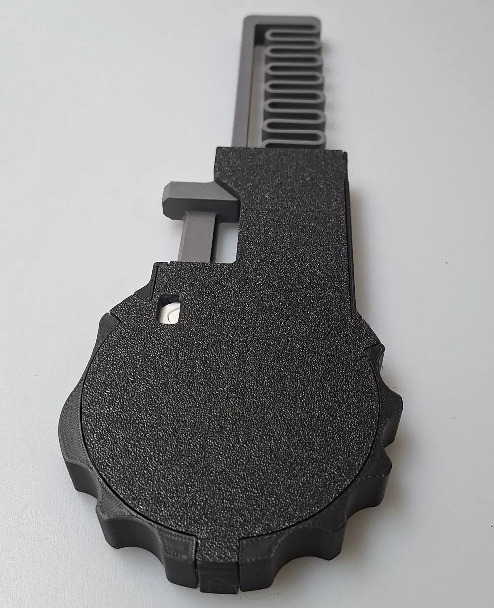
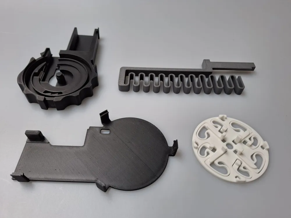
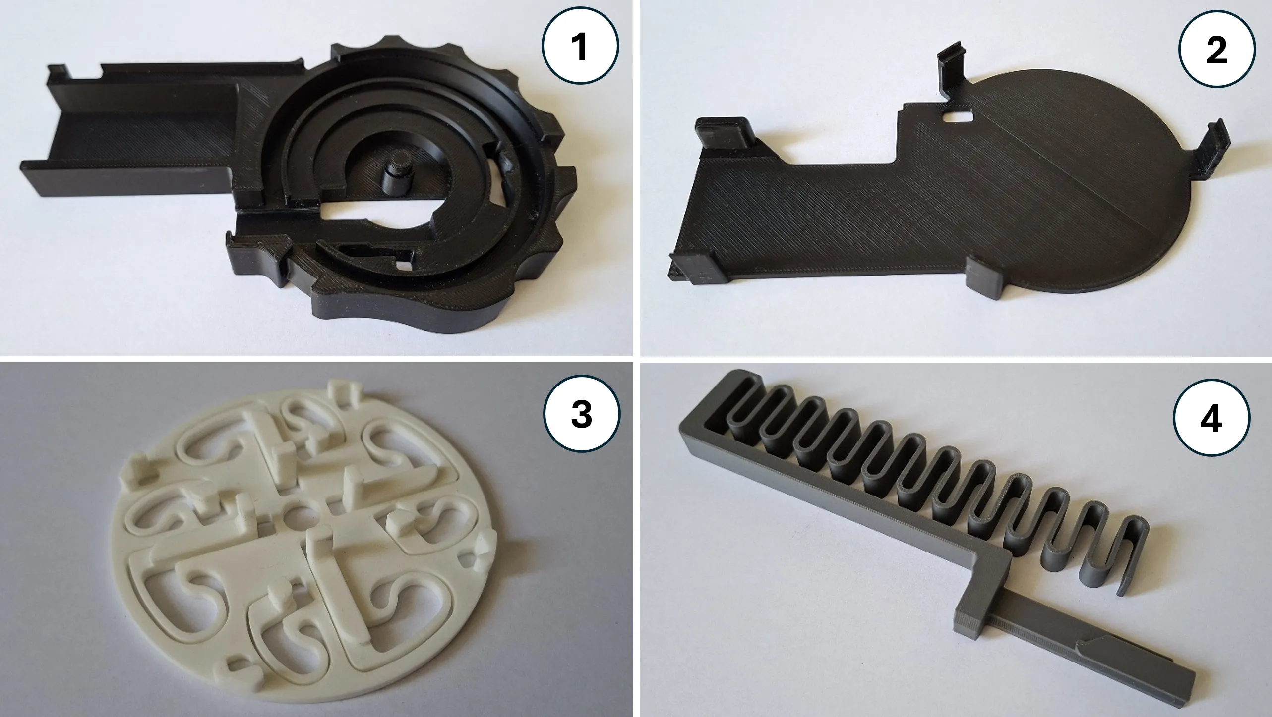
The functional model consists of four parts:
- Housing ①
- Base plate ②
- Locking wheel ③
- Spring-loaded sliding latch ④
Do not heavily load the spring elements immediately after printing. Allow the parts to cool down completely first.
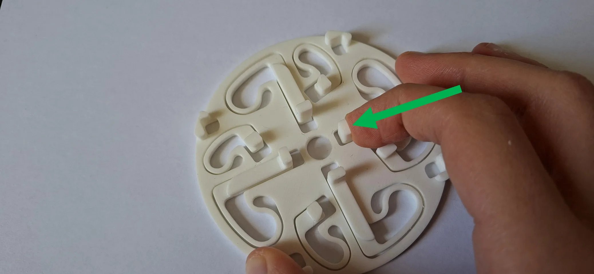
- Check if the spring elements inside the locking wheel can move freely. Sometimes a small amount of plastic may fuse inside the gap during printing. This can usually be separated easily. Press each pin toward the center as shown in the image.
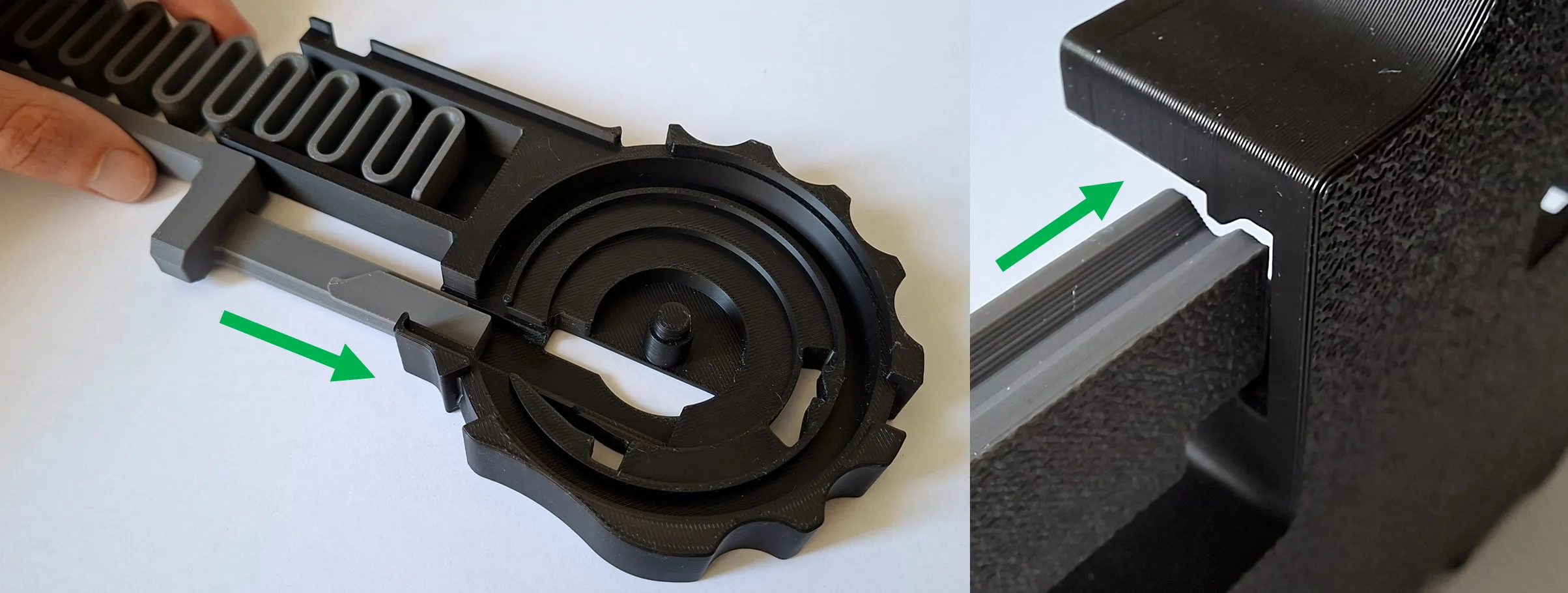
2. Insert the spring-loaded sliding latch into the housing as shown in the image. Make sure the guide rails are aligned correctly.
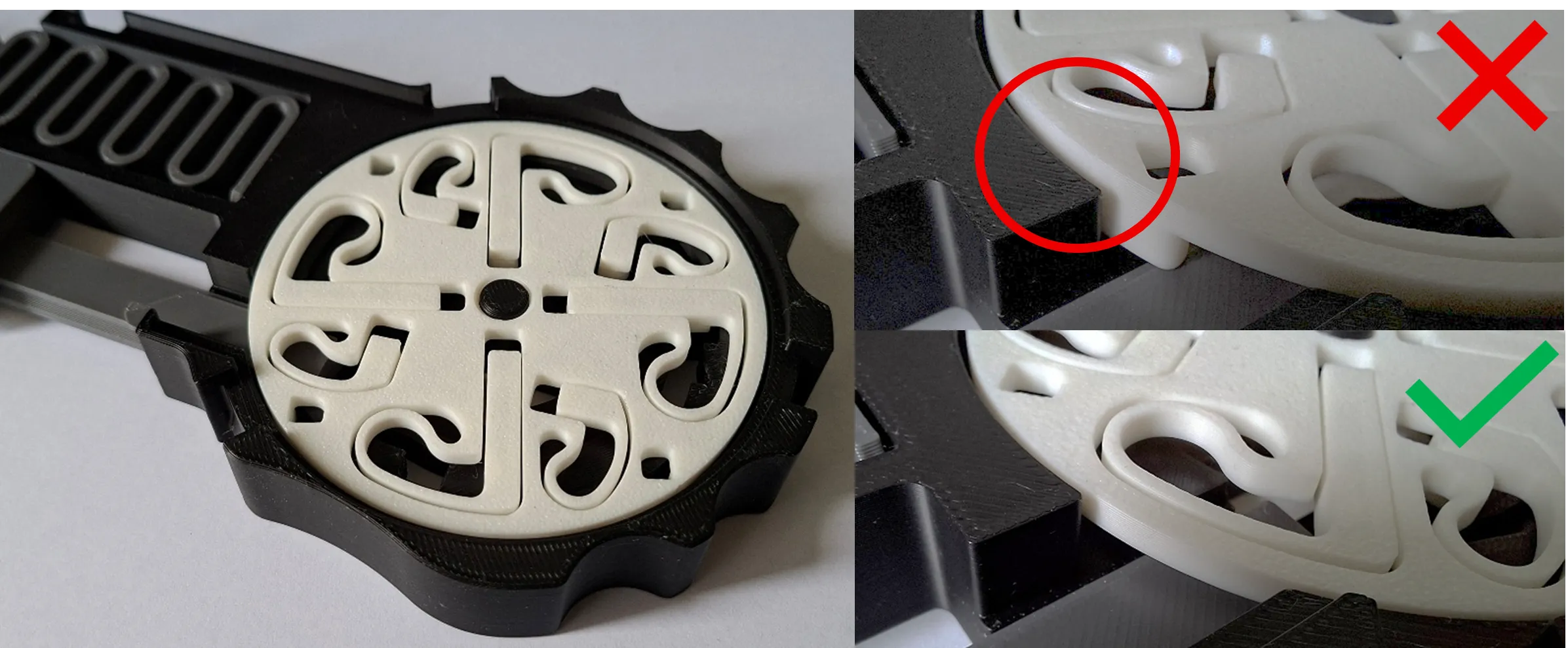
3. Place the locking wheel into the housing. The locking wheel must sit flush inside the housing as shown in the image.
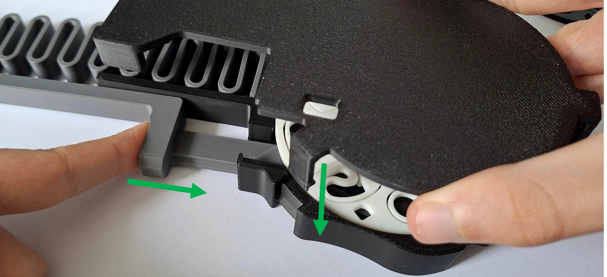
4. Slightly press down the spring-loaded sliding latch at the push point while inserting the base plate from the top until the snap-fits lock into place.
5. Finished!🥳
Do not store the spring of the sliding latch in a permanently preloaded position, as this may reduce the spring force over time.
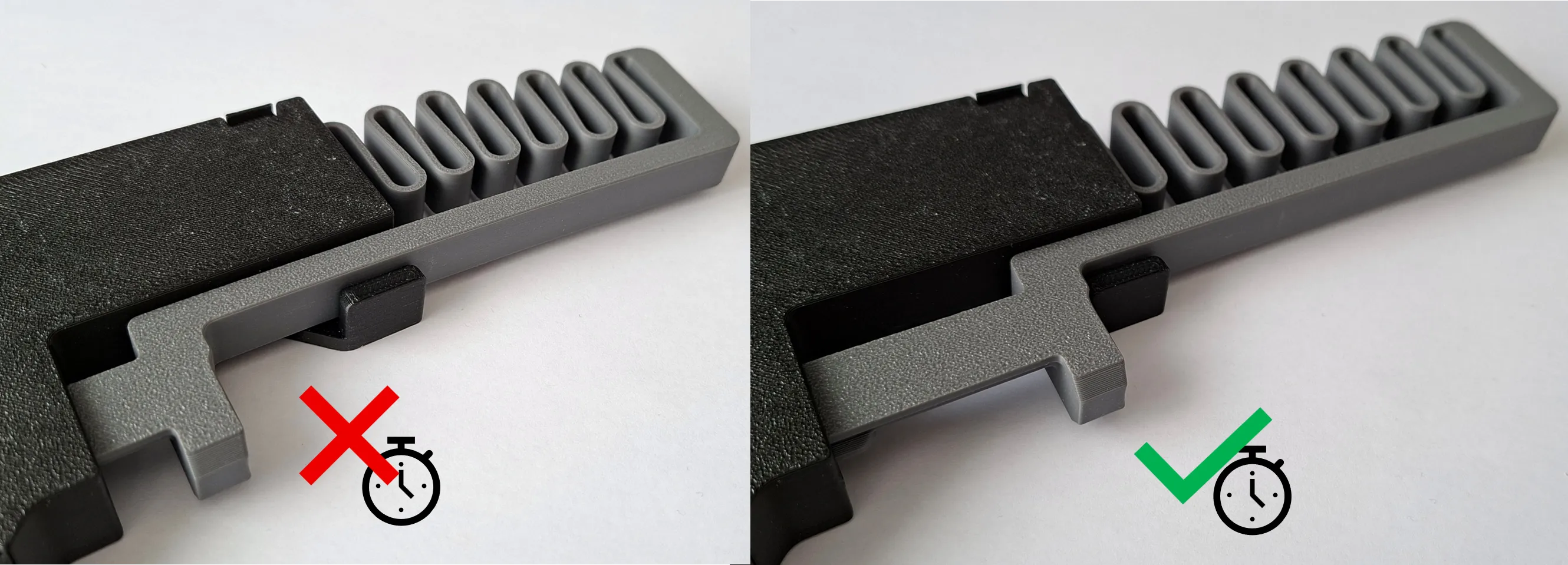
From my experience, the mechanism runs smoother after several cycles.
It is important that the locking wheel can rotate freely. Too much friction may cause the mechanism to malfunction. This was a problem in my first prototypes, but the newer versions worked reliably.
If you experience any issues, feel free to leave feedback.🤔
Detailed Function Description (Now things start getting a bit more technical😉)
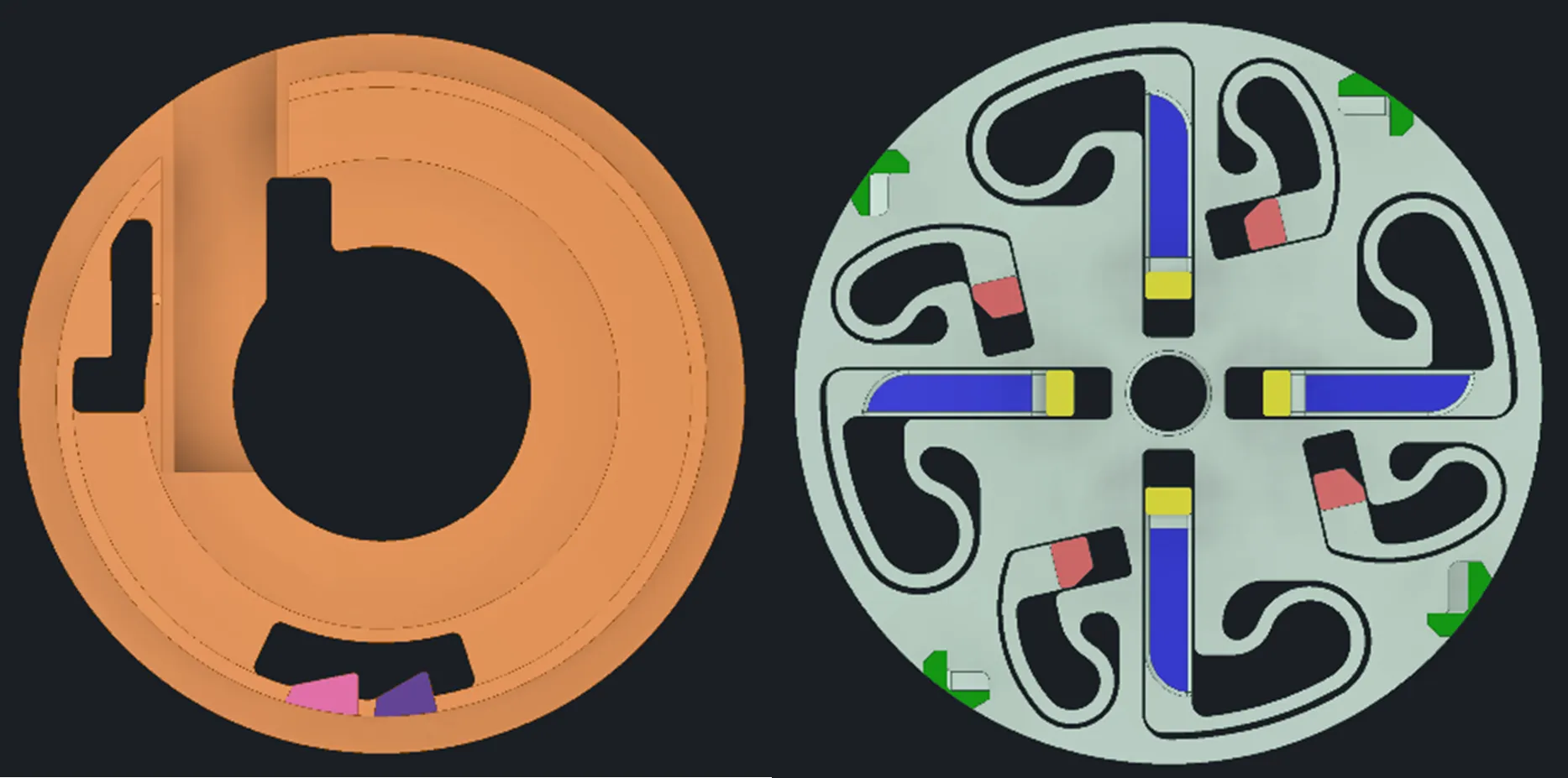
I marked the most important elements with colors:
The housing contains:
- First locking position (pink)
- Second locking position (purple)
The locking wheel contains:
- First contact pin (red)
- Second contact pin (yellow)
These pins can move toward the center and spring back afterward.
The locking wheel also contains:
- Spring-loaded locking sliders (blue)
- Rotation stops (green)
The following section explains the closing and opening sequence of the mechanism.
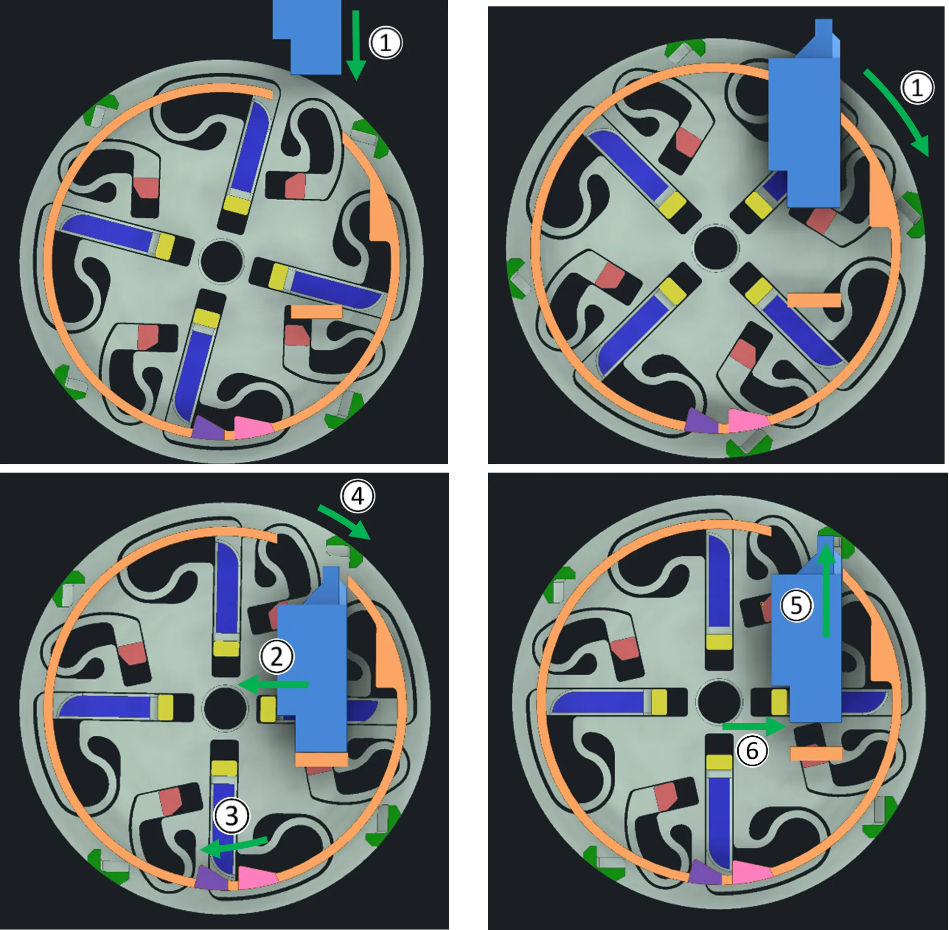
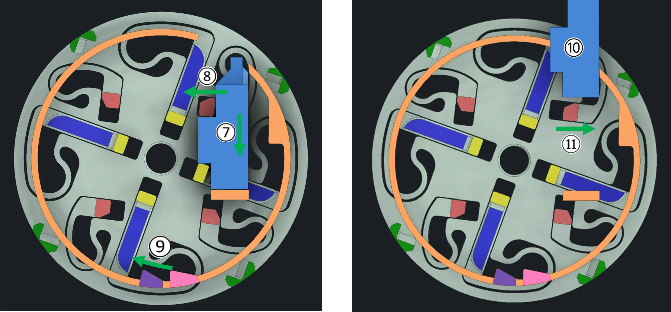
The circled numbers correspond to the images shown below.
Closing Process
During closing, the spring-loaded sliding latch is inserted from the top by hand and presses against the first contact pin, causing the locking wheel to rotate clockwise ①.
At the same time, the second contact pin is pushed toward the center by the side wall of the sliding latch and becomes preloaded, creating enough space for the sliding latch to move to the end position②.
As soon as the sliding latch reaches the end position, the locking slider snaps into the first locking position ③. This prevents the locking wheel from rotating backward.
The spring-loaded sliding latch can now move backward slightly using the spring force (spring not shown). Due to the previous rotation of the locking wheel, the return path of the sliding latch is blocked by the rotation stop ④.
Because of this, the sliding latch can only move back to the rotation stop position and the mechanism is now locked ⑤.
In this position, the preloaded second contact pin can move back into the matching recess of the sliding latch ⑥.
Once this happens, the Push-to-Open mechanism can be opened again.
Opening Process
Opening is performed by pressing the sliding latch a second time by hand.
The sliding latch pushes the second contact pin downward until the end stop is reached ⑦. The required travel distance is only 5 mm.
During this movement, the first contact pin is preloaded against the side wall of the sliding latch ⑧.
When the sliding latch reaches the end position, the locking slider snaps into the second locking position to again prevent the locking wheel from rotating backward ⑨.
The sliding latch can now be fully pulled out of the mechanism by the spring force (spring not shown) ⑩.
Since the first contact pin is no longer pressed against the side wall of the sliding latch, it can spring back into its original position ⑪.
The system is now back in its starting position and the cycle can begin again.
Thanks for checking out the project! 😁
License

You may create derivative works based on this object, provided that all such derivative works are published exclusively on the MakerWorld platform and include proper attribution to the original creator. You may not share, upload, host, distribute, or publish this object—or any derivative work of this object—on any other digital platform, marketplace, or distribution channel. Commercial use of this object and any derivative works is strictly prohibited. This includes, but is not limited to, selling, renting, sublicensing, or using the object in any context in which you receive monetary compensation or other financial benefits.


Comment & Rating (16)