Back to the Future Transformers Skilz Skateboard Transforming Figure Compatible with Gigawatt Toy Scale


Print Profile(1)
Bill of Materials

Description
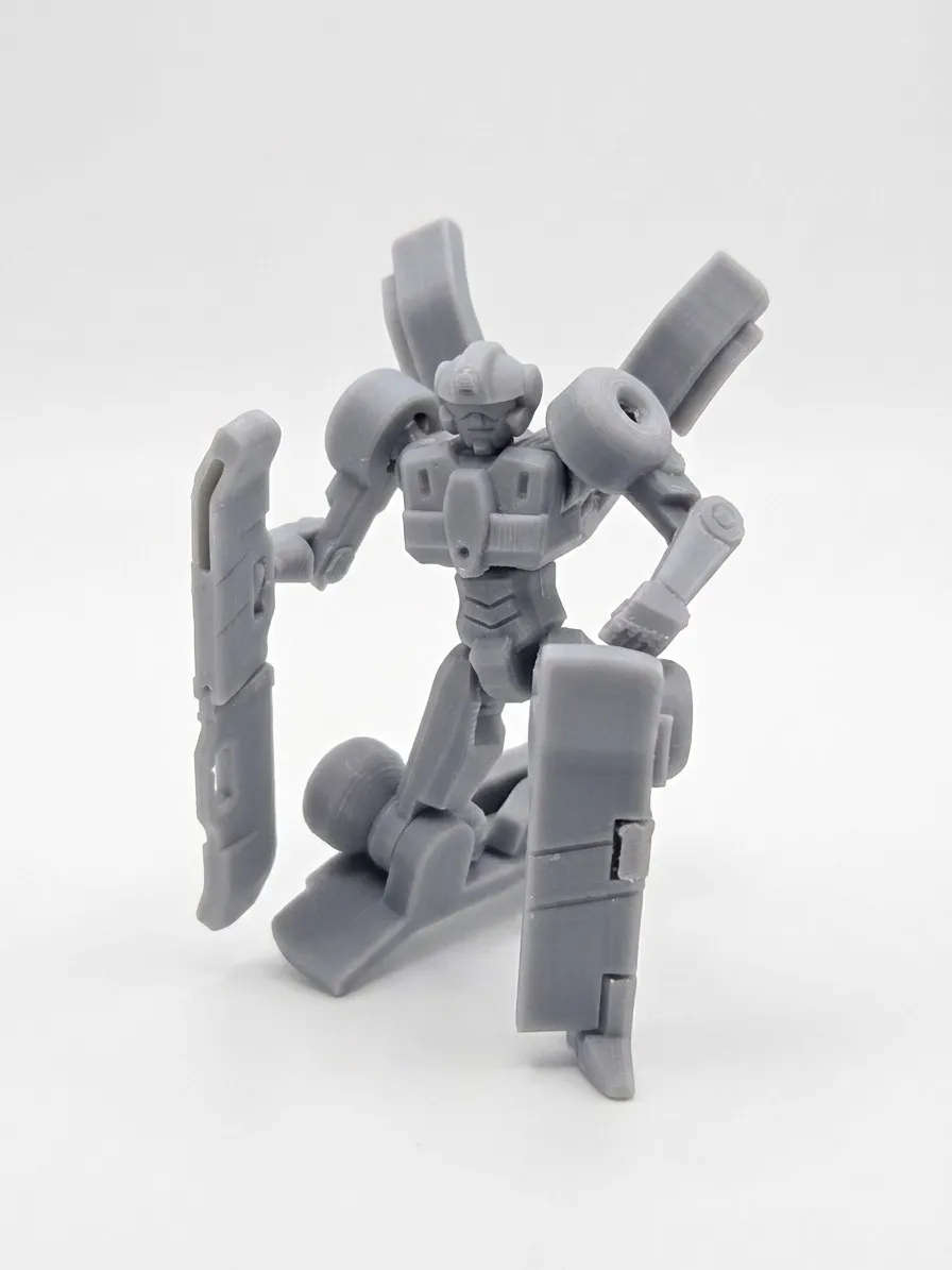
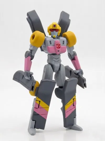
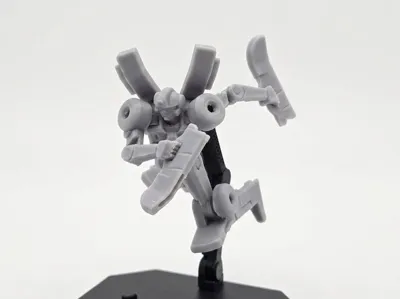
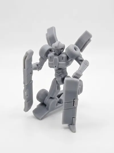
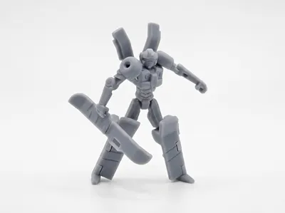
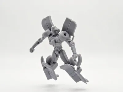
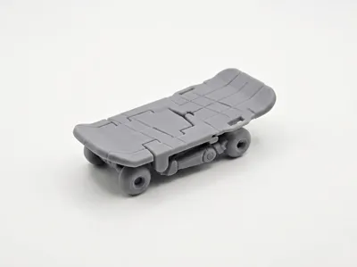
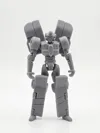
Hello everyone! This model is of the Transformer Skilz, who can transform into a skateboard, from the IDW "Transformers / Back to the Future" crossover comic. Since no official physical toy that matches the scale of the DeLorean Gigawatt has been released, I tried to model and design one myself. As this is just an amateur work of personal design, it may not be as perfect as an official toy, but the basic transformation function and articulated joints have been implemented. I'm sharing it with friends who also like this character!

The model is designed for single-color printing, with subsequent painting, because the parts are small, and multi-color printing with AMS might not yield optimal results
Basic Model Design:
- [Attempt at Full Transformation]: The design allows transformation from robot mode to skateboard mode without disassembling parts, but some parts can also be removed to serve as original weapons, making the overall proportions more harmonious
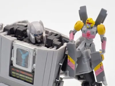
- [Matches Gigawatt Scale]: The robot mode's dimensions have been specifically adjusted to match the official DeLorean Gigawatt, resulting in a suitable sense of proportion when placed together
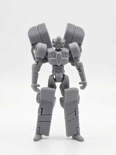
- [Articulated Joints and Stand]: The model features basic articulated joints for pose adjustment, and a 3mm diameter socket is included on the back for installing universal stands, allowing for various display options
⚠️ Some Printing and Assembly Tips:
- [0.2 Nozzle and 0.4 Nozzle]: Using a 0.2 nozzle with a 0.06 layer height can achieve optimal print quality. If using a 0.4 nozzle, a 0.08 layer height is required, but parts may have small defects requiring additional trimming
- [Filament and Build Plate Cleaning]: It is recommended to use dried PLA filament for printing. Properly clean the build plate before printing to ensure parts do not shift during the process
- [Print in Batches]: Due to the numerous small parts, they are arranged in frames for printing. It is recommended to print in batches according to the file's arrangement to ensure a higher success rate and quality
- [Details and Tolerances]: Parts are small, and after printing, joint areas or pinholes may require trimming or fine-tuning with a hobby knife for smoother assembly and transformation
- [Supports and Build Plate Contact Surface]: When removing supports, ensure complete removal, as residual support can affect assembly, leading to overly tight or even damaged parts. Pay attention to any burrs on the parts' contact surfaces with the build plate, as these can also affect assembly
- [Overhang Trimming]: Some overhangs may not require supports, but drooping filament needs to be handled to avoid affecting assembly
After each frame is printed and cooled, it can be lifted directly from here to separate the parts from the build plate in one go

Here are the detailed assembly steps:
1. Insert the body part sideways at a 90-degree angle, then rotate it upright. If it's too tight, there might be burrs on the ball joint that need slight trimming

2. The thigh parts can be pressed directly into place. Applying pressure on a tabletop will make it easier. Note that the left and right parts are different

3. The lower legs are installed symmetrically for both left and right. The part slots can be test-fitted first for tightness before attaching the C-clip

4. The shoulder joint can be pressed in from approximately a 45-degree angle. Be careful of the shoulder joint sliding when installing the upper arm. Placing the upper arm part on a tabletop before pressing it in will make it easier to apply force

5. The arm C-clip is relatively fragile; check the part's condition for any necessary trimming before installation

6. Insert the head sideways at a 90-degree angle, then rotate it upright

7. If the rear socket part lacks support, there may be some hanging filament that needs to be removed. There is support on the small wing's pivot that needs to be removed; ensure it is completely clean, otherwise, it may damage the rear slot. When installing, it is recommended to snap it in from the side before rotating. During the first rotation, be careful not to let the pivot slide out of the slot

8. For the first transformation of the feet, due to the small size of the parts, care must be taken when pulling them out of the slots. Rotating the foot parts can prevent interference during storage. Once complete, there are snaps between the foot parts and the lower legs for securement

This is an attempt still in the experimental and optimization phase, not a very mature model. If you have any suggestions for modifications, please feel free to leave comments below for discussion, thank you everyone!
License
You shall not share, sub-license, sell, rent, host, transfer, or distribute in any way the digital or 3D printed versions of this object, nor any other derivative work of this object in its digital or physical format (including - but not limited to - remixes of this object, and hosting on other digital platforms). The objects may not be used without permission in any way whatsoever in which you charge money, or collect fees.
Comment & Rating (38)